EP1850896B1 - Aerosolerzeugungsvorrichtung und inhalationstherapiegerät mit einer derartigen vorrichtung - Google Patents
Aerosolerzeugungsvorrichtung und inhalationstherapiegerät mit einer derartigen vorrichtung Download PDFInfo
- Publication number
- EP1850896B1 EP1850896B1 EP06702976.9A EP06702976A EP1850896B1 EP 1850896 B1 EP1850896 B1 EP 1850896B1 EP 06702976 A EP06702976 A EP 06702976A EP 1850896 B1 EP1850896 B1 EP 1850896B1
- Authority
- EP
- European Patent Office
- Prior art keywords
- aerosol generating
- generating device
- flexible substrate
- membrane
- actuating device
- Prior art date
- Legal status (The legal status is an assumption and is not a legal conclusion. Google has not performed a legal analysis and makes no representation as to the accuracy of the status listed.)
- Expired - Lifetime
Links
Images



Classifications
-
- B—PERFORMING OPERATIONS; TRANSPORTING
- B05—SPRAYING OR ATOMISING IN GENERAL; APPLYING FLUENT MATERIALS TO SURFACES, IN GENERAL
- B05B—SPRAYING APPARATUS; ATOMISING APPARATUS; NOZZLES
- B05B17/00—Apparatus for spraying or atomising liquids or other fluent materials, not covered by the preceding groups
- B05B17/04—Apparatus for spraying or atomising liquids or other fluent materials, not covered by the preceding groups operating with special methods
- B05B17/06—Apparatus for spraying or atomising liquids or other fluent materials, not covered by the preceding groups operating with special methods using ultrasonic or other kinds of vibrations
- B05B17/0607—Apparatus for spraying or atomising liquids or other fluent materials, not covered by the preceding groups operating with special methods using ultrasonic or other kinds of vibrations generated by electrical means, e.g. piezoelectric transducers
- B05B17/0638—Apparatus for spraying or atomising liquids or other fluent materials, not covered by the preceding groups operating with special methods using ultrasonic or other kinds of vibrations generated by electrical means, e.g. piezoelectric transducers spray being produced by discharging the liquid or other fluent material through a plate comprising a plurality of orifices
- B05B17/0646—Vibrating plates, i.e. plates being directly subjected to the vibrations, e.g. having a piezoelectric transducer attached thereto
-
- A—HUMAN NECESSITIES
- A61—MEDICAL OR VETERINARY SCIENCE; HYGIENE
- A61M—DEVICES FOR INTRODUCING MEDIA INTO, OR ONTO, THE BODY; DEVICES FOR TRANSDUCING BODY MEDIA OR FOR TAKING MEDIA FROM THE BODY; DEVICES FOR PRODUCING OR ENDING SLEEP OR STUPOR
- A61M11/00—Sprayers or atomisers specially adapted for therapeutic purposes
- A61M11/005—Sprayers or atomisers specially adapted for therapeutic purposes using ultrasonics
-
- A—HUMAN NECESSITIES
- A61—MEDICAL OR VETERINARY SCIENCE; HYGIENE
- A61M—DEVICES FOR INTRODUCING MEDIA INTO, OR ONTO, THE BODY; DEVICES FOR TRANSDUCING BODY MEDIA OR FOR TAKING MEDIA FROM THE BODY; DEVICES FOR PRODUCING OR ENDING SLEEP OR STUPOR
- A61M15/00—Inhalators
- A61M15/0085—Inhalators using ultrasonics
Definitions
- the present invention relates to an aerosol generating apparatus and an inhalation therapy apparatus in which the aerosol generating apparatus is provided.
- a medicament-containing liquid in the form of a respirable aerosol is provided to a patient for inhalation, which is generated by a suitable aerosol generator in the inhalation therapy device.
- a therapeutically high-quality aerosol is generated from the smallest liquid droplets with the aid of a membrane which is set into oscillation by an actuating device, for example a piezo ring.
- an actuating device for example a piezo ring.
- a vibration suspension of an aerosol generator is known from WO 2004/014569 , are also provided in the web-like suspensions, but not only extend radially, but also have a tangential component, but remain in the plane of the aerosol generator.
- a space-saving oscillatory arrangement is created, which makes it possible to hang the aerosol generator actually swingable. But even this proposal is limited to the suspension of the aerosol generator.
- US 2003/218077 A1 shows an atomizer with a device with a piezoelectric actuator and an atomizer plate. This device is supported by wire-like support elements above and below the atomizer.
- the upper and lower wire-like support members are resilient and press against the underside and top of the actuator, respectively, to hold it in place.
- electric wires are connected to the wire-like support members, whereby they become electrically conductive.
- US Pat. No. 4,605,167 A1 shows a liquid ejection device in which a bimorph vibration system is formed with a nozzle, and this is snapped into an elastic body, which is typically made of rubber.
- This elastic body may be designed for attachment in an aerosol generating device, and a Provide continuity for a single electrical line.
- the object of the present invention is therefore to provide an aerosol generating device in which a vibration-favorable suspension is realized, but at the same time covers other aspects of the structural design of the aerosol generator.
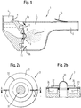
- FIG. 1 To clarify the field of application of an aerosol generating device described in more detail below is introduced by way of FIG. 1 the structure of an exemplary inhalation therapy device explained that with an aerosol generating device according to the invention is equipped.
- the inhalation therapy device 1 shown by way of example comprises, in addition to an aerosol generating device 3 according to the invention, a reservoir 4 for a medicament-containing liquid 5 which is supplied to the aerosol generating device 3 and a misting chamber 6 into which the aerosol generating device 3 emits the aerosol 7 generated from the liquid when the aerosol generating device 3 is vibrated.
- a patient inhales the aerosol 7 via a mouthpiece 8, with additional breathing air flowing through inhalation valves 9a and 9b into the atomizing chamber 6.
- the inhalation valves 9a and 9b close and the exhaled air escapes through an exhalation valve 10, which is located, for example, on the mouthpiece 8 of the inhalation therapy device 1.
- FIG. 1 shows, the aerosol generating device 3 is disposed in the inhalation therapy device 1 and for this purpose according to the invention attached to a mounting portion 11 of the inhalation therapy device 1, for which the aerosol generating device according to the invention comprises a flexible substrate 31, which hereinafter with reference to FIG. 2 will be explained in more detail.
- FIG. 2a a plan view of a rotationally symmetrical ausgestaltetes embodiment of an inventive aerosol generating device
- FIG. 2b a sectional view taken along the line AA in FIG. 2a shows.
- the aerosol generating device 3 comprises a flexible substrate 31, an actuating device 32 which can be activated by electrical signals and a diaphragm which can be set in vibration by the actuating device 33, and electrical leads 34 for the supply of electrical signals to the actuator.
- the flexible substrate 31 is firstly configured for attachment of the aerosol generating device 3 to a mounting area of an inhalation therapy device, secondly supports the actuator 32 and the diaphragm 33, and thirdly carries the electrical leads 34.
- the flexible substrate 31 thus functions as a support for electrical addition Lines according to the invention on the one hand the purpose of attaching the aerosol generating device according to the invention in an inhalation therapy device, and on the other hand the purpose of holding the actuator 32 and the membrane 33, which together form a structure to be vibrated for the generation of aerosol, to support vibration favorable. Because of the flexibility of the substrate 31, the oscillations carried out by the oscillatory structure are not impaired or impaired only to a negligible extent, but at the same time a secure positioning of the oscillatory structure is achieved. Thus, the invention advantageously exploits the flexibility of the line substrate by being used for the positioning of the aerosol generator in a therapy device and for the vibration decoupling of the oscillating structure.
- Flexible boards or flexible printed circuit boards / foils for example polyimide (PI), polyethylene naphthalate (PEN), polyester (PET) or another suitable insulating material, for example with typical thicknesses of the order of 10, are particularly suitable as a flexible substrate 31 up to 250 .mu.m, are applied to the conductors, for example made of Cu, Ag, Al or another conductive material or are integrated in such a conductor.
- the structure of these boards or Printed circuit boards or films may be one or more layers and may have a cover layer.
- the design of the flexible substrate 31 for attachment of the aerosol generating device in an inhalation therapy device for example by the dimensions of the flexible substrate 31 are adapted to the geometry of the mounting portion 11 and a fixation, for example by gluing, as in FIG. 2b shown, or by clamping, snapping, plugging or otherwise possible.
- actuator 32 is advantageously a component of piezoelectric or other material that responds to the supplied electrical signals and then ensures that the membrane 33 is set in vibration.
- the membrane 33 is preferably made of a metal and has a plurality of holes in a region formed for aerosol generation.
- the membrane 33 is preferably arched in the relevant area for the aerosol generation, as exemplified in FIG. 2b is shown.
- FIG. 2 shown embodiment of an inventive aerosol generating device
- the actuator 32 between the flexible substrate 31 and the membrane 33 is arranged.
- FIG. 3 shows embodiments of inventive aerosol generating devices, which are modified with respect to this arrangement. So shows FIG. 3a an embodiment in which the membrane 33 is disposed between the flexible substrate 31 and the actuator 32, while Figure 3b and Figure 3c Embodiments show in which the flexible substrate 31 between the actuator 32 and the Membrane 33 is arranged. From the inhalation therapy device is in the presentation of the FIG. 3 only the attachment area 11 required for the description of the invention has been shown, while other details have been omitted to simplify the illustration.
- the vibrations required for aerosol generation are caused by the actuator 32 in interaction with the membrane 33 and / or the flexible substrate 31.
- the actuator 32 is connected to the membrane 33 and / or the flexible substrate 31, for example glued or soldered.
- the design of the structural details of the flexible substrate 31, the actuator 32 and the membrane 33 and the compounds, the vibration characteristics of the oscillatory structure can be influenced to a large extent and define a wide range.
- the electrical lines 34 can also be included.
- the design options are limited to the effect that the flexible substrate 31 is designed according to the invention for the vibration-favorable fixation of the aerosol generator and thus usually as well as the membrane 33 is very thin, in terms of the production of well-defined holes in practice no very having large thickness.
- the design options are limited to the effect that the flexible substrate 31 is designed according to the invention for the vibration-favorable fixation of the aerosol generator and thus usually as well as the membrane 33 is very thin, in terms of the production of well-defined holes in practice no very having large thickness.
- the design options are limited to the effect that the flexible substrate 31 is designed according to the invention for the vibration-favorable fixation of the aerosol generator and thus usually as well as the membrane 33 is very thin, in terms of the production of well-defined holes in practice no very having large thickness.
- a further substrate 35 is provided, which preferably consists of a metal and the extent matched to the actuator 32 and connected to it, that when activated the actuating device 32 are caused by supplied electrical signals bending vibrations, ie vibrations out of a plane which is spanned by the flexible substrate 31, the actuator 32, the membrane 33 and the further substrate 35.
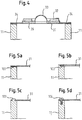
- FIG. 5 various ways of attaching the flexible substrate to the mounting area of an inhalation therapy device are shown.
- FIG. 5a the above-mentioned adhesive bond between the flexible substrate 31 and the mounting portion 11 is shown again.
- the surface 101 of the attachment region 11 forms either completely or at least partially the contact surface for the bond.
- FIG. 5b a configuration is shown in which a groove 102 is provided on the mounting portion 11, in which an edge, preferably the peripheral edge, of the flexible substrate 31 is inserted. Due to the flexibility of the substrate 31, it is possible, even with a circumferential groove 102, to insert the flexible substrate 31, since it typically has sufficient strength can be deformed to be plugged in, and then returns to its original shape.
- FIG. 5a the above-mentioned adhesive bond between the flexible substrate 31 and the mounting portion 11 is shown again.
- the surface 101 of the attachment region 11 forms either completely or at least partially the contact surface for the bond.
- FIG. 5b a configuration is shown in which a groove 102 is provided on the mounting portion 11,
- FIG. 5c an embodiment is shown in which at the edge of the flexible substrate 31 openings are provided by those in FIG. 5c one is shown.
- the openings pin 103 are engaged, which due to a in the FIG. 5c shown return the flexible substrate 31 fix.
- the tips of the pins 103 are preferably frusto-conical, as in FIG FIG. 5c shown to facilitate insertion into the openings of the substrate 31.
- FIG. 5d an embodiment is shown in which the openings provided in the flexible substrate 31 are used to fix by means of a screw 104 or similar other connector, the flexible substrate 31 to the mounting portion 11.
- the attachment of the aerosol generating device 3 according to the invention in an inhalation therapy device does not have to take place along the entire circumference of the flexible substrate 31.
- the attachment can be achieved at only a few, for example, three locations of the flexible substrate 31 by means of a correspondingly designed attachment region of the inhalation therapy device, which comprises three partial regions 11a, 11b and 11c.
- This design also offers further advantageous design options with regard to a vibration-favorable fixation, which can be used depending on the application. For example, fewer / more or larger / smaller attachment areas may be provided.
- FIG. 1 the attachment of the aerosol generating device 3 according to the invention in an inhalation therapy device does not have to take place along the entire circumference of the flexible substrate 31.
- the attachment can be achieved at only a few, for example, three locations of the flexible substrate 31 by means of a correspondingly designed attachment region of the inhalation therapy device, which comprises three partial regions 11a, 11b and 11c.
- This design also offers further advantageous design
- FIG. 5b shown variant Nevertheless, it is obvious that other mounting options, such as the variants of FIGS. 5a, 5c or 5d can be used.
- FIG. 7 In a region-only attachment to the periphery of the flexible substrate 31, as in FIG. 7 As shown, portions of the substrate located between the fixing portions are also recessed so that tab-like projections 31a, 31b and 31c are formed on the periphery of the substrate. to FIG. 7 It should be noted that here is the variant of FIG. 5d is shown in section-wise embodiment; but also other mounting options, such as the variants of Figures 5a, 5b and 5c can be used.
- the lines 34 carried by the flexible substrate 31 serve primarily for the supply of electrical signals to the actuating device 32.
- the lines or printed conductors are shown only schematically in order to explain in principle that these lines are arranged on or in the flexible substrate 31 are. In the following some advantageous embodiments of the conduit arrangement with reference to the FIGS. 8 and 9 described.
- FIG. 8 shows an exploded view of an aerosol generating device 3, wherein in this arrangement, the flexible substrate 31 is provided with a number of lines 34, 34 a and 34 b, which are applied to the flexible substrate 31. Emphasize is an annular track 34a, which advantageously serves for contacting the actuator 32, wherein in the in FIG. 8 shown embodiment, the contacting is not directly but via the membrane 33.
- the concrete realization of the electrical contacting of the actuating device 32 is not a problem for the skilled person even in the above-mentioned alternative arrangements of flexible substrate, actuator, membrane and possibly further substrate, so that a description of the various Contacting alternatives is dispensable and on the Figures 2 and 3 can be referenced.
- the membrane 33 is made in one piece with the further substrate 35.
- the actuator 32 is according to FIG. 8 arranged on the upper side in the drawing of the further substrate 35 combined with the membrane.
- Alternative designs for this aspect are readily derivable and result for example from the Figures 2 . 3 and 4 ,
- FIG. 8 On the flexible substrate 31 next to the lines 34 and the annular contact surface 34 a further contact surfaces 34 b are shown. Such contact surfaces are used to connect additional electrical components, as exemplified in FIG. 9 are shown.
- a passive component 36 and an active component 37 are provided by way of example in order to make it clear that the use of lines 34 and contact surfaces 34b makes it possible to advantageously exploit the board properties of the flexible substrate 31.
Landscapes
- Health & Medical Sciences (AREA)
- Engineering & Computer Science (AREA)
- Anesthesiology (AREA)
- Biomedical Technology (AREA)
- Heart & Thoracic Surgery (AREA)
- Hematology (AREA)
- Life Sciences & Earth Sciences (AREA)
- Animal Behavior & Ethology (AREA)
- General Health & Medical Sciences (AREA)
- Public Health (AREA)
- Veterinary Medicine (AREA)
- Bioinformatics & Cheminformatics (AREA)
- Pulmonology (AREA)
- Special Spraying Apparatus (AREA)
Description
- Die vorliegende Erfindung betrifft eine Aerosolerzeugungsvorrichtung und ein Inhalationstherapiegerät, in der die Aerosolerzeugungsvorrichtung vorgesehen ist.
- In einem Inhalationstherapiegerät wird eine medikamenthaltige Flüssigkeit in Form eines lungengängigen Aerosols einem Patienten zur Inhalation zur Verfügung gestellt, das von einem geeigneten Aerosolerzeuger in dem Inhalationstherapiegerät erzeugt wird.
- Bei Membran-Aerosolerzeugern wird mit Hilfe einer Membran, die von einer Betätigungseinrichtung, beispielweise einem Piezoring in Schwingungen versetzt wird, ein therapeutisch hochwertiges Aerosol aus kleinsten Flüssigkeitströpfchen erzeugt. Um ein zufriedenstellendes Schwingen der Membran und der Betätigungseinrichtung zu ermöglichen, ist es notwendig, die schwingende Struktur in dem Inhalationstherapiegerät derart zu befestigen, dass die Schwingungen der schwingungsfähigen Struktur nicht negativ beeinflusst wird.
- Diese Anforderung hat im Stand der Technik dazu geführt, dass für das schwingende Gebilde eine derartige Fixierung vorgeschlagen wurde, dass die Schwingung der Membran und der Betätigungseinrichtung eine möglichst geringe Dämpfung erfährt. Zu diesem Zweck wird im Stand der Technik der Aerosolerzeuger, wie beispielsweise in
US 2004/0188534 , an radialen Stegen derart befestigt, dass die Stege die Schwingung des Aerosolerzeugers von der Befestigung des Aerosolerzeugers entkoppeln und der Aerosolerzeuger somit bei einer Betätigung eine möglichst geringe Dämpfung der Schwingung erfährt. Zu diesem Zweck werden inUS 2004/0188534 radial von dem Aerosolerzeuger abstehende Stege vorgeschlagen. Um eine platzsparende Befestigung zu ermöglichen, werden diese Stege aus der Ebene des Aerosolerzeugers nach hinten bzw. nach vorne einfach oder mehrfach abgewinkelt. Diese Gestaltung erreicht nur bedingt das angestrebte Ziel und ist in der Praxis zu aufwändig, da der Vorschlag allein auf die Fixierung abgestellt ist. - Weiterführend ist eine Schwingungsaufhängung eines Aerosolerzeugers bekannt aus
WO 2004/014569 , bei der ebenfalls stegförmige Aufhängungen vorgesehen sind, die sich jedoch nicht ausschließlich radial erstrecken, sondern auch eine tangentiale Komponente aufweisen, dabei aber in der Ebene des Aerosolerzeugers bleiben. Somit wird eine platzsparende schwingungsfähige Anordnung geschaffen, die es ermöglicht, den Aerosolerzeuger tatsächlich schwingfähig aufzuhängen. Aber auch dieser Vorschlag ist auf die Aufhängung des Aerosolerzeugers beschränkt. -
US 2003/218077 A1 zeigt einen Zerstäuber mit einer Einrichtung mit einem piezoelektrischen Aktuator und einer Zerstäuberplatte. Diese Einrichtung wird unterstützt durch drahtartige Trägerelemente oberhalb und unterhalb der Zerstäubereinrichtung. Die oberen und unteren drahtartigen Trägerelemente sind elastisch und drücken gegen die Unterseite bzw. Oberseite des Aktuators, um diesen an einem Ort zu halten. Darüber hinaus werden elektrische Drähte mit den drahtartigen Trägerelementen verbunden, wodurch diese elektrisch leitend werden. -
US 4 605 167 A1 zeigt eine Flüssigkeitsejektionsvorrichtung, bei der ein bimorphes Vibrationssystem mit einer Düse ausgebildet wird, und diese in einen elastischen Körper eingerastet wird, das typischerweise aus Gummi besteht. Dieser elastische Körper kann für die Befestigung in einer Aerosolerzeugungseinrichtung ausgelegt sein, und einen Durchgang für eine einzelne elektrische Leitung bereitstellen. - Die Aufgabe der vorliegenden Erfindung ist es daher, eine Aerosolerzeugungsvorrichtung bereitzustellen, bei der eine schwingungsgünstige Aufhängung realisiert ist, die aber weitere Aspekte der konstruktiven Gestaltung des Aerosolerzeugers gleichzeitig abdeckt.
- Diese Aufgabe wird gelöst durch eine Aerosolerzeugungsvorrichtung mit den Merkmalen gemäß Anspruch 1.
- Vorteilhafte Ausgestaltungen ergeben sich aus den Unteransprüchen.
-
Fig. 1 zeigt eine schematische Darstellung eines Inhalationstherapiegeräts mit einer erfindungsgemäßen Aerosolerzeugungsvorrichtung. - Figur 2a und 2b
- zeigen ein Ausführungsbeispiel einer erfindungsgemäßen Aerosolerzeugungsvorrichtung in einer Draufsicht und einer Schnittansicht.
- Figur 3a, 3b und 3c
- zeigen verschiede Alternative Ausgestaltungen der Aerosolerzeugungsvorrichtung gemäß
Figur 2a und 2b . - Figur 4
- zeigt ein weiteres Ausführungsbeispiel einer Aerosolerzeugungsvorrichtung gemäß der Erfindung.
- Figur 5a, 5b, 5c und 5d
- zeigen verschiedene Alternativen der Befestigung der erfindungsgemäßen Aerosolerzeugungsvorrichtung.
- Figur 6
- zeigt eine weitere Alternative der Befestigung der Aerosolerzeugungsvorrichtung gemäß der Erfindung.
- Figur 7
- zeigt eine weitere Alternative der Befestigung der Aerosolerzeugungsvorrichtung gemäß der Erfindung.
- Figur 8
- zeigt eine Explosionszeichnung eines weiteren Ausführungsbeispiels einer Aerosolerzeugungsvorrichtung gemäß der Erfindung.
- Figur 9
- zeigt eine perspektivische Ansicht eines weiteren Ausführungsbeispiels einer Aerosolerzeugungsvorrichtung gemäß der Erfindung
- Zur Verdeutlichung des Einsatzgebiets einer weiter unten genauer beschriebenen Aerosolerzeugungsvorrichtung wird einleitend anhand von
Figur 1 der Aufbau eines beispielhaften Inhalationstherapiegeräts erläutert, das mit einer Aerosolerzeugungsvorrichtung gemäß der Erfindung ausgestattet ist. - Das beispielhaft gezeigte Inhalationstherapiegerät 1 umfasst neben einer erfindungsgemäßen Aerosolerzeugungsvorrichtung 3 ein Reservoir 4 für eine medikamenthaltige Flüssigkeit 5, die der Aerosolerzeugungsvorrichtung 3 zugeführt wird, und eine Vernebelungskammer 6, in die hinein die Aerosolerzeugungsvorrichtung 3 das aus der Flüssigkeit erzeugte Aerosol 7 abgibt, wenn die Aerosolerzeugungsvorrichtung 3 in Schwingungen versetzt wird. Ein Patient atmet das Aerosol 7 über ein Mundstück 8 ein, wobei zusätzliche Atemluft durch Einatemventile 9a und 9b in die Vernebelungskammer 6 strömt. Atmet der Patient in die Verneblungskammer 6 hinein aus, schließen sich die Einatemventile 9a und 9b und die ausgeatmete Luft entweicht durch ein Ausatemventil 10, dass sich beispielsweise an dem Mundstück 8 des Inhalationstherapiegeräts 1 befindet.
- Wie
Figur 1 zeigt, ist die Aerosolerzeugungsvorrichtung 3 in dem Inhalationstherapiegerät 1 angeordnet und ist dazu erfindungsgemäß an einem Befestigungsbereich 11 der Inhalationstherapievorrichtung 1 befestigt, wofür die erfindungsgemäße Aerosolerzeugungsvorrichtung ein flexibles Substrat 31 aufweist, was im Folgenden unter Bezugnahme aufFigur 2 genauer erläutert wird. Dabei ist anzumerken, dassFigur 2a eine Draufsicht auf ein rotationssymmetrisch ausgestaltetes Ausführungsbeispiel einer erfindungsgemäßen Aerosolerzeugungsvorrichtung undFigur 2b eine Schnittansicht entlang der Linie A-A inFigur 2a zeigt. - Bei dem in
Figur 2 gezeigten Ausführungsbeispiel der Erfindung umfasst die Aerosolerzeugungsvorrichtung 3 ein flexibles Substrat 31, eine durch elektrische Signale aktivierbare Betätigungseinrichtung 32 und eine durch die Betätigungseinrichtung in Schwingungen versetzbare Membran 33, sowie elektrische Leitungen 34 für die Zuführung von elektrischen Signalen zu der Betätigungseinrichtung. Erfindungsgemäß ist das flexible Substrat 31 erstens für die Befestigung der Aerosolerzeugungsvorrichtung 3 an einem Befestigungsbereich eines Inhalationstherapiegeräts ausgelegt, haltert zweitens die Betätigungseinrichtung 32 und die Membran 33 und trägt drittens die elektrischen Leitungen 34. Das flexible Substrat 31 dient damit neben der Funktion als Träger für elektrische Leitungen erfindungsgemäß zusätzlich einerseits dem Zweck, die Aerosolerzeugungsvorrichtung gemäß der Erfindung in einem Inhalationstherapiegerät zu befestigen, und andererseits dem Zweck, die Betätigungseinrichtung 32 und die Membran 33, die gemeinsam eine für die Aerosolerzeugung in Schwingungen zu versetzende Struktur bilden, schwingungsgünstig zu haltern. Denn aufgrund der Flexibilität des Substrats 31 werden die von der schwingungsfähigen Struktur ausgeführten Schwingungen nicht oder nur in einem vernachlässigbaren Umfang beeinträchtigt, gleichzeitig aber eine sichere Positionierung der schwingungsfähigen Struktur erreicht. Damit nutzt die Erfindung auf vorteilhafte Weise die Flexibilität des Leitungssubstrats aus, indem es für die Positionierung des Aerosolerzeugers in einem Therapiegerät und für die Schwingungsentkopplung der schwingenden Struktur eingesetzt wird. - Als flexibles Substrat 31 eignen sich in besonderem Maße flexible Platinen oder flexible Leiterplatten / -folien, beispielsweise aus Polyimid (PI), Polyethylennaphtalat (PEN), Polyester (PET) oder einem anderen geeigneten isolierenden Material, beispielsweise mit typischen Dicken in der Größenordnung von 10 bis 250 µm, auf die Leiter zum Beispiel aus Cu, Ag, Al oder einem anderen leitfähigen Material aufgebracht oder in die derartige Leiter integriert sind. Der Aufbau dieser Platinen oder Leiterplatten bzw. -folien kann ein oder mehrlagig sein und kann eine Deckschicht aufweisen.
- Wie in
Figur 2b erkennbar ist, erfolgt die Auslegung des flexiblen Substrats 31 für die Befestigung der Aerosolerzeugungsvorrichtung in einem Inhalationstherapiegerät, indem beispielsweise die Abmessungen des flexiblen Substrats 31 an die Geometrie des Befestigungsbereichs 11 angepasst sind und eine Fixierung beispielsweise durch Kleben, wie inFigur 2b gezeigt, oder durch Klemmen, Einrasten, Einstecken oder auf andere Weise möglich ist. - Als Betätigungseinrichtung 32 eignet sich vorteilhafterweise ein Bauteil aus piezoelektrischem oder anderen Material, das auf die zugeführten elektrischen Signale reagiert und dann dafür sorgt, dass die Membran 33 in Schwingungen versetzt wird.
- Die Membran 33 besteht vorzugsweise aus einem Metall und besitzt in einem für die Aerosolerzeugung ausgebildeten Bereich eine Vielzahl von Löchern. Die Membran 33 ist vorzugsweise in dem für die Aerosolerzeugung maßgeblichen Bereich gewölbt, wie beispielhaft in
Figur 2b gezeigt ist. - Bei dem in
Figur 2 gezeigten Ausführungsbeispiel einer erfindungsgemäßen Aerosolerzeugungsvorrichtung ist die Betätigungseinrichtung 32 zwischen dem flexiblen Substrat 31 und der Membran 33 angeordnet.Figur 3 zeigt Ausführungsbeispiele erfindungsgemäßer Aerosolerzeugungsvorrichtungen, die in Hinblick auf diese Anordnung abgewandelt sind. So zeigtFigur 3a ein Ausführungsbeispiel, bei dem die Membran 33 zwischen dem flexiblen Substrat 31 und der Betätigungseinrichtung 32 angeordnet ist, währendFigur 3b und Figur 3c Ausführungsbeispiele zeigen, bei denen das flexible Substrat 31 zwischen der Betätigungseinrichtung 32 und der Membran 33 angeordnet ist. Von dem Inhalationstherapiegerät ist in der Darstellung derFigur 3 nur der für die Schilderung der Erfindung erforderliche Befestigungsbereich 11 gezeigt, während andere Details zur Vereinfachung der Darstellung weggelassen wurden. ZurFigur 3c ist überdies anzumerken, dass hier auch die grundsätzliche bei allen Ausführungsbeispielen einsetzbare Leitungsführung durch das flexible Substrat 31 hindurch dargestellt ist. Die Art der Durchführung ist im Zusammenhang mit den oben angesprochen flexiblen Platinen und Leiterplatten/-folien bekannt und kann in verschiedenster Ausprägung auch bei einem flexiblen Substrat gemäß der Erfindung verwendet werden. - Bei allen bisher geschilderten Ausführungsbeispielen werden die für die Aerosolerzeugung erforderlichen Schwingungen durch die Betätigungseinrichtung 32 in Wechselwirkung mit der Membran 33 und/oder dem flexiblen Substrat 31 hervorgerufen. Dazu ist die Betätigungseinrichtung 32 mit der Membran 33 und/oder dem flexiblen Substrat 31 verbunden, beispielsweise verklebt oder verlötet. Durch die Ausgestaltung der konstruktiven Details des flexiblen Substrats 31, die Betätigungseinrichtung 32 und die Membran 33 sowie den Verbindungen lassen sich die Schwingungseigenschaften der schwingungsfähigen Struktur in weitem Maße beeinflussen und in weiten Bereichen definieren. Auch die elektrischen Leitungen 34 können dabei einbezogen werden.
- Jedoch sind die Gestaltungsmöglichkeiten dahingehend eingeschränkt, dass das flexible Substrat 31 erfindungsgemäß für die schwingungsgünstige Fixierung des Aerosolerzeugers ausgelegt und damit in der Regel ebenso wie die Membran 33 sehr dünn ist, die im Hinblick auf die Herstellung der genau definierten Löcher in der Praxis auch keine sehr große Dicke aufweist. Insbesondere um das Auftreten von Biegeschwingungen zu gewährleisten, ist gemäß einem in
Figur 4 gezeigten weiteren Ausführungsbeispiel einer erfindungsgemäßen Aerosolerzeugungsvorrichtung neben dem flexiblen Substrat 31, der Betätigungseinrichtung 32 und der Membran 33 sowie den elektrischen Leitungen 34 ein weiteres Substrat 35 vorgesehen, das vorzugsweise aus einem Metall besteht und das insoweit auf die Betätigungseinrichtung 32 abgestimmt und mit ihr verbunden ist, dass bei Aktivierung der Betätigungseinrichtung 32 durch zugeführte elektrische Signale Biegeschwingungen hervorgerufen werden, d.h. Schwingungen aus einer Ebene heraus, die durch das flexible Substrat 31, die Betätigungseinrichtung 32, die Membran 33 bzw. das weitere Substrat 35 aufgespannt wird. - Die Reihenfolge der Anordnung des flexiblen Substrats 31, der Betätigungseinrichtung 32, der Membran 33 und des weiteren Substrats 35 ist bei dem im
Figur 4 gezeigten Ausführungsbeispiel ebenfalls so veränderbar, wie im Zusammenhang mit den inFigur 3 gezeigten Ausführungsbeispielen erläutert wurde, so dass eine Schilderung der unterschiedlichen Möglichkeiten unter Verweis auf die Erläuterungen weiter oben entbehrlich ist. - In
Figur 5 sind verschiedene Möglichkeiten der Befestigung des flexiblen Substrats an dem Befestigungsbereich eines Inhalationstherapiegeräts gezeigt. InFigur 5a ist die bereits oben erwähnte Klebeverbindung zwischen dem flexiblen Substrat 31 und dem Befestigungsbereich 11 nochmals dargestellt. Die Oberfläche 101 des Befestigungsbereich 11 bildet dabei entweder vollständig oder zumindest aber teilweise die Kontaktoberfläche für die Klebung. InFigur 5b ist eine Ausgestaltung gezeigt, bei der an dem Befestigungsbereich 11 eine Nut 102 vorgesehen ist, in die eine Kante, vorzugsweise die Umfangskante, des flexiblen Substrats 31 eingesteckt ist. Durch die Flexibilität des Substrats 31 ist es möglich, auch bei einer umlaufenden Nut 102 das flexible Substrat 31 einzustecken, da es typischerweise ausreichend stark verformt werden kann, um eingesteckt zu werden, und da dann wieder in seine Ausgangsform zurückkehrt. InFigur 5c ist ein Ausführungsbeispiel gezeigt, bei dem am Rand des flexiblen Substrats 31 Öffnungen vorgesehen sind von denen inFigur 5c eine dargestellt ist. In die Öffnungen werden Zapfen 103 eingerastet, die die aufgrund eines in derFigur 5c dargestellten Rücksprungs das flexible Substrat 31 fixieren. Die Spitzen der Zapfen 103 sind vorzugsweise kegelstumpfförmig, wie inFigur 5c gezeigt, um ein Einführen in die Öffnungen des Substrats 31 zu erleichtern. InFigur 5d ist eine Ausgestaltung gezeigt, bei der die im flexiblen Substrat 31 vorgesehenen Öffnungen genutzt werden, um mit Hilfe einer Schraube 104 oder einem ähnlichen anderen Verbinder das flexible Substrat 31 an dem Befestigungsbereich 11 zu fixieren. - Im Hinblick auf den Befestigungsbereich 11 ist anzumerken, dass, wie in
Figur 6 gezeigt, die Befestigung der erfindungsgemäßen Aerosolerzeugungsvorrichtung 3 in einem Inhalationstherapiegerät nicht entlang des gesamten Umfangs des flexiblen Substrats 31 erfolgen muss. Die Befestigung kann an nur einigen, beispielsweise drei Stellen des flexiblen Substrats 31 mit Hilfe eines entsprechend gestalteten Befestigungsbereichs des Inhalationstherapiegeräts erreicht werden, der drei Teilbereiche 11a, 11b und 11c umfasst. Diese Gestaltung bietet hinsichtlich einer schwingungsgünstigen Fixierung überdies weitere vorteilhafte Gestaltungsmöglichkeiten, die in Abhängigkeit vom Anwendungsfall genutzt werden können. Beispielsweise können weniger/mehr oder größere/kleinere Befestigungsbereiche vorgesehen sein. Die inFigur 6 gezeigte abschnittsweise Befestigung des flexiblen Substrats 31 an den Befestigungsbereichen 11a, 11b und 11c entspricht der inFigur 5b gezeigten Variante; dennoch ist offensichtlich, dass auch andere Befestigungsmöglichkeiten, beispielsweise die Varianten derFiguren 5a, 5c oder 5d eingesetzt werden können. - Bei einer nur bereichsweisen Befestigung am Umfang des flexiblen Substrats 31 können, wie in
Figur 7 gezeigt, die zwischen den Befestigungsabschnitten liegenden Bereiche des Substrats auch ausgespart werden, so dass am Umfang des Substrats laschenartige Vorsprünge 31a, 31b und 31c ausgebildet werden. ZurFigur 7 ist anzumerken, dass hier die Variante derFigur 5d in abschnittsweiser Ausgestaltung gezeigt ist; aber auch andere Befestigungsmöglichkeiten, beispielsweise die Varianten derFiguren 5a, 5b und 5c können eingesetzt werden. - Die von dem flexiblen Substrat 31 getragenen Leitungen 34 dienen vorrangig zur Zuführung von elektrischen Signalen zur Betätigungseinrichtung 32. In den zuvor erläuterten Figuren sind die Leitungen oder Leiterbahnen nur schematisch dargestellt, um grundsätzlich zu erläutern, dass diese Leitungen auf oder in dem flexiblen Substrat 31 angeordnet sind. In Folgenden werden einige vorteilhafte Ausgestaltungen der Leitungsanordnung unter Bezugnahme auf die
Figuren 8 und9 beschrieben. -
Figur 8 zeigt eine Explosionszeichnung einer Aerosolerzeugungseinrichtung 3, wobei bei dieser Anordnung das flexible Substrat 31 mit einer Anzahl von Leitungen 34, 34a und 34b versehen ist, die auf das flexible Substrat 31 aufgebracht sind. Hervorzuheben ist eine ringförmige Leiterbahn 34a, die in vorteilhafter Weise zur Kontaktierung der Betätigungsvorrichtung 32 dient, wobei bei dem inFigur 8 gezeigten Ausführungsbeispiel die Kontaktierung nicht direkt sondern über die Membran 33 erfolgt. Die konkrete Realisierung der elektrische Kontaktierung der Betätigungseinrichtung 32 stellt für den Fachmann auch bei den oben erwähnten alternativen Anordnungen von flexiblem Substrat, Betätigungseinrichtung, Membran und ggf. weiterem Substrat kein Problem dar, so dass eine Schilderung der verschiedenen Kontaktierungsalternativen entbehrlich ist und auf dieFiguren 2 und3 verwiesen werden kann. - Alternativ kann an diesem ringförmigen Bereich 34a auch eine speziell vorbereitete Fläche vorgesehen sein, die sich für eine Verklebung eignet. Eine Kontaktierung des entsprechenden Elementes und eine Klebebefestigung schließen sich dabei nicht aus. In dem in
Figur 8 gezeigten Ausführungsbeispiel ist die Membran 33 einstückig mit dem weiteren Substrat 35 gefertigt. Die Betätigungseinrichtung 32 ist gemäßFigur 8 auf der in der Zeichnung oberen Seite des mit der Membran kombinierten weiteren Substrats 35 angeordnet. Alternative Gestaltungen zu diesem Aspekt sind ohne weiteres ableitbar und ergeben sich beispielsweise aus denFiguren 2 ,3 und4 . - In
Figur 8 sind auf dem flexiblen Substrat 31 neben den Leitungen 34 und der ringförmigen Kontaktfläche 34a weitere Kontaktflächen 34b dargestellt. Derartige Kontaktflächen dienen dem Anschluss zusätzlicher elektrischer Komponenten, wie sie beispielhaft inFigur 9 gezeigt sind. In dem inFigur 9 gezeigten Ausführungsbeispiel sind ein passives Bauelement 36 und ein aktives Bauelement 37 exemplarisch vorgesehen, um zu verdeutlichen, dass durch den Einsatz von Leitungen 34 und Kontaktflächen 34b die Möglichkeit geschaffen wird, die Platineneigenschaften des flexiblen Substrats 31 vorteilhaft ausnutzen.
Claims (21)
- Aerosolerzeugungseinrichtung mit- einer Membran (33) zum Vernebeln einer Flüssigkeit (5),- einer Betätigungseinrichtung (32), die derart mit der Membran (33) gekoppelt ist, dass sie bei Aktivierung durch elektrische Signale die Membran (33) in Schwingung versetzt, und- einem flexiblen Substrat (31),- das elektrische Leitungen (34) zum Zuführen von elektrischen Signalen zu der Betätigungseinrichtung (32) trägt,- das für die Befestigung der Aerosolerzeugungseinrichtung (3) an einem Befestigungsbereich (11) eines Inhalationstherapiegeräts ausgelegt ist, und- an dem die Membran (33) und die Betätigungseinrichtung (32) gehaltert sind,wobei das flexible Substrat neben einer ringförmigen Leiterbahn (34a) zur Kontaktierung der Betätigungseinrichtung (32) zumindest eine weitere Leiterbahn mit einer Kontaktfläche (34b) zum Anschluss einer elektrischen Komponente aufweist.
- Aerosolerzeugungseinrichtung gemäß Anspruch 1, dadurch gekennzeichnet, dass die Membran (33) im wesentlichen ringförmig von der Betätigungseinrichtung (32) umgeben ist.
- Aerosolerzeugungseinrichtung gemäß Anspruch 1 oder 2, dadurch gekennzeichnet, dass die Membran (33) im wesentlichen ringförmig von dem flexiblen Substrat (31) umgeben ist.
- Aerosolerzeugungseinrichtung gemäß einem der vorangegangenen Ansprüche, dadurch gekennzeichnet, dass die Betätigungseinrichtung (32) kraftschlüssig an dem flexiblen Substrat (31) angeordnet ist.
- Aerosolerzeugungseinrichtung gemäß Anspruch 4, dadurch gekennzeichnet, dass die Betätigungseinrichtung (32) mit dem flexiblen Substrat (31) verklebt ist.
- Aerosolerzeugungseinrichtung gemäß Anspruch 4, dadurch gekennzeichnet, dass die Betätigungseinrichtung (32) mit dem flexiblen Substrat (31) verlötet ist.
- Aerosolerzeugungseinrichtung gemäß einem der vorangegangenen Ansprüche, dadurch gekennzeichnet, dass die Betätigungseinrichtung (32) derart mit der Membran (33) verbunden ist, dass bei einer Aktivierung der Betätigungseinrichtung (32) die Membran (33) zu Biegeschwingungen angeregt wird.
- Aerosolerzeugungseinrichtung gemäß einem der vorangegangenen Ansprüche, dadurch gekennzeichnet, dass die Betätigungseinrichtung (32) ein piezoelektrisches Element umfasst.
- Aerosolerzeugungseinrichtung gemäß einem der vorangegangenen Ansprüche, dadurch gekennzeichnet, dass ein weiteres Substrat (35) für eine Wechselwirkung mit der Betätigungs-einrichtung (32) vorgesehen ist.
- Aerosolerzeugungseinrichtung gemäß Anspruch 9, dadurch gekennzeichnet, dass das weitere Substrat (35) aus einem Metall besteht.
- Aerosolerzeugungseinrichtung gemäß Anspruch 9 oder 10, dadurch gekennzeichnet, dass das weitere Substrat (35) einstückig mit der Membran (33) ausgebildet ist.
- Aerosolerzeugungseinrichtung gemäß einem der vorangegangenen Ansprüche, dadurch gekennzeichnet, dass das flexible Substrat (31) eine flexible Platine, eine flexible Leiter-platte oder einer Leiterfolie ist.
- Aerosolerzeugungseinrichtung gemäß Anspruch 12, dadurch gekennzeichnet, dass die Leitungen (34) als Leiterbahnen auf das flexible Substrat (31) aufgebracht sind oder in das flexible Substrat (31) integriert sind.
- Aerosolerzeugungseinrichtung gemäß Anspruch 12 oder 13, dadurch gekennzeichnet, dass Kontaktflächen (34a, 34b) auf zumindest einer Oberfläche des flexiblen Substrats (31) vorgesehen sind.
- Aerosolerzeugungseinrichtung gemäß Anspruche 14, dadurch gekennzeichnet, dass auf dem flexiblen Substrat (31) weitere elektrische Komponenten (36, 37) angeordnet sind.
- Aerosolerzeugungseinrichtung gemäß einem der vorangegangenen Ansprüche, dadurch gekennzeichnet, dass das flexible Substrat (31) mehrschichtig aufgebaut ist.
- Aerosolerzeugungseinrichtung gemäß einem der vorangegangenen Ansprüche, dadurch gekennzeichnet, dass das flexible Substrat (31) mehrere Befestigungsabschnitte (31a, 31b, 31c) aufweist.
- Aerosolerzeugungseinrichtung gemäß Anspruch 17, dadurch gekennzeichnet, dass die mehreren Befestigungsabschnitte (31a, 31b, 31c) am Umfang des flexiblen Substrats (31) angeordnet sind.
- Aerosolerzeugungseinrichtung gemäß einem der vorangegangenen Ansprüche, dadurch gekennzeichnet, dass das flexible Substrat (31) an seinem Umfang mit einem Befestigungsbereich (11) eines Inhalationsgeräts (1) verbindbar ist.
- Aerosolerzeugungseinrichtung gemäß Anspruch 19, dadurch gekennzeichnet, dass das flexible Substrat (31) mit dem Befestigungsbereich (11) verklebbar, einsteckbar, einrastbar oder einklemmbar ist.
- Inhalationstherapiegerät (1), mit:einer Aerosolerzeugungsvorrichtung nach einem der Ansprüche 1 bis 20; undeinem Befestigungsbereich (11) für die Befestigung der Aerosolerzeugungsvorrichtung.
Applications Claiming Priority (2)
| Application Number | Priority Date | Filing Date | Title |
|---|---|---|---|
| DE102005006374A DE102005006374B3 (de) | 2005-02-11 | 2005-02-11 | Aerosolerzeugungsvorrichtung und Inhalationstherapiegerät mit einer derartigen Vorrichtung |
| PCT/EP2006/000363 WO2006084546A1 (de) | 2005-02-11 | 2006-01-17 | Aerosolerzeugungsvorrichtung und inhalationstherapiegerät mit einer derartigen vorrichtung |
Publications (2)
| Publication Number | Publication Date |
|---|---|
| EP1850896A1 EP1850896A1 (de) | 2007-11-07 |
| EP1850896B1 true EP1850896B1 (de) | 2017-06-07 |
Family
ID=35998440
Family Applications (1)
| Application Number | Title | Priority Date | Filing Date |
|---|---|---|---|
| EP06702976.9A Expired - Lifetime EP1850896B1 (de) | 2005-02-11 | 2006-01-17 | Aerosolerzeugungsvorrichtung und inhalationstherapiegerät mit einer derartigen vorrichtung |
Country Status (5)
| Country | Link |
|---|---|
| US (1) | US9027548B2 (de) |
| EP (1) | EP1850896B1 (de) |
| DE (1) | DE102005006374B3 (de) |
| ES (1) | ES2638787T3 (de) |
| WO (1) | WO2006084546A1 (de) |
Cited By (2)
| Publication number | Priority date | Publication date | Assignee | Title |
|---|---|---|---|---|
| GB2595363A (en) * | 2020-11-23 | 2021-11-24 | Specialist Health Solutions Ltd | Injection head for excitation of fluid |
| EP4424429A1 (de) | 2023-03-03 | 2024-09-04 | PARI Pharma GmbH | Membraneinheit für einen aerosolerzeuger |
Families Citing this family (74)
| Publication number | Priority date | Publication date | Assignee | Title |
|---|---|---|---|---|
| CA2526362C (en) | 2003-05-20 | 2012-10-09 | James F. Collins | Ophthalmic drug delivery system |
| US8545463B2 (en) | 2003-05-20 | 2013-10-01 | Optimyst Systems Inc. | Ophthalmic fluid reservoir assembly for use with an ophthalmic fluid delivery device |
| DE102005006374B3 (de) | 2005-02-11 | 2006-07-20 | Pari GmbH Spezialisten für effektive Inhalation | Aerosolerzeugungsvorrichtung und Inhalationstherapiegerät mit einer derartigen Vorrichtung |
| US8771552B2 (en) * | 2005-06-23 | 2014-07-08 | Sumitomo Electric Industries, Ltd. | Group III nitride crystal substrate, epilayer-containing group III nitride crystal substrate, semiconductor device and method of manufacturing the same |
| EP3067047B1 (de) | 2005-12-08 | 2022-04-20 | Insmed Incorporated | Antiinfektive zusammensetzungen auf lipidbasis zur behandlung von lungeninfekten |
| WO2008112661A2 (en) | 2007-03-09 | 2008-09-18 | Alexza Pharmaceuticals, Inc. | Heating unit for use in a drug delivery device |
| US9119783B2 (en) | 2007-05-07 | 2015-09-01 | Insmed Incorporated | Method of treating pulmonary disorders with liposomal amikacin formulations |
| EP2534957B1 (de) | 2007-12-14 | 2015-05-27 | AeroDesigns, Inc | Abgabe von Aerosol-sprühbaren Produkten |
| WO2009111612A1 (en) * | 2008-03-07 | 2009-09-11 | Novartis Ag | Aerosolization device |
| PT2285439E (pt) | 2008-04-04 | 2014-03-25 | Nektar Therapeutics | Dispositivo de aerossolização |
| DE102008022987A1 (de) * | 2008-05-09 | 2009-11-12 | Pari Pharma Gmbh | Vernebler für Beatmungsmaschinen und Beatmungsmaschine mit einem solchen Vernebler |
| DE102008054431B3 (de) * | 2008-12-09 | 2010-06-17 | Pari Pharma Gmbh | Aerosoltherapievorrichtung |
| UA103921C2 (ru) * | 2009-04-23 | 2013-12-10 | Никомед Гмбх | Устройство для дозирования и аэрозолизации аэрозолизированного материала и система для дозирования и сухого распыления распыляемого материала (варианты) |
| DE102009026636B4 (de) | 2009-06-02 | 2011-04-14 | Pari Pharma Gmbh | Verfahren zum Verschweißen einer Membran mit einem Träger bei der Herstellung eines Membranverneblers |
| US9050424B2 (en) * | 2010-01-11 | 2015-06-09 | Koninklijke Philips N.V. | Magnetic coupling for aerosol generating apparatus |
| AU2010340769B2 (en) * | 2010-01-11 | 2015-02-12 | Koninklijke Philips Electronics N.V. | Magnetic coupling for aerosol generating apparatus |
| EP2569033B1 (de) * | 2010-05-13 | 2017-11-15 | Nortev Limited | Aerosolgeneratoranordnung |
| EP2485691B1 (de) | 2010-07-15 | 2020-03-18 | Eyenovia, Inc. | Verabreichung einer augenmedizin |
| AU2011278934B2 (en) | 2010-07-15 | 2015-02-26 | Eyenovia, Inc. | Drop generating device |
| JP2013531548A (ja) | 2010-07-15 | 2013-08-08 | コリンシアン オフサルミック,インコーポレイティド | 遠隔治療及び遠隔モニタリングを実施する方法及びシステム |
| US10154923B2 (en) | 2010-07-15 | 2018-12-18 | Eyenovia, Inc. | Drop generating device |
| NO3181243T3 (de) * | 2010-10-04 | 2018-08-11 | ||
| JP5984359B2 (ja) * | 2010-11-09 | 2016-09-06 | 住友化学株式会社 | 超音波霧化ユニット |
| GB201108102D0 (en) * | 2011-05-16 | 2011-06-29 | The Technology Partnership Plc | Separable membrane improvements |
| JP6105621B2 (ja) | 2011-12-12 | 2017-03-29 | アイノビア,インコーポレイティド | 高弾性高分子エジェクタ機構、エジェクタ装置及びそれらの使用方法 |
| ES2602318T3 (es) | 2011-12-29 | 2017-02-20 | Sumitomo Chemical Company Limited | Dispositivo de atomización ultrasónica y método de control de plagas |
| FR2985909B1 (fr) * | 2012-01-20 | 2014-08-08 | Diffusion Tech Francaise Sarl | Dispositif de nebulisation pour aerosols medicaux |
| JP5981194B2 (ja) | 2012-03-30 | 2016-08-31 | 住友化学株式会社 | 霧化装置 |
| PL2852391T3 (pl) | 2012-05-21 | 2022-04-11 | Insmed Incorporated | Układy do leczenia infekcji płuc |
| US10124066B2 (en) | 2012-11-29 | 2018-11-13 | Insmed Incorporated | Stabilized vancomycin formulations |
| CN103212145A (zh) * | 2013-04-03 | 2013-07-24 | 王卫 | 药物雾化供药器 |
| WO2015155606A2 (en) * | 2014-01-31 | 2015-10-15 | The Research Foundation For The State University Of New York | Devices and methods for controlled drug delivery of wet aerosols |
| TWI548461B (zh) * | 2014-02-21 | 2016-09-11 | Double chamber full cover sealed piezoelectric atomization module | |
| LT3466432T (lt) | 2014-05-15 | 2020-12-28 | Insmed Incorporated | Būdai, skirti plaučių netuberkuliozinėms mikobakterinėms infekcijoms gydyti |
| EP2957349A1 (de) * | 2014-06-20 | 2015-12-23 | PARI Pharma GmbH | Aerosolerzeuger und Aerosolabgabevorrichtung mit dem Aerosolerzeuger |
| PL3075271T5 (pl) | 2015-04-02 | 2024-03-18 | Fontem Holdings 1 B.V. | Elektroniczne urządzenie do palenia ze zbiornikiem płynu zawierającym siłownik |
| US10328218B2 (en) * | 2015-10-15 | 2019-06-25 | Engineered Medical Systems, Inc. | Respiratory medicament nebulizer system |
| CN108430647B (zh) * | 2015-12-28 | 2021-08-31 | 皇家飞利浦有限公司 | 气溶胶生成器设备和具有这样的设备的喷雾器系统 |
| WO2017192774A1 (en) | 2016-05-03 | 2017-11-09 | Pneuma Respiratory, Inc. | Methods for the systemic delivery of therapeutic agents to the pulmonary system using a droplet delivery device |
| EP3452150B1 (de) | 2016-05-03 | 2024-01-17 | Pneuma Respiratory, Inc. | Tröpfchenausgabevorrichtung zur ausgabe von flüssigkeiten an das lungensystem |
| WO2017192773A1 (en) | 2016-05-03 | 2017-11-09 | Pneuma Respiratory, Inc. | Methods for treatment of pulmonary lung diseases with improved therapeutic efficacy and improved dose efficiency |
| WO2017192782A1 (en) | 2016-05-03 | 2017-11-09 | Pneuma Respiratory, Inc. | Systems and methods comprising a droplet delivery device and a breathing assist device for therapeutic treatment |
| EP3452152B1 (de) | 2016-05-03 | 2025-07-02 | Pneuma Respiratory, Inc. | Tröpfchenabgabevorrichtung zur erzeugung und abgabe von tröpfchen an das lungensystem |
| EP3439793B1 (de) * | 2016-07-19 | 2021-03-24 | Microbase Technology Corp. | Aerosolerzeugungsvorrichtung |
| EP4223335A3 (de) | 2017-05-19 | 2023-11-08 | Pneuma Respiratory, Inc. | Vorrichtung zur ausgabe von trockenpulver und verfahren zur verwendung |
| JP7227163B2 (ja) | 2017-06-10 | 2023-02-21 | アイノビア,インコーポレイティド | 流体を取扱い、目に流体を送出するための方法および装置 |
| JP2020536614A (ja) | 2017-10-04 | 2020-12-17 | ニューマ・リスパイラトリー・インコーポレイテッド | 呼吸により電気的に作動するインライン液滴送達装置および使用方法 |
| CA3079189A1 (en) | 2017-10-17 | 2019-04-25 | Pneuma Respiratory, Inc. | Nasal drug delivery apparatus and methods of use |
| JP2021502178A (ja) | 2017-11-08 | 2021-01-28 | ニューマ・リスパイラトリー・インコーポレイテッド | 小容積アンプルを有して呼吸により電気的に作動するインライン液滴送達装置および使用方法 |
| US11400477B2 (en) * | 2018-01-30 | 2022-08-02 | Ford Motor Company | Reversible nozzle in ultrasonic atomizer for clog prevention |
| DE102019102232A1 (de) * | 2018-01-30 | 2019-08-01 | Ford Motor Company | Ultraschallzerstäuber mit akustischer fokussiervorrichtung |
| US12214118B2 (en) | 2018-02-02 | 2025-02-04 | Alexza Pharmaceuticals, Inc. | Electrical condensation aerosol device |
| EP3773505B1 (de) | 2018-03-30 | 2026-04-29 | Insmed Incorporated | Verfahren zur kontinuierlichen herstellung von liposomalen arzneimittelprodukten |
| EP3773840B1 (de) * | 2018-04-02 | 2024-11-06 | Pneuma Respiratory, Inc. | Digitaler handvernebler und verwendungsverfahren |
| CN110394268B (zh) | 2018-04-25 | 2021-07-02 | 微邦科技股份有限公司 | 微雾生成装置及微雾产生器 |
| CN110393837B (zh) * | 2018-04-25 | 2022-03-29 | 微邦科技股份有限公司 | 微雾产生器及雾化模块 |
| JP7449275B2 (ja) | 2018-05-02 | 2024-03-13 | インスメッド インコーポレイテッド | リポソーム薬物製剤の製造方法 |
| US11135379B2 (en) * | 2019-02-15 | 2021-10-05 | Bn Intellectual Properties, Inc. | Method of delivering pharmaceutical products |
| USD899584S1 (en) * | 2019-08-13 | 2020-10-20 | Convexity Scientific Inc. | Reservoir piezo disk assembly for a nebulizer |
| CN211132523U (zh) * | 2019-08-23 | 2020-07-31 | 达尔生技股份有限公司 | 雾化器 |
| CN114585447B (zh) * | 2019-10-30 | 2024-07-26 | 普和希株式会社 | 喷雾装置及培养装置 |
| US12161585B2 (en) | 2019-12-11 | 2024-12-10 | Eyenovia, Inc. | Systems and devices for delivering fluids to the eye and methods of use |
| US11045434B1 (en) | 2020-04-01 | 2021-06-29 | UNION therapeutics A/S | Niclosamide formulations for treating disease |
| JP2023520229A (ja) | 2020-04-01 | 2023-05-16 | ユニオン・セラピューティクス・アー/エス | 製剤 |
| KR20230020952A (ko) | 2020-04-01 | 2023-02-13 | 유니온 테라퓨틱스 에이/에스 | 치료 |
| WO2022066802A1 (en) * | 2020-09-22 | 2022-03-31 | Avalyn Pharma Inc. | Nebulizer device optimization for improved aerosol parameters amarknd and uses thereof |
| AU2021363089B2 (en) | 2020-10-12 | 2024-11-14 | Vectura Delivery Devices Limited | Aerosol generator for an inhalation device |
| CN116322848B (zh) | 2020-10-16 | 2026-02-10 | 维克多瑞传送设备有限公司 | 用于检测振动膜喷雾器中液体存在的方法 |
| EP4015094A1 (de) | 2020-12-16 | 2022-06-22 | Vectura Delivery Devices Limited | Vibrationsmembranzerstäuber |
| CA3201509A1 (en) | 2020-12-16 | 2022-06-23 | Vectura Delivery Devices Limited | Detecting the presence of liquid in a vibrating membrane nebulizer |
| TWI747773B (zh) * | 2021-03-25 | 2021-11-21 | 心誠鎂行動醫電股份有限公司 | 給藥容器以及霧化裝置 |
| PL4359046T3 (pl) | 2021-06-22 | 2025-10-13 | Pneuma Respiratory, Inc. | Urządzenie do podawania kropelkowego z wyrzutem wypychającym |
| US20230356253A1 (en) * | 2022-05-03 | 2023-11-09 | Pneuma Respiratory, Inc. | Small active area plate ejector for droplet delivery device |
| US12161795B2 (en) | 2022-07-18 | 2024-12-10 | Pneuma Respiratory, Inc. | Small step size and high resolution aerosol generation system and method |
Citations (3)
| Publication number | Priority date | Publication date | Assignee | Title |
|---|---|---|---|---|
| WO2004039442A1 (de) * | 2002-10-30 | 2004-05-13 | Pari GmbH Spezialisten für effektive Inhalation | Inhalationstherapievorrichtung |
| EP1570912A2 (de) * | 2004-03-05 | 2005-09-07 | Ing. Erich Pfeiffer GmbH | Dosiervorrichtung |
| WO2006009743A1 (en) * | 2004-06-17 | 2006-01-26 | S. C. Johnson & Son, Inc. | Liquid atomizing device with reduced settling of atomized liquid droplets |
Family Cites Families (19)
| Publication number | Priority date | Publication date | Assignee | Title |
|---|---|---|---|---|
| CH557698A (fr) * | 1972-08-23 | 1975-01-15 | Ciba Geigy Ag | Procede de fractionnement d'un liquide, dispositif mettant en oeuvre ce procede et application de ce procede a la granulation d'un produit liquefie au prealable. |
| US3812854A (en) * | 1972-10-20 | 1974-05-28 | A Michaels | Ultrasonic nebulizer |
| US4605167A (en) | 1982-01-18 | 1986-08-12 | Matsushita Electric Industrial Company, Limited | Ultrasonic liquid ejecting apparatus |
| US4702418A (en) * | 1985-09-09 | 1987-10-27 | Piezo Electric Products, Inc. | Aerosol dispenser |
| GB2265845B (en) * | 1991-11-12 | 1996-05-01 | Medix Ltd | A nebuliser and nebuliser control system |
| JP2002538001A (ja) * | 1999-03-08 | 2002-11-12 | エス.シー. ジョンソン アンド サン、インコーポレイテッド | 圧電素子の改良取付方法 |
| US6539937B1 (en) * | 2000-04-12 | 2003-04-01 | Instrumentarium Corp. | Method of maximizing the mechanical displacement of a piezoelectric nebulizer apparatus |
| US6769626B1 (en) * | 2000-10-30 | 2004-08-03 | Instrumentarium Corp. | Device and method for detecting and controlling liquid supply to an apparatus discharging liquids |
| DE60009109T2 (de) | 2000-12-29 | 2004-09-16 | Instrumentarium Corp. | Flüssigkeitsausstossvorrichtung mit Magnetisch betätigbares Ventil |
| US6732944B2 (en) * | 2001-05-02 | 2004-05-11 | Aerogen, Inc. | Base isolated nebulizing device and methods |
| EP1304131B1 (de) * | 2001-10-18 | 2005-06-29 | PARI GmbH Spezialisten für effektive Inhalation | Inhalationstherapievorrichtung |
| US7360536B2 (en) * | 2002-01-07 | 2008-04-22 | Aerogen, Inc. | Devices and methods for nebulizing fluids for inhalation |
| WO2003068412A1 (en) * | 2002-02-11 | 2003-08-21 | Sara Lee/De N.V. | Liquid spray-head, apparatus comprising a liquid spray-head and container therefore |
| US6978779B2 (en) * | 2002-04-19 | 2005-12-27 | Instrumentarium Corp. | Vibrating element liquid discharging apparatus having gas pressure sensing |
| ES2572770T3 (es) * | 2002-05-20 | 2016-06-02 | Novartis Ag | Aparato para proporcionar pulverización para tratamiento médico y métodos |
| US6843430B2 (en) * | 2002-05-24 | 2005-01-18 | S. C. Johnson & Son, Inc. | Low leakage liquid atomization device |
| DE60235883D1 (de) * | 2002-08-02 | 2010-05-20 | Pari Pharma Gmbh | Vorrichtung zur Erzeugung von Flüssigkeitströpfchen |
| CA2526362C (en) * | 2003-05-20 | 2012-10-09 | James F. Collins | Ophthalmic drug delivery system |
| DE102005006374B3 (de) | 2005-02-11 | 2006-07-20 | Pari GmbH Spezialisten für effektive Inhalation | Aerosolerzeugungsvorrichtung und Inhalationstherapiegerät mit einer derartigen Vorrichtung |
-
2005
- 2005-02-11 DE DE102005006374A patent/DE102005006374B3/de not_active Expired - Fee Related
-
2006
- 2006-01-17 ES ES06702976.9T patent/ES2638787T3/es not_active Expired - Lifetime
- 2006-01-17 WO PCT/EP2006/000363 patent/WO2006084546A1/de not_active Ceased
- 2006-01-17 EP EP06702976.9A patent/EP1850896B1/de not_active Expired - Lifetime
- 2006-01-17 US US11/884,196 patent/US9027548B2/en not_active Expired - Fee Related
Patent Citations (3)
| Publication number | Priority date | Publication date | Assignee | Title |
|---|---|---|---|---|
| WO2004039442A1 (de) * | 2002-10-30 | 2004-05-13 | Pari GmbH Spezialisten für effektive Inhalation | Inhalationstherapievorrichtung |
| EP1570912A2 (de) * | 2004-03-05 | 2005-09-07 | Ing. Erich Pfeiffer GmbH | Dosiervorrichtung |
| WO2006009743A1 (en) * | 2004-06-17 | 2006-01-26 | S. C. Johnson & Son, Inc. | Liquid atomizing device with reduced settling of atomized liquid droplets |
Cited By (3)
| Publication number | Priority date | Publication date | Assignee | Title |
|---|---|---|---|---|
| GB2595363A (en) * | 2020-11-23 | 2021-11-24 | Specialist Health Solutions Ltd | Injection head for excitation of fluid |
| GB2595363B (en) * | 2020-11-23 | 2024-06-26 | Specialist Health Solutions Ltd | Injection head for excitation of fluid |
| EP4424429A1 (de) | 2023-03-03 | 2024-09-04 | PARI Pharma GmbH | Membraneinheit für einen aerosolerzeuger |
Also Published As
| Publication number | Publication date |
|---|---|
| US9027548B2 (en) | 2015-05-12 |
| EP1850896A1 (de) | 2007-11-07 |
| ES2638787T3 (es) | 2017-10-24 |
| DE102005006374B3 (de) | 2006-07-20 |
| WO2006084546A1 (de) | 2006-08-17 |
| US20080308096A1 (en) | 2008-12-18 |
Similar Documents
| Publication | Publication Date | Title |
|---|---|---|
| EP1850896B1 (de) | Aerosolerzeugungsvorrichtung und inhalationstherapiegerät mit einer derartigen vorrichtung | |
| DE102005006375B4 (de) | Aerosolerzeugungsvorrichtung für Inhalationstherapiegeräte | |
| EP3295683B1 (de) | Schallwandleranordnung mit mems-schallwandlern | |
| EP1243223B1 (de) | Fussschalter | |
| EP3143778B1 (de) | Mems-schallwandler sowie schallwandleranordnung mit stopper-mechanismus | |
| EP0210386B1 (de) | Folientastatur mit Piezoelektrischen Tasten | |
| DE102004016985A1 (de) | Aerosolerzeugungsvorrichtung und Inhalationsvorrichtung damit | |
| DE102004007247B4 (de) | Piezoelektrischer, elektroakustischer Wandler | |
| US20110315786A1 (en) | Atomizing Unit and Atomizer Including the Same | |
| DE60309347T2 (de) | Zerstäuber mit verbessertem zerstäuberträgerelement aus draht und dessen herstellung | |
| DE2831558C2 (de) | Vorrichtung zur Erzeugung mehrerer Flüssigkeitströpfchenströme | |
| WO2011110353A1 (de) | Biegewandler | |
| DE2758666A1 (de) | Elektroakustischer wandler | |
| WO2015162248A1 (de) | Lautsprecheranordnung mit leiterplattenintegriertem asic | |
| DE202013007761U1 (de) | Lautsprecher | |
| DE2126556A1 (de) | Mikrophonkapsel mit Verstärker | |
| DE102017102219B4 (de) | Planardynamischer Wandler | |
| DE102004001098B4 (de) | Armaturenbrettstruktur | |
| AT409695B (de) | Elektrostatisches mikrofon | |
| CH675805A5 (de) | ||
| DE202005007549U1 (de) | Druckschablone | |
| DE3218323C2 (de) | ||
| CH704284B1 (de) | Piezoelektrische Stosswellenquelle. | |
| DE10303244B3 (de) | Lautsprecher | |
| DE102015223490A1 (de) | Baugruppe mit einer auf einem Substrat montierten elektrischen Komponente und Montageverfahren |
Legal Events
| Date | Code | Title | Description |
|---|---|---|---|
| PUAI | Public reference made under article 153(3) epc to a published international application that has entered the european phase |
Free format text: ORIGINAL CODE: 0009012 |
|
| 17P | Request for examination filed |
Effective date: 20070725 |
|
| AK | Designated contracting states |
Kind code of ref document: A1 Designated state(s): AT BE BG CH CY CZ DE DK EE ES FI FR GB GR HU IE IS IT LI LT LU LV MC NL PL PT RO SE SI SK TR |
|
| DAX | Request for extension of the european patent (deleted) | ||
| 17Q | First examination report despatched |
Effective date: 20110426 |
|
| GRAP | Despatch of communication of intention to grant a patent |
Free format text: ORIGINAL CODE: EPIDOSNIGR1 |
|
| STAA | Information on the status of an ep patent application or granted ep patent |
Free format text: STATUS: GRANT OF PATENT IS INTENDED |
|
| INTG | Intention to grant announced |
Effective date: 20161214 |
|
| GRAS | Grant fee paid |
Free format text: ORIGINAL CODE: EPIDOSNIGR3 |
|
| GRAA | (expected) grant |
Free format text: ORIGINAL CODE: 0009210 |
|
| STAA | Information on the status of an ep patent application or granted ep patent |
Free format text: STATUS: THE PATENT HAS BEEN GRANTED |
|
| RBV | Designated contracting states (corrected) |
Designated state(s): AT BE BG CH CY CZ DK EE ES FI FR GB GR HU IE IS IT LI LT LU LV MC NL PL PT RO SE SI SK TR |
|
| REG | Reference to a national code |
Ref country code: DE Ref legal event code: R108 |
|
| AK | Designated contracting states |
Kind code of ref document: B1 Designated state(s): AT BE BG CH CY CZ DK EE ES FI FR GB GR HU IE IS IT LI LT LU LV MC NL PL PT RO SE SI SK TR |
|
| REG | Reference to a national code |
Ref country code: GB Ref legal event code: FG4D Free format text: NOT ENGLISH |
|
| GRAA | (expected) grant |
Free format text: ORIGINAL CODE: 0009210 |
|
| REG | Reference to a national code |
Ref country code: CH Ref legal event code: EP Ref country code: AT Ref legal event code: REF Ref document number: 898742 Country of ref document: AT Kind code of ref document: T Effective date: 20170615 |
|
| REG | Reference to a national code |
Ref country code: IE Ref legal event code: FG4D Free format text: LANGUAGE OF EP DOCUMENT: GERMAN |
|
| REG | Reference to a national code |
Ref country code: NL Ref legal event code: MP Effective date: 20170607 |
|
| REG | Reference to a national code |
Ref country code: ES Ref legal event code: FG2A Ref document number: 2638787 Country of ref document: ES Kind code of ref document: T3 Effective date: 20171024 |
|
| REG | Reference to a national code |
Ref country code: LT Ref legal event code: MG4D |
|
| PG25 | Lapsed in a contracting state [announced via postgrant information from national office to epo] |
Ref country code: LT Free format text: LAPSE BECAUSE OF FAILURE TO SUBMIT A TRANSLATION OF THE DESCRIPTION OR TO PAY THE FEE WITHIN THE PRESCRIBED TIME-LIMIT Effective date: 20170607 Ref country code: FI Free format text: LAPSE BECAUSE OF FAILURE TO SUBMIT A TRANSLATION OF THE DESCRIPTION OR TO PAY THE FEE WITHIN THE PRESCRIBED TIME-LIMIT Effective date: 20170607 Ref country code: GR Free format text: LAPSE BECAUSE OF FAILURE TO SUBMIT A TRANSLATION OF THE DESCRIPTION OR TO PAY THE FEE WITHIN THE PRESCRIBED TIME-LIMIT Effective date: 20170908 |
|
| PG25 | Lapsed in a contracting state [announced via postgrant information from national office to epo] |
Ref country code: LV Free format text: LAPSE BECAUSE OF FAILURE TO SUBMIT A TRANSLATION OF THE DESCRIPTION OR TO PAY THE FEE WITHIN THE PRESCRIBED TIME-LIMIT Effective date: 20170607 Ref country code: BG Free format text: LAPSE BECAUSE OF FAILURE TO SUBMIT A TRANSLATION OF THE DESCRIPTION OR TO PAY THE FEE WITHIN THE PRESCRIBED TIME-LIMIT Effective date: 20170907 Ref country code: SE Free format text: LAPSE BECAUSE OF FAILURE TO SUBMIT A TRANSLATION OF THE DESCRIPTION OR TO PAY THE FEE WITHIN THE PRESCRIBED TIME-LIMIT Effective date: 20170607 Ref country code: NL Free format text: LAPSE BECAUSE OF FAILURE TO SUBMIT A TRANSLATION OF THE DESCRIPTION OR TO PAY THE FEE WITHIN THE PRESCRIBED TIME-LIMIT Effective date: 20170607 |
|
| REG | Reference to a national code |
Ref country code: FR Ref legal event code: PLFP Year of fee payment: 13 |
|
| PG25 | Lapsed in a contracting state [announced via postgrant information from national office to epo] |
Ref country code: RO Free format text: LAPSE BECAUSE OF FAILURE TO SUBMIT A TRANSLATION OF THE DESCRIPTION OR TO PAY THE FEE WITHIN THE PRESCRIBED TIME-LIMIT Effective date: 20170607 Ref country code: SK Free format text: LAPSE BECAUSE OF FAILURE TO SUBMIT A TRANSLATION OF THE DESCRIPTION OR TO PAY THE FEE WITHIN THE PRESCRIBED TIME-LIMIT Effective date: 20170607 Ref country code: CZ Free format text: LAPSE BECAUSE OF FAILURE TO SUBMIT A TRANSLATION OF THE DESCRIPTION OR TO PAY THE FEE WITHIN THE PRESCRIBED TIME-LIMIT Effective date: 20170607 Ref country code: EE Free format text: LAPSE BECAUSE OF FAILURE TO SUBMIT A TRANSLATION OF THE DESCRIPTION OR TO PAY THE FEE WITHIN THE PRESCRIBED TIME-LIMIT Effective date: 20170607 |
|
| PG25 | Lapsed in a contracting state [announced via postgrant information from national office to epo] |
Ref country code: PL Free format text: LAPSE BECAUSE OF FAILURE TO SUBMIT A TRANSLATION OF THE DESCRIPTION OR TO PAY THE FEE WITHIN THE PRESCRIBED TIME-LIMIT Effective date: 20170607 Ref country code: IS Free format text: LAPSE BECAUSE OF FAILURE TO SUBMIT A TRANSLATION OF THE DESCRIPTION OR TO PAY THE FEE WITHIN THE PRESCRIBED TIME-LIMIT Effective date: 20171007 |
|
| PLBE | No opposition filed within time limit |
Free format text: ORIGINAL CODE: 0009261 |
|
| STAA | Information on the status of an ep patent application or granted ep patent |
Free format text: STATUS: NO OPPOSITION FILED WITHIN TIME LIMIT |
|
| PG25 | Lapsed in a contracting state [announced via postgrant information from national office to epo] |
Ref country code: DK Free format text: LAPSE BECAUSE OF FAILURE TO SUBMIT A TRANSLATION OF THE DESCRIPTION OR TO PAY THE FEE WITHIN THE PRESCRIBED TIME-LIMIT Effective date: 20170607 |
|
| 26N | No opposition filed |
Effective date: 20180308 |
|
| PG25 | Lapsed in a contracting state [announced via postgrant information from national office to epo] |
Ref country code: SI Free format text: LAPSE BECAUSE OF FAILURE TO SUBMIT A TRANSLATION OF THE DESCRIPTION OR TO PAY THE FEE WITHIN THE PRESCRIBED TIME-LIMIT Effective date: 20170607 |
|
| REG | Reference to a national code |
Ref country code: CH Ref legal event code: PL |
|
| PG25 | Lapsed in a contracting state [announced via postgrant information from national office to epo] |
Ref country code: LU Free format text: LAPSE BECAUSE OF NON-PAYMENT OF DUE FEES Effective date: 20180117 |
|
| REG | Reference to a national code |
Ref country code: IE Ref legal event code: MM4A |
|
| REG | Reference to a national code |
Ref country code: BE Ref legal event code: MM Effective date: 20180131 |
|
| PG25 | Lapsed in a contracting state [announced via postgrant information from national office to epo] |
Ref country code: CH Free format text: LAPSE BECAUSE OF NON-PAYMENT OF DUE FEES Effective date: 20180131 Ref country code: LI Free format text: LAPSE BECAUSE OF NON-PAYMENT OF DUE FEES Effective date: 20180131 Ref country code: BE Free format text: LAPSE BECAUSE OF NON-PAYMENT OF DUE FEES Effective date: 20180131 |
|
| PG25 | Lapsed in a contracting state [announced via postgrant information from national office to epo] |
Ref country code: IE Free format text: LAPSE BECAUSE OF NON-PAYMENT OF DUE FEES Effective date: 20180117 |
|
| REG | Reference to a national code |
Ref country code: AT Ref legal event code: MM01 Ref document number: 898742 Country of ref document: AT Kind code of ref document: T Effective date: 20180117 |
|
| PG25 | Lapsed in a contracting state [announced via postgrant information from national office to epo] |
Ref country code: AT Free format text: LAPSE BECAUSE OF NON-PAYMENT OF DUE FEES Effective date: 20180117 |
|
| PG25 | Lapsed in a contracting state [announced via postgrant information from national office to epo] |
Ref country code: MC Free format text: LAPSE BECAUSE OF FAILURE TO SUBMIT A TRANSLATION OF THE DESCRIPTION OR TO PAY THE FEE WITHIN THE PRESCRIBED TIME-LIMIT Effective date: 20170607 |
|
| PG25 | Lapsed in a contracting state [announced via postgrant information from national office to epo] |
Ref country code: TR Free format text: LAPSE BECAUSE OF FAILURE TO SUBMIT A TRANSLATION OF THE DESCRIPTION OR TO PAY THE FEE WITHIN THE PRESCRIBED TIME-LIMIT Effective date: 20170607 |
|
| PG25 | Lapsed in a contracting state [announced via postgrant information from national office to epo] |
Ref country code: HU Free format text: LAPSE BECAUSE OF FAILURE TO SUBMIT A TRANSLATION OF THE DESCRIPTION OR TO PAY THE FEE WITHIN THE PRESCRIBED TIME-LIMIT; INVALID AB INITIO Effective date: 20060117 Ref country code: PT Free format text: LAPSE BECAUSE OF FAILURE TO SUBMIT A TRANSLATION OF THE DESCRIPTION OR TO PAY THE FEE WITHIN THE PRESCRIBED TIME-LIMIT Effective date: 20170607 |
|
| PG25 | Lapsed in a contracting state [announced via postgrant information from national office to epo] |
Ref country code: CY Free format text: LAPSE BECAUSE OF FAILURE TO SUBMIT A TRANSLATION OF THE DESCRIPTION OR TO PAY THE FEE WITHIN THE PRESCRIBED TIME-LIMIT Effective date: 20170607 |
|
| PGFP | Annual fee paid to national office [announced via postgrant information from national office to epo] |
Ref country code: IT Payment date: 20210129 Year of fee payment: 16 Ref country code: FR Payment date: 20210120 Year of fee payment: 16 |
|
| PGFP | Annual fee paid to national office [announced via postgrant information from national office to epo] |
Ref country code: ES Payment date: 20210217 Year of fee payment: 16 Ref country code: GB Payment date: 20210122 Year of fee payment: 16 |
|
| GBPC | Gb: european patent ceased through non-payment of renewal fee |
Effective date: 20220117 |
|
| PG25 | Lapsed in a contracting state [announced via postgrant information from national office to epo] |
Ref country code: GB Free format text: LAPSE BECAUSE OF NON-PAYMENT OF DUE FEES Effective date: 20220117 |
|
| PG25 | Lapsed in a contracting state [announced via postgrant information from national office to epo] |
Ref country code: FR Free format text: LAPSE BECAUSE OF NON-PAYMENT OF DUE FEES Effective date: 20220131 |
|
| PG25 | Lapsed in a contracting state [announced via postgrant information from national office to epo] |
Ref country code: IT Free format text: LAPSE BECAUSE OF NON-PAYMENT OF DUE FEES Effective date: 20220117 |
|
| REG | Reference to a national code |
Ref country code: ES Ref legal event code: FD2A Effective date: 20230228 |
|
| PG25 | Lapsed in a contracting state [announced via postgrant information from national office to epo] |
Ref country code: ES Free format text: LAPSE BECAUSE OF NON-PAYMENT OF DUE FEES Effective date: 20220118 |
|
| P01 | Opt-out of the competence of the unified patent court (upc) registered |
Effective date: 20230524 |