EP1851082B1 - Dispositif de sortie de puissance, procédé de commande dudit dispositif et véhicule ainsi équipé - Google Patents
Dispositif de sortie de puissance, procédé de commande dudit dispositif et véhicule ainsi équipé Download PDFInfo
- Publication number
- EP1851082B1 EP1851082B1 EP06755823A EP06755823A EP1851082B1 EP 1851082 B1 EP1851082 B1 EP 1851082B1 EP 06755823 A EP06755823 A EP 06755823A EP 06755823 A EP06755823 A EP 06755823A EP 1851082 B1 EP1851082 B1 EP 1851082B1
- Authority
- EP
- European Patent Office
- Prior art keywords
- driving force
- power
- vehicle speed
- required driving
- opening degree
- Prior art date
- Legal status (The legal status is an assumption and is not a legal conclusion. Google has not performed a legal analysis and makes no representation as to the accuracy of the status listed.)
- Expired - Lifetime
Links
Images





Classifications
-
- B—PERFORMING OPERATIONS; TRANSPORTING
- B60—VEHICLES IN GENERAL
- B60W—CONJOINT CONTROL OF VEHICLE SUB-UNITS OF DIFFERENT TYPE OR DIFFERENT FUNCTION; CONTROL SYSTEMS SPECIALLY ADAPTED FOR HYBRID VEHICLES; ROAD VEHICLE DRIVE CONTROL SYSTEMS FOR PURPOSES NOT RELATED TO THE CONTROL OF A PARTICULAR SUB-UNIT
- B60W20/00—Control systems specially adapted for hybrid vehicles
- B60W20/10—Controlling the power contribution of each of the prime movers to meet required power demand
- B60W20/11—Controlling the power contribution of each of the prime movers to meet required power demand using model predictive control [MPC] strategies, i.e. control methods based on models predicting performance
-
- B—PERFORMING OPERATIONS; TRANSPORTING
- B60—VEHICLES IN GENERAL
- B60K—ARRANGEMENT OR MOUNTING OF PROPULSION UNITS OR OF TRANSMISSIONS IN VEHICLES; ARRANGEMENT OR MOUNTING OF PLURAL DIVERSE PRIME-MOVERS IN VEHICLES; AUXILIARY DRIVES FOR VEHICLES; INSTRUMENTATION OR DASHBOARDS FOR VEHICLES; ARRANGEMENTS IN CONNECTION WITH COOLING, AIR INTAKE, GAS EXHAUST OR FUEL SUPPLY OF PROPULSION UNITS IN VEHICLES
- B60K6/00—Arrangement or mounting of plural diverse prime-movers for mutual or common propulsion, e.g. hybrid propulsion systems comprising electric motors and internal combustion engines
- B60K6/20—Arrangement or mounting of plural diverse prime-movers for mutual or common propulsion, e.g. hybrid propulsion systems comprising electric motors and internal combustion engines the prime-movers consisting of electric motors and internal combustion engines, e.g. HEVs
- B60K6/42—Arrangement or mounting of plural diverse prime-movers for mutual or common propulsion, e.g. hybrid propulsion systems comprising electric motors and internal combustion engines the prime-movers consisting of electric motors and internal combustion engines, e.g. HEVs characterised by the architecture of the hybrid electric vehicle
- B60K6/44—Series-parallel type
- B60K6/445—Differential gearing distribution type
-
- B—PERFORMING OPERATIONS; TRANSPORTING
- B60—VEHICLES IN GENERAL
- B60L—PROPULSION OF ELECTRICALLY-PROPELLED VEHICLES; SUPPLYING ELECTRIC POWER FOR AUXILIARY EQUIPMENT OF ELECTRICALLY-PROPELLED VEHICLES; ELECTRODYNAMIC BRAKE SYSTEMS FOR VEHICLES IN GENERAL; MAGNETIC SUSPENSION OR LEVITATION FOR VEHICLES; MONITORING OPERATING VARIABLES OF ELECTRICALLY-PROPELLED VEHICLES; ELECTRIC SAFETY DEVICES FOR ELECTRICALLY-PROPELLED VEHICLES
- B60L15/00—Methods, circuits, or devices for controlling the traction-motor speed of electrically-propelled vehicles
- B60L15/20—Methods, circuits, or devices for controlling the traction-motor speed of electrically-propelled vehicles for control of the vehicle or its driving motor to achieve a desired performance, e.g. speed, torque, programmed variation of speed
-
- B—PERFORMING OPERATIONS; TRANSPORTING
- B60—VEHICLES IN GENERAL
- B60L—PROPULSION OF ELECTRICALLY-PROPELLED VEHICLES; SUPPLYING ELECTRIC POWER FOR AUXILIARY EQUIPMENT OF ELECTRICALLY-PROPELLED VEHICLES; ELECTRODYNAMIC BRAKE SYSTEMS FOR VEHICLES IN GENERAL; MAGNETIC SUSPENSION OR LEVITATION FOR VEHICLES; MONITORING OPERATING VARIABLES OF ELECTRICALLY-PROPELLED VEHICLES; ELECTRIC SAFETY DEVICES FOR ELECTRICALLY-PROPELLED VEHICLES
- B60L50/00—Electric propulsion with power supplied within the vehicle
- B60L50/10—Electric propulsion with power supplied within the vehicle using propulsion power supplied by engine-driven generators, e.g. generators driven by combustion engines
- B60L50/16—Electric propulsion with power supplied within the vehicle using propulsion power supplied by engine-driven generators, e.g. generators driven by combustion engines with provision for separate direct mechanical propulsion
-
- B—PERFORMING OPERATIONS; TRANSPORTING
- B60—VEHICLES IN GENERAL
- B60W—CONJOINT CONTROL OF VEHICLE SUB-UNITS OF DIFFERENT TYPE OR DIFFERENT FUNCTION; CONTROL SYSTEMS SPECIALLY ADAPTED FOR HYBRID VEHICLES; ROAD VEHICLE DRIVE CONTROL SYSTEMS FOR PURPOSES NOT RELATED TO THE CONTROL OF A PARTICULAR SUB-UNIT
- B60W10/00—Conjoint control of vehicle sub-units of different type or different function
- B60W10/04—Conjoint control of vehicle sub-units of different type or different function including control of propulsion units
- B60W10/06—Conjoint control of vehicle sub-units of different type or different function including control of propulsion units including control of combustion engines
-
- B—PERFORMING OPERATIONS; TRANSPORTING
- B60—VEHICLES IN GENERAL
- B60W—CONJOINT CONTROL OF VEHICLE SUB-UNITS OF DIFFERENT TYPE OR DIFFERENT FUNCTION; CONTROL SYSTEMS SPECIALLY ADAPTED FOR HYBRID VEHICLES; ROAD VEHICLE DRIVE CONTROL SYSTEMS FOR PURPOSES NOT RELATED TO THE CONTROL OF A PARTICULAR SUB-UNIT
- B60W10/00—Conjoint control of vehicle sub-units of different type or different function
- B60W10/04—Conjoint control of vehicle sub-units of different type or different function including control of propulsion units
- B60W10/08—Conjoint control of vehicle sub-units of different type or different function including control of propulsion units including control of electric propulsion units, e.g. motors or generators
-
- B—PERFORMING OPERATIONS; TRANSPORTING
- B60—VEHICLES IN GENERAL
- B60W—CONJOINT CONTROL OF VEHICLE SUB-UNITS OF DIFFERENT TYPE OR DIFFERENT FUNCTION; CONTROL SYSTEMS SPECIALLY ADAPTED FOR HYBRID VEHICLES; ROAD VEHICLE DRIVE CONTROL SYSTEMS FOR PURPOSES NOT RELATED TO THE CONTROL OF A PARTICULAR SUB-UNIT
- B60W20/00—Control systems specially adapted for hybrid vehicles
-
- B—PERFORMING OPERATIONS; TRANSPORTING
- B60—VEHICLES IN GENERAL
- B60L—PROPULSION OF ELECTRICALLY-PROPELLED VEHICLES; SUPPLYING ELECTRIC POWER FOR AUXILIARY EQUIPMENT OF ELECTRICALLY-PROPELLED VEHICLES; ELECTRODYNAMIC BRAKE SYSTEMS FOR VEHICLES IN GENERAL; MAGNETIC SUSPENSION OR LEVITATION FOR VEHICLES; MONITORING OPERATING VARIABLES OF ELECTRICALLY-PROPELLED VEHICLES; ELECTRIC SAFETY DEVICES FOR ELECTRICALLY-PROPELLED VEHICLES
- B60L2220/00—Electrical machine types; Structures or applications thereof
- B60L2220/40—Electrical machine applications
- B60L2220/42—Electrical machine applications with use of more than one motor
-
- B—PERFORMING OPERATIONS; TRANSPORTING
- B60—VEHICLES IN GENERAL
- B60L—PROPULSION OF ELECTRICALLY-PROPELLED VEHICLES; SUPPLYING ELECTRIC POWER FOR AUXILIARY EQUIPMENT OF ELECTRICALLY-PROPELLED VEHICLES; ELECTRODYNAMIC BRAKE SYSTEMS FOR VEHICLES IN GENERAL; MAGNETIC SUSPENSION OR LEVITATION FOR VEHICLES; MONITORING OPERATING VARIABLES OF ELECTRICALLY-PROPELLED VEHICLES; ELECTRIC SAFETY DEVICES FOR ELECTRICALLY-PROPELLED VEHICLES
- B60L2240/00—Control parameters of input or output; Target parameters
- B60L2240/10—Vehicle control parameters
- B60L2240/12—Speed
-
- B—PERFORMING OPERATIONS; TRANSPORTING
- B60—VEHICLES IN GENERAL
- B60L—PROPULSION OF ELECTRICALLY-PROPELLED VEHICLES; SUPPLYING ELECTRIC POWER FOR AUXILIARY EQUIPMENT OF ELECTRICALLY-PROPELLED VEHICLES; ELECTRODYNAMIC BRAKE SYSTEMS FOR VEHICLES IN GENERAL; MAGNETIC SUSPENSION OR LEVITATION FOR VEHICLES; MONITORING OPERATING VARIABLES OF ELECTRICALLY-PROPELLED VEHICLES; ELECTRIC SAFETY DEVICES FOR ELECTRICALLY-PROPELLED VEHICLES
- B60L2240/00—Control parameters of input or output; Target parameters
- B60L2240/10—Vehicle control parameters
- B60L2240/14—Acceleration
-
- B—PERFORMING OPERATIONS; TRANSPORTING
- B60—VEHICLES IN GENERAL
- B60L—PROPULSION OF ELECTRICALLY-PROPELLED VEHICLES; SUPPLYING ELECTRIC POWER FOR AUXILIARY EQUIPMENT OF ELECTRICALLY-PROPELLED VEHICLES; ELECTRODYNAMIC BRAKE SYSTEMS FOR VEHICLES IN GENERAL; MAGNETIC SUSPENSION OR LEVITATION FOR VEHICLES; MONITORING OPERATING VARIABLES OF ELECTRICALLY-PROPELLED VEHICLES; ELECTRIC SAFETY DEVICES FOR ELECTRICALLY-PROPELLED VEHICLES
- B60L2240/00—Control parameters of input or output; Target parameters
- B60L2240/40—Drive Train control parameters
- B60L2240/42—Drive Train control parameters related to electric machines
- B60L2240/421—Speed
-
- B—PERFORMING OPERATIONS; TRANSPORTING
- B60—VEHICLES IN GENERAL
- B60L—PROPULSION OF ELECTRICALLY-PROPELLED VEHICLES; SUPPLYING ELECTRIC POWER FOR AUXILIARY EQUIPMENT OF ELECTRICALLY-PROPELLED VEHICLES; ELECTRODYNAMIC BRAKE SYSTEMS FOR VEHICLES IN GENERAL; MAGNETIC SUSPENSION OR LEVITATION FOR VEHICLES; MONITORING OPERATING VARIABLES OF ELECTRICALLY-PROPELLED VEHICLES; ELECTRIC SAFETY DEVICES FOR ELECTRICALLY-PROPELLED VEHICLES
- B60L2240/00—Control parameters of input or output; Target parameters
- B60L2240/40—Drive Train control parameters
- B60L2240/42—Drive Train control parameters related to electric machines
- B60L2240/423—Torque
-
- B—PERFORMING OPERATIONS; TRANSPORTING
- B60—VEHICLES IN GENERAL
- B60L—PROPULSION OF ELECTRICALLY-PROPELLED VEHICLES; SUPPLYING ELECTRIC POWER FOR AUXILIARY EQUIPMENT OF ELECTRICALLY-PROPELLED VEHICLES; ELECTRODYNAMIC BRAKE SYSTEMS FOR VEHICLES IN GENERAL; MAGNETIC SUSPENSION OR LEVITATION FOR VEHICLES; MONITORING OPERATING VARIABLES OF ELECTRICALLY-PROPELLED VEHICLES; ELECTRIC SAFETY DEVICES FOR ELECTRICALLY-PROPELLED VEHICLES
- B60L2240/00—Control parameters of input or output; Target parameters
- B60L2240/40—Drive Train control parameters
- B60L2240/44—Drive Train control parameters related to combustion engines
- B60L2240/441—Speed
-
- B—PERFORMING OPERATIONS; TRANSPORTING
- B60—VEHICLES IN GENERAL
- B60L—PROPULSION OF ELECTRICALLY-PROPELLED VEHICLES; SUPPLYING ELECTRIC POWER FOR AUXILIARY EQUIPMENT OF ELECTRICALLY-PROPELLED VEHICLES; ELECTRODYNAMIC BRAKE SYSTEMS FOR VEHICLES IN GENERAL; MAGNETIC SUSPENSION OR LEVITATION FOR VEHICLES; MONITORING OPERATING VARIABLES OF ELECTRICALLY-PROPELLED VEHICLES; ELECTRIC SAFETY DEVICES FOR ELECTRICALLY-PROPELLED VEHICLES
- B60L2240/00—Control parameters of input or output; Target parameters
- B60L2240/40—Drive Train control parameters
- B60L2240/44—Drive Train control parameters related to combustion engines
- B60L2240/443—Torque
-
- B—PERFORMING OPERATIONS; TRANSPORTING
- B60—VEHICLES IN GENERAL
- B60L—PROPULSION OF ELECTRICALLY-PROPELLED VEHICLES; SUPPLYING ELECTRIC POWER FOR AUXILIARY EQUIPMENT OF ELECTRICALLY-PROPELLED VEHICLES; ELECTRODYNAMIC BRAKE SYSTEMS FOR VEHICLES IN GENERAL; MAGNETIC SUSPENSION OR LEVITATION FOR VEHICLES; MONITORING OPERATING VARIABLES OF ELECTRICALLY-PROPELLED VEHICLES; ELECTRIC SAFETY DEVICES FOR ELECTRICALLY-PROPELLED VEHICLES
- B60L2240/00—Control parameters of input or output; Target parameters
- B60L2240/40—Drive Train control parameters
- B60L2240/48—Drive Train control parameters related to transmissions
- B60L2240/486—Operating parameters
-
- B—PERFORMING OPERATIONS; TRANSPORTING
- B60—VEHICLES IN GENERAL
- B60L—PROPULSION OF ELECTRICALLY-PROPELLED VEHICLES; SUPPLYING ELECTRIC POWER FOR AUXILIARY EQUIPMENT OF ELECTRICALLY-PROPELLED VEHICLES; ELECTRODYNAMIC BRAKE SYSTEMS FOR VEHICLES IN GENERAL; MAGNETIC SUSPENSION OR LEVITATION FOR VEHICLES; MONITORING OPERATING VARIABLES OF ELECTRICALLY-PROPELLED VEHICLES; ELECTRIC SAFETY DEVICES FOR ELECTRICALLY-PROPELLED VEHICLES
- B60L2250/00—Driver interactions
- B60L2250/26—Driver interactions by pedal actuation
- B60L2250/28—Accelerator pedal thresholds
-
- B—PERFORMING OPERATIONS; TRANSPORTING
- B60—VEHICLES IN GENERAL
- B60W—CONJOINT CONTROL OF VEHICLE SUB-UNITS OF DIFFERENT TYPE OR DIFFERENT FUNCTION; CONTROL SYSTEMS SPECIALLY ADAPTED FOR HYBRID VEHICLES; ROAD VEHICLE DRIVE CONTROL SYSTEMS FOR PURPOSES NOT RELATED TO THE CONTROL OF A PARTICULAR SUB-UNIT
- B60W2540/00—Input parameters relating to occupants
- B60W2540/10—Accelerator pedal position
-
- B—PERFORMING OPERATIONS; TRANSPORTING
- B60—VEHICLES IN GENERAL
- B60W—CONJOINT CONTROL OF VEHICLE SUB-UNITS OF DIFFERENT TYPE OR DIFFERENT FUNCTION; CONTROL SYSTEMS SPECIALLY ADAPTED FOR HYBRID VEHICLES; ROAD VEHICLE DRIVE CONTROL SYSTEMS FOR PURPOSES NOT RELATED TO THE CONTROL OF A PARTICULAR SUB-UNIT
- B60W2710/00—Output or target parameters relating to a particular sub-units
- B60W2710/10—Change speed gearings
- B60W2710/105—Output torque
-
- B—PERFORMING OPERATIONS; TRANSPORTING
- B60—VEHICLES IN GENERAL
- B60W—CONJOINT CONTROL OF VEHICLE SUB-UNITS OF DIFFERENT TYPE OR DIFFERENT FUNCTION; CONTROL SYSTEMS SPECIALLY ADAPTED FOR HYBRID VEHICLES; ROAD VEHICLE DRIVE CONTROL SYSTEMS FOR PURPOSES NOT RELATED TO THE CONTROL OF A PARTICULAR SUB-UNIT
- B60W2710/00—Output or target parameters relating to a particular sub-units
- B60W2710/10—Change speed gearings
- B60W2710/1061—Output power
-
- Y—GENERAL TAGGING OF NEW TECHNOLOGICAL DEVELOPMENTS; GENERAL TAGGING OF CROSS-SECTIONAL TECHNOLOGIES SPANNING OVER SEVERAL SECTIONS OF THE IPC; TECHNICAL SUBJECTS COVERED BY FORMER USPC CROSS-REFERENCE ART COLLECTIONS [XRACs] AND DIGESTS
- Y02—TECHNOLOGIES OR APPLICATIONS FOR MITIGATION OR ADAPTATION AGAINST CLIMATE CHANGE
- Y02T—CLIMATE CHANGE MITIGATION TECHNOLOGIES RELATED TO TRANSPORTATION
- Y02T10/00—Road transport of goods or passengers
- Y02T10/60—Other road transportation technologies with climate change mitigation effect
- Y02T10/62—Hybrid vehicles
-
- Y—GENERAL TAGGING OF NEW TECHNOLOGICAL DEVELOPMENTS; GENERAL TAGGING OF CROSS-SECTIONAL TECHNOLOGIES SPANNING OVER SEVERAL SECTIONS OF THE IPC; TECHNICAL SUBJECTS COVERED BY FORMER USPC CROSS-REFERENCE ART COLLECTIONS [XRACs] AND DIGESTS
- Y02—TECHNOLOGIES OR APPLICATIONS FOR MITIGATION OR ADAPTATION AGAINST CLIMATE CHANGE
- Y02T—CLIMATE CHANGE MITIGATION TECHNOLOGIES RELATED TO TRANSPORTATION
- Y02T10/00—Road transport of goods or passengers
- Y02T10/60—Other road transportation technologies with climate change mitigation effect
- Y02T10/64—Electric machine technologies in electromobility
-
- Y—GENERAL TAGGING OF NEW TECHNOLOGICAL DEVELOPMENTS; GENERAL TAGGING OF CROSS-SECTIONAL TECHNOLOGIES SPANNING OVER SEVERAL SECTIONS OF THE IPC; TECHNICAL SUBJECTS COVERED BY FORMER USPC CROSS-REFERENCE ART COLLECTIONS [XRACs] AND DIGESTS
- Y02—TECHNOLOGIES OR APPLICATIONS FOR MITIGATION OR ADAPTATION AGAINST CLIMATE CHANGE
- Y02T—CLIMATE CHANGE MITIGATION TECHNOLOGIES RELATED TO TRANSPORTATION
- Y02T10/00—Road transport of goods or passengers
- Y02T10/60—Other road transportation technologies with climate change mitigation effect
- Y02T10/70—Energy storage systems for electromobility, e.g. batteries
-
- Y—GENERAL TAGGING OF NEW TECHNOLOGICAL DEVELOPMENTS; GENERAL TAGGING OF CROSS-SECTIONAL TECHNOLOGIES SPANNING OVER SEVERAL SECTIONS OF THE IPC; TECHNICAL SUBJECTS COVERED BY FORMER USPC CROSS-REFERENCE ART COLLECTIONS [XRACs] AND DIGESTS
- Y02—TECHNOLOGIES OR APPLICATIONS FOR MITIGATION OR ADAPTATION AGAINST CLIMATE CHANGE
- Y02T—CLIMATE CHANGE MITIGATION TECHNOLOGIES RELATED TO TRANSPORTATION
- Y02T10/00—Road transport of goods or passengers
- Y02T10/60—Other road transportation technologies with climate change mitigation effect
- Y02T10/7072—Electromobility specific charging systems or methods for batteries, ultracapacitors, supercapacitors or double-layer capacitors
-
- Y—GENERAL TAGGING OF NEW TECHNOLOGICAL DEVELOPMENTS; GENERAL TAGGING OF CROSS-SECTIONAL TECHNOLOGIES SPANNING OVER SEVERAL SECTIONS OF THE IPC; TECHNICAL SUBJECTS COVERED BY FORMER USPC CROSS-REFERENCE ART COLLECTIONS [XRACs] AND DIGESTS
- Y02—TECHNOLOGIES OR APPLICATIONS FOR MITIGATION OR ADAPTATION AGAINST CLIMATE CHANGE
- Y02T—CLIMATE CHANGE MITIGATION TECHNOLOGIES RELATED TO TRANSPORTATION
- Y02T10/00—Road transport of goods or passengers
- Y02T10/60—Other road transportation technologies with climate change mitigation effect
- Y02T10/72—Electric energy management in electromobility
Definitions
- the invention relates to a power output device, a method for controlling the device, and a vehicle that is equipped with the device.
- Power outputs devices have been proposed in which an engine, a generator and a motor are controlled to output a required driving force to a drive shaft.
- the depression amount of the accelerator pedal operated by the driver and the present vehicle speed are detected, and used to calculate the required driving force.
- An example of this type of device is described in Japanese Patent Application Publication No. JP-A 11-343891 .
- the required driving force is set based on the depression amount of the accelerator pedal and the vehicle speed.
- the required driving force there are some situations (described in more detail below) when the output driving force does not meet with the driver's request, or in other words, when the driver does not obtain the driving force he/she want as a result of depressing the accelerator pedal. More specifically, the driving force that a driver wishes to obtain when depressing the accelerator pedal varies depending on the speed at which the vehicle is moving.
- document EP 0 919 423 A2 is directed to a speed-dependent control system for a hybrid vehicle.
- the control system includes a vehicle speed sensor for detecting the speed of the hybrid vehicle and an accelerator opening sensor for detecting a depression of the accelerator pedal. Further, the control system includes a drive power control means for controlling a demand drive power.
- the power output device of the aspect outputs driving force from a power source to a drive shaft, and includes accelerator opening degree detecting means, vehicle speed detecting means, required driving force setting means, and control means.
- the accelerator opening degree detecting means detects an accelerator opening degree of an accelerator operated by a driver
- the vehicle speed detecting means detects a vehicle speed.
- the required driving force setting means determines whether the driver has requested increased driving force based on the accelerator opening degree detected by the accelerator opening degree detection means. When the driver has requested increased driving force, the required driving force setting means derives a vehicle speed at the time of the request for increased driving force, and sets a required driving force based on the derived vehicle speed at the time of the request for increased driving force, the present accelerator opening degree, and the present vehicle speed.
- the control means controls the power source based on the required driving force set by the required driving force setting means.
- the vehicle speed at the time of the request for increased driving force is derived.
- the required driving force is then set based on the vehicle speed at the time of the request for increased driving force, the present accelerator opening degree, and the present vehicle speed.
- the power source is controlled based on the set required driving force such that the driving force is output from the drive shaft.
- the required driving force setting means may set the required driving force using a predetermined three-dimensional relationship of the accelerator opening degree, the vehicle speed, and the required driving force. This three-dimensional relationship corresponds to the vehicle speed at the time of the request for increased driving force.
- the required driving force setting means may switch from the presently used three-dimensional relationship to a three-dimensional relationship corresponding to the vehicle speed at the time of the request for increased driving force. Adoption of this configuration enables the three-dimensional relationship to be switched when the driver requests a change in the driving force of the vehicle. As a result of switching the utilized three-dimensional relationship in this manner, the driver is inhibited from feeling any sense of confusion or frustration due to not obtaining the driving force that he/she wants as a result of depressing the accelerator pedal.
- the required driving force setting means determines that the driver has requested increased driving force when a change amount of the accelerator opening degree is equal to or more than a predetermined setting requirement change amount.
- the change amount of the accelerator opening degree is used to determine whether the driver has requested increased driving force.
- the power output device of the aspect may be configured such that the required driving force setting means determines that the driver has requested increased driving force when the accelerator opening degree has increased from substantially zero. This configuration makes it possible to determine whether the driver has requested increased driving force in a comparatively simple manner.
- the required driving force setting means may set the required driving force larger with respect to the same accelerator opening degree when the vehicle speed is low at the time of the request for increased driving force, as compared to when the vehicle speed is high at the time of the request for increased driving force.
- the required driving force setting means may set the required driving force such that, when the vehicle speed is high at the time of the request for increased driving force, the required driving force changes less with respect to change of the accelerator opening degree in a high speed region.
- the required driving force setting means may set the required driving force such that, when the vehicle speed is high at the time of the request for increased driving force as compared to when the vehicle speed is low at the time of the request for increased driving force, the required driving force is substantially constant with respect to the same accelerator opening degree in the high speed region.
- the required driving force is set to be substantially constant when the vehicle speed is high at the time of the request for increased driving force and the present vehicle speed is high. Accordingly, even if the driver accelerates the vehicle to a higher speed, a constant required driving force is output to the drive shaft by the same accelerator opening degree. Thus, the driver can obtain an adequate sense of acceleration at high speed.
- the power source may be an internal combustion engine that outputs power to an output shaft.
- the power output device may further include speed change/transmission means that is connected to the output shaft. This speed change/transmission means changes the rotation speed of the output of power from the output shaft in accordance with change in a continuously variable gear ratio, and transmits the power to the drive shaft of a vehicle wheel.
- the control means may control the internal combustion engine and the speed change/transmission means based on the required driving force set by the required driving force setting means.
- the power output device may be configured to include, as power sources that output power to the drive shaft, an internal combustion engine and a motor that can selectively input power to the drive shaft and output power from the drive shaft.
- the power output device may further include power input-output means that is connected to the output shaft and a drive shaft of a vehicle wheel. This power input-output means may output at least a part of the power output from the internal combustion engine to the drive shaft.
- the control means may control the internal combustion engine, the power input-output means and the motor based on the required driving force set by the required driving force setting means.
- the power input-output means may include a three-shaft power input-output means and a generator.
- the three shafts of the three shaft power input-output means are connected to three other shafts, which are the output shaft of the internal combustion engine, the drive shaft, and a third rotating shaft. Further, the three shaft power-input output means may selectively transfer power between any two of the three shafts and the remaining shaft such that the two shafts input power when the remaining shaft outputs power or the two shafts output power when the remaining shaft inputs power.
- the generator provided in the power input-output means inputs/outputs power to/from the third rotating element. With this configuration, the control means controls the internal combustion engine, the generator and the motor based on the required driving force set by the required driving force setting means.
- the power input-output means may be a two-rotor motor provided with a first rotor connected to the output shaft of the internal combustion engine and a second rotor connected to the drive shaft.
- the two-rotor motor transfers electric power generated by the electromagnetic effect of the first rotating element and the second rotating element, and output at least a part of the power from the internal combustion engine to the drive shaft.
- a vehicle according to the aspect is equipped with any one of the power output devices described above.
- the power output device according to the aspect is able to drive the vehicle with a driving force that accords with the vehicle speed at the time when the driver requests increased driving force. Accordingly, the vehicle equipped with the device is able to achieve the same effects as the device.
- the aspect also provides the control method for controlling the power output device that outputs driving force from a power source to a drive shaft.
- this method it is determined whether a driver has requested increased driving force based on an accelerator opening degree, and a vehicle speed is detected.
- a vehicle speed at the time of the request for increased driving force is derived.
- a required driving force is set based on the derived vehicle speed at the time of the request for increased driving force, the present accelerator opening degree, and the present vehicle speed.
- the power source is then controlled based on the set required driving force.
- the power source is controlled to output driving force from the drive shaft based on the set required driving force that is obtained by performing the above described determining, deriving and setting steps. Accordingly, the driver's request is closely correlated with the vehicle speed at the time when the request for increased driving force is made. As a result, the vehicle is driven with a driving force that accords with the vehicle speed at the time of the request for increased driving force, which makes it possible to output driving force, as far as possible, in accordance with the driver's request.
- the control method for the power output device may be utilized with any of the above described forms of the power output device. Furthermore, the control method may include additional steps that promote the functions of the power output device.
- FIG. 1 shows an outline of the structure of a hybrid vehicle 10 according to the embodiment of the invention.
- the hybrid vehicle 10 includes an engine 20, an engine electronic control unit (engine ECU) 50 that controls the overall engine system, a power distribution/integration mechanism 30, a motor MG 1, a reduction gear 35, a motor MG 2, and a hybrid electronic control unit (hybrid ECU) 70 that controls the overall power output device.
- the power distribution/integration mechanism 30 has three shafts and is connected to a crankshaft 27 that is the output shaft of the engine 20 via a damper 18.
- the motor MG 1 is connected to the power distribution/integration mechanism 30 and can generate power.
- the reduction gear 35 is attached to a ring gear shaft 32a that is connected to the power distribution/integration mechanism 30 and that functions as a drive shaft.
- the motor MG 2 is connected to the reduction gear 35
- the engine 20 is an internal combustion engine that outputs power by combusting a hydrocarbon fuel like gasoline or light oil.
- the engine ECU 50 receives signals from various sensors that detect the operating state of the engine 20, and performs a variety of operation controls for the engine 20. These operation controls include fuel injection control, ignition control, and intake air amount adjustment control.
- the engine ECU 50 communicates with the hybrid ECU 70 and performs operation control of the engine 20 based on control signals from the hybrid ECU 70. In addition, the engine ECU 50 outputs data concerning the operating state of the engine 20 to the hybrid ECU 70 when required.
- the power distribution/integration mechanism 30 is a planetary gear mechanism that includes various rotating elements and also functions as a differential mechanism.
- the rotating elements of the planetary gear mechanism include (i) a sun gear 31 connected to the motor MG 1, (ii) a ring gear 32 connected to the motor MG 2, (iii) a plurality of pinion gears 33 meshed with the sun gear 31 and the ring gear 32, and (iv) a carrier 34, connected to the crankshaft 27 of the engine 20, that holds the pinion gears 33 such that the pinion gears 33 are capable of both rotation and revolution.
- the power distribution/integration mechanism 30 is configured such that the carrier 34 is coupled to the crankshaft 27 of the engine 20, the sun gear 31 is coupled to a rotating shaft 14 of the motor MG 1, and the ring gear 32 is coupled to the reduction gear 35 via a ring gear shaft 32a.
- the power distribution/integration mechanism 30 distributes power from the engine 20, which is input from the carrier 34, to the sun gear 31 and the ring gear 32 in accordance with the gear ratio.
- the power distribution/integration mechanism 30 integrates (a) the power from the engine 20 which is input from the carrier 34 and (b) the power from the motor MG 1 that is input from the sun gear 31.
- the power distribution/integration mechanism 30 then outputs the integrated power to the ring gear 32.
- the power output to the ring gear 32 is transmitted from the ring gear shaft 32a to a gear mechanism 60, and then to a differential gear 62. Finally, the power is output to driven wheels 63, 63 of the vehicle.
- the motor MG 1 and the motor MG 2 are synchronous generator-motors of a known type and can operate as either generators or motors.
- the motors MG 1 and MG 2 are connected to a battery 46 via a power line 45 that connects inverters 41 and 42. Electric power can be transferred between the motors MG 1 and MG 2 and the battery 46 via the power line 45.
- Drive of the motors MG 1 and MG 2 is controlled by a motor electronic control unit (motor ECU) 40 that receives signals from respective rotational position detection sensors 43 and 44.
- the motor ECU 40 also outputs switching control signals to the inverters 41 and 42.
- the motor ECU 40 and the engine ECU 50 described above correspond to control means of the invention.
- the hybrid ECU 70 is configured from a microprocessor including a CPU 72 as a main element.
- the hybrid ECU 70 also includes a ROM 74 that stores processing programs, a RAM 76 that temporarily stores data, an input port, and an output port (not shown). Various signals are input to the input port of the hybrid ECU 70.
- These signals include the ignition signal from an ignition switch 80; the shift position SP signal from a shift position sensor 82 that detects an operation position of the shift lever 81; the accelerator opening degree Acc signal from an accelerator pedal position sensor 84 (corresponding to accelerator opening degree detection means) that detects the depression amount of an accelerator pedal 83; the brake pedal position BP signal from a brake pedal position sensor 86 that detects the depression amount of a brake pedal 85; and the vehicle speed V signal from a vehicle speed sensor 88 (corresponding to vehicle speed detecting means).
- the hybrid ECU 70 exchanges various control signals and data with the engine ECU 50 and the motor ECU 40.
- a current sensor not shown, detects the charge/discharge current of the battery 46, and the hybrid ECU 70 calculates a remaining charge SOC of the battery 46 using an integer of the detected charge/discharge current.
- the hybrid ECU 70 corresponds to required driving force setting means according to the invention.
- the hybrid ECU 70 reads the information contained in the various signals including the shift position SP from the shift position sensor 82, the accelerator opening degree Acc from the accelerator pedal position sensor 84, the brake pedal position BP from the brake pedal position sensor 86, and the vehicle speed V from the vehicle speed sensor 88. This information is used to determine a required torque Tr* (required driving force Tr*) to be output to the ring gear shaft 32a.
- the hybrid ECU 70 controls the operation of the engine 20, the motor MG 1 and the motor MG 2 so as to efficiently output the power required for driving the vehicle (hereinafter referred to as "drive required power") in accordance with the required torque Tr*.
- FIG. 2 is a flow chart showing an example of a drive control routine that is performed by the CPU 72 of the hybrid ECU 70.
- This routine is stored in the ROM 74 and repeatedly performed within a predetermined time period (for example, every few msec).
- the CPU 72 reads the signals necessary for performing control of the engine 20 and the motors MG 1 and MG 2, etc. These signals include the accelerator opening degree Acc, the vehicle speed V, a rotation speed Nm1 of the motor MG 1, a rotation speed Nm2 of the motor MG 2, and battery input/output limit values Win, Wout (step S100).
- the rotation speeds Nm1 and Nm2 of the motors MG 1 and MG 2 read by the CPU 72 are derived from the signals output from the rotational position detection sensors 43 and 44. Further, the input/output limit values Win and Wout read by the CPU 72 are set based on the temperature and the remaining charge (SOC) of the battery 46.
- the CPU 72 determines whether the accelerator opening degree Acc is more than zero (step S110). If the accelerator opening degree Acc is more than zero, it is determined whether the previous accelerator opening degree Acc was zero or not (step S120), using a value for the previous accelerator opening degree Acc that is pre-stored in the RAM 76. When the previous accelerator opening degree Acc is zero, the CPU 72 determines that the fact that the present accelerator opening degree Acc has increased from zero indicates that the driver has requested increased driving force (hereinafter referred to as a "request for increased driving force") by depressing the accelerator pedal 83. In response, the CPU 72 sets the present vehicle speed obtained from the signal from the vehicle speed sensor 88 as a vehicle speed Vtmp at the time of the request for increased driving force (step S 140). Further, the CPU 72 selects a map that corresponds to the vehicle speed Vtmp from a plurality of required torque setting maps that are pre-stored in the ROM 74 (step S 150).
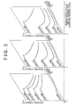
- FIG. 3 is a conceptual diagram showing the required torque setting maps according to the embodiment
- FIG. 4A and FIG. 4B are illustrative diagrams that shows some more specific examples of the required torque setting maps according to the embodiment.
- FIG. 4A is a map for when the vehicle speed Vtmp is zero
- FIG. 4B is a map for when the vehicle speed Vtmp is comparatively high.
- These maps are used to set the required torque Tr* that is output from the ring gear shaft 32a.
- the maps are 3-dimensional maps that correspond to different vehicle speeds Vtmp at the time of a request for increased driving force.
- the maps show a determined relationship between the accelerator opening degree Acc, the vehicle speed V, and the required torque Tr*. Note that, due to limitation of space, FIG. 3 only shows three example maps corresponding to different vehicle speeds Vtmp.
- the maps are set such that the required torque Tr* is generally greater with respect to the same accelerator opening degree Acc when the vehicle speed Vtmp is low, than when the vehicle speed Vtmp is high. Accordingly, if the driver wants to accelerate when the vehicle speed is low, the required torque Tr* that is set as a result of depressing the accelerator pedal is large. In other words, the map of FIG. 4A is set to meet the driver's request for increased acceleration when the vehicle speed Vtmp is near zero. Further, the required torque setting map for when the vehicle speed Vtmp is high ( FIG.
- the required torque Tr* generally changes a small amount with respect to changes in the accelerator opening degree Acc in a high speed region when the accelerator opening degree is varied between substantially 0% and 75%.
- the map is set such that even if the driver changes the accelerator opening degree Acc a little, the required torque Tr* does not change a large amount.
- the vehicle speed Vtmp is high ( FIG. 4B )
- the vehicle speed Vtmp is low (refer to FIG.
- the required torque Tr* is set to be constant for the same accelerator opening degree Acc in the high speed region. Accordingly, with the map of FIG. 4A , if the driver has accelerated to a higher vehicle speed V, it is necessary for the driver to increase the accelerator opening degree Acc in order to hold the required torque Tr* at a constant level. However, the map of FIG. 4B is set such that, even if the driver has accelerated to a higher vehicle speed V, the same accelerator opening degree Acc causes a constant driving force to be output from the drive shaft. In other words, the map of FIG.
- step S120 when the previous accelerator opening degree Acc is not zero, or, when the accelerator opening degree Acc in step S110 is zero, the CPU 72 selects the required torque setting map used in the previous processing cycle as the required torque setting map (step S 130).
- the CPU 72 uses the selected map to set the required torque (required driving force) Tr* that needs to be output to the ring gear shaft 32a, and a required engine power Pe* needed by the vehicle (step S160).
- the required torque Tr* is derived and set using the selected map as the required torque Tr* that corresponds to the given accelerator opening degree Acc and vehicle speed V.
- the rotation speed Nr of the ring gear shaft 32a may be derived by multiplying the vehicle speed V by conversion factor k, or may be derived by dividing the rotation speed Nm2 of the motor MG 2 by a gear ratio Gr of the reduction gear 35.
- the charge/discharge required power Pb* is basically set such that the SOC of the battery 46 becomes an appropriate value (for example, 60 to 70%).
- the CPU 72 sets a target rotational speed Ne* and a target torque Te* for the engine 20 using the set required engine power Pe* (step S 170).
- the target rotational speed Ne* and the target torque Te* are set based on an operating line that indicates efficient operation of the engine 20, and the required engine power Pe*.
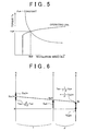
- FIG. 5 shows one example of the operating line of the engine 20 and setting of the target rotational speed Ne* and the target torque Te*.
- the target rotational speed Ne* and the target torque Te* are derived from the intersection of the operating line and the curve indicating the engine required power Pe*.
- step S180 Expression (1) is used to set a target rotation speed Nm1* of the motor MG 1 using the target rotational speed Ne* of the engine 20, the rotation speed Nr (Nm2/Gr) of the ring gear shaft 32a, and a gear ratio p (i.e., the teeth number of the sun gear 31/the teeth number of the ring gear 32) of the power distribution/integration mechanism 30.
- Expression (2) is used to set the target torque Tm1* of the motor MG 1 using the set target rotational speed Nm1* and the present rotation speed Nm1.
- Expression (1) is an expression that indicates the dynamic relationship of the rotating elements of the power distribution/integration mechanism 30. FIG.
- FIG. 6 is an alignment chart that explains the dynamic relationship of the torque and the rotation speed of the rotating elements of the power distribution/integration mechanism 30.
- the shaft S on the left indicates the rotation speed of the sun gear 31 that is the rotation speed Nm1 of the motor MG 1
- the shaft C indicates the rotation speed of the carrier 34 that is the rotational speed Ne of the engine 20
- the shaft R indicates the rotation speed Nr of the ring gear 32.
- Expression (1) can easily be derived using this alignment chart.
- Expression (2) is an expression showing a relationship used in feedback control that controls the motor MG 1 to rotate at the target rotation speed Nm1*.
- "k1" of the second term on the right side is a proportional term gain
- "k2" of the third term on the right side is an integral term gain.
- the CPU 72 sets the target torque Tm2* of the motor MG 2 (step S 190).
- the target torque Tm2* is set within the range of the input/output limit values Win, Wout of the battery 46. More specifically, when calculating the target torque Tm2*, torque limits Tmin and Tmax are calculated using Expression (3) and Expression (4), and then a provisional motor torque Tm2tmp is calculated using Expression (5) that uses the required torque Tr*, the target torque Tm1*, and the gear ratio p of the power distribution/integration mechanism 30.
- the provisional motor torque Tm2tmp indicates the torque that needs to be output from the motor MG 2.
- the provisional motor torque Tm2tmp is set within the constraints of the calculated torque limits Tmin and Tmax.
- Tmin Win - Tm ⁇ 1 * ⁇ Nm ⁇ 1 / Nm ⁇ 2
- Tmax Wout - Tm ⁇ 1 * ⁇ Nm ⁇ 1 / Nm ⁇ 2
- Tm ⁇ 2 ⁇ tmp Tr * + Tm ⁇ 1 * / ⁇ / Gr
- the CPU 72 commands the engine ECU 50 to perform control of the target rotational speed Ne* and the target torque Te* of the engine 20, and commands the motor ECU 40 to perform control of the target torques Tm1* and Tm2* of the motors MG 1 and MG 2 (step S200).
- the drive control routine is ended.
- the engine ECU 50 Upon receiving the command from the CPU 72, the engine ECU 50 performs controls like fuel injection control and ignition control of the engine 20 so that it operates at the operating point indicated by the target rotational speed Ne* and the target torque Te*.
- the motor ECU 40 when the motor ECU 40 receives the command from the CPU 72, the motor ECU 40 performs switching control of the inverters 41 and 42 so that the motor MG 1 is driven based on the target torque Tm1*, and the motor MG 2 is driven based on the target torque Tom2*.
- FIG. 4A and FIG. 4B will be used to explain the series of operations in the drive control routine shown in FIG. 2 .
- the explanation given here will focus on an example in which the hybrid vehicle 10 starts running from a stopped state.
- the accelerator pedal 83 which is fully released when the vehicle is stopped, the accelerator opening degree Acc increases from zero.
- the required torque Tr* is set based on the present accelerator opening degree Acc and the present vehicle speed V, and the engine 20 and the motors MG 1 and MG 2 are controlled so that the set required torque Tr* is output to the ring gear shaft 32a that functions as the drive shaft.
- the map used at this time is selected while prioritizing the fact that the driver is accelerating from a vehicle speed V in the vicinity of zero. Accordingly, a large torque is output with respect to the accelerator opening degree Acc, and the vehicle accelerates responsively.
- the vehicle accelerates up to a comparatively high speed (for example, around 60 km/hour) and cruises at that speed. Then, the driver releases the accelerator pedal 83 in order to adjust acceleration or the like.
- the driver's sense of the relationship of the depression amount (i.e., the accelerator opening degree Acc) of the accelerator pedal 83 and the vehicle's feeling of acceleration is, in effect, "lost” or "confused".
- the accelerator opening degree Acc increases from zero.
- the CPU 72 determines that there is a request for increased driving force, sets the present vehicle speed as the vehicle speed Vtmp, and switches to the map that corresponds to this vehicle speed Vtmp (refer to FIG. 4B ).
- the required torque Tr* is then set based on the present accelerator opening degree Acc and the present vehicle speed V, and the engine 20 and the motors MG 1 and MG 2 are controlled so that the set required torque Tr* is output to the ring gear shaft 32a that acts as the drive shaft.
- the CPU 72 switches the maps when the vehicle accelerates again, the driver's sense of confusion/frustration is reduced even though his/her sense of the relationship of the vehicle's feeling of acceleration and depression of the accelerator pedal 83 has been lost by releasing the accelerator pedal 83.
- the CPU 72 uses the selected map corresponding to the vehicle speed Vtmp to set the required torque Tr* based on the present accelerator opening degree Acc and the vehicle speed V.
- This map is set such that, when the vehicle is cruising at a constant high speed, even if the driver changes the accelerator opening degree Acc a little, the required torque Tr* does not change a large amount. Accordingly, the driver will not be irritated by having to delicately adjust the depression amount of the accelerator pedal 83 in order to maintain a constant cruising speed.
- the torque is set constantly even if the depression amount of the accelerator pedal 83 is not increased.
- the driver has the sensation that the vehicle will accelerate forward responsively if he/she depresses the accelerator pedal 83 further.
- the CPU 72 controls running of the vehicle based on the selected map that corresponds to the vehicle speed Vtmp.
- the vehicle speed Vtmp at the time of the request for increased driving force is derived, and the required torque Tr* is set based on the derived vehicle speed Vtmp, the present accelerator opening degree Acc, and the present vehicle speed V.
- the engine 20 and the motors MG 1 and MG 2 are then controlled based on the set required torque Tr*, and driving force is output to the ring gear shaft 32a that serves as the drive shaft.
- the request of the driver is closely correlated to the vehicle speed Vtmp at the time of the request for increased driving force. Accordingly, the vehicle can be driven with a driving force that corresponds to the vehicle speed Vtmp at the time of the request for increased driving force, and as a result, as far as possible, driving force can be output that accords with the driver's request.
- the presently used required torque setting map is switched. As a result of switching the map in this manner, it is possible to reduce the driver's feeling of confusion or frustration. Moreover, because it is determined that there is a request for increased driving force when the accelerator opening degree Acc is increased from zero, it is comparatively easy to determine when the driver is requesting increased driving force.
- the required torque setting maps shown in FIGS. 3 , 4A and 4B are utilized to set the required torque Tr* based on the vehicle speed Vtmp, the present accelerator opening degree Acc, and the present vehicle speed V.
- an expression showing the relationship of the vehicle speed Vtmp, the present accelerator opening degree Acc, and the present vehicle speed V may be stored in advance in the ROM 74, and this expression may be used to calculate and derive the required torque Tr*.
- driving force can be output, as far as possible, in accordance with the driver's request.
- the required torque setting map that corresponds to the current vehicle speed Vtmp is selected (steps S140, S150).
- the accelerator change amount ⁇ Acc is calculated based on the difference between the accelerator opening degree Acc input in step S100, and the accelerator opening degree (previous Acc) input during the previous cycle of the routine (step S210). Then, it is determined whether the calculated accelerator change amount ⁇ Acc is equal to or more than the threshold value Aref (step S220).
- the threshold value Aref is a value for determining whether an increase in acceleration has been requested, and may be set, for example, at 20%, 30% or 40%.
- step S 130 when the accelerator change amount ⁇ Acc is below the threshold value Aref, step S 130 and the following steps of the drive control routine are performed. With this configuration as well, it is possible to output driving force, as far as possible, in accordance with the driver's request. Moreover, the processing of steps S210 and S220 shown in FIG. 7 may be performed after step S 120 of the drive control routine of FIG. 2 . If this configuration is adopted, the CPU 72 determines that there is a request for increased driving force when either (i) the accelerator opening degree Acc has increased from zero, and/or (ii) the accelerator change amount ⁇ Acc has become equal to or more than the threshold value Aref.
- driving force of the motor MG 2 is output to the ring gear 32.
- the output of the motor MG 2 may be directed to a shaft (the shaft of wheels 63B, 63B in FIG. 8 ) other than the shaft coupled to the ring gear 32 (i.e., the shaft of the driven wheels 63, 63), as in a hybrid vehicle 10B shown in FIG. 8 .
- output of the engine 20 is output to the ring gear 32 coupled to the driven wheels 63 via the power distribution/integration mechanism 30.
- a configuration like that of a hybrid vehicle 10C shown in FIG. 9 may be adopted instead.
- a two-rotor motor 90 is provided including an inner rotor 91 connected to the crankshaft 27 of the engine 20 and an outer rotor 92 connected to the drive shaft that outputs driving force to the driven wheels 63 and 63.
- the two-rotor motor 90 transmits part of the power of the engine 20 to the drive shaft, and converts the remaining power to electric power.
- the hybrid vehicle 10 combines features of both series and parallel hybrid systems.
- the invention may be applied to a vehicle that is purely a series hybrid or a parallel hybrid.
- the invention may be applied to any type of vehicle, such as, for example, the automobile 10D shown in FIG. 10 in which a stepless transmission 97 (e.g., a CVT or a toroidal transmission) is connected to the crank shaft 27 that is the output shaft of the engine 20 via a torque converter 96.
- a stepless transmission 97 e.g., a CVT or a toroidal transmission
- the invention may be applied to an electric vehicle including a battery that stores electric power, and a motor that converts electric power supplied from the battery to mechanical power and outputs this power to a drive shaft.
- the invention may also be utilized in a fuel cell hybrid vehicle that includes (i) a fuel cell (for example, a solid polymer electrolyte fuel cell) in which a fuel gas, namely, hydrogen, is reacted with an oxidizing gas, namely, air, to generate electric power, (ii) a battery that stores the electric power, and (iii) a motor that converts the electric power supplied from the battery to mechanical power and outputs it to a drive shaft.
- a fuel cell for example, a solid polymer electrolyte fuel cell
- a fuel gas namely, hydrogen
- an oxidizing gas namely, air
Landscapes
- Engineering & Computer Science (AREA)
- Transportation (AREA)
- Mechanical Engineering (AREA)
- Chemical & Material Sciences (AREA)
- Combustion & Propulsion (AREA)
- Power Engineering (AREA)
- Automation & Control Theory (AREA)
- Electric Propulsion And Braking For Vehicles (AREA)
- Hybrid Electric Vehicles (AREA)
- Control Of Driving Devices And Active Controlling Of Vehicle (AREA)
- Control Of Vehicle Engines Or Engines For Specific Uses (AREA)
- Auxiliary Drives, Propulsion Controls, And Safety Devices (AREA)
Abstract
Claims (13)
- Dispositif de sortie d'énergie qui délivre en sortie une force d'entraînement d'une source d'énergie à un arbre d'entraînement, comprenant :un moyen (84) de détection de degré d'ouverture d'accélérateur destiné à détecter un degré d'ouverture d'accélérateur (Acc) d'un accélérateur actionné par un conducteur ;un moyen (88) de détection de vitesse de véhicule destiné à détecter la vitesse d'un véhicule ;un moyen (70) de réglage de force d'entraînement nécessaire destiné à régler une force d'entraînement nécessaire (Tr*) lorsque le conducteur a demandé une force d'entraînement accrue tel qu'on le détermine selon le degré d'ouverture d'accélérateur (Acc) détecté par le moyen (84) de détection de degré d'ouverture d'accélérateur, en dérivant une vitesse (Vtmp) de véhicule au moment de la requête pour une force d'entraînement accrue, et à régler la force d'entraînement nécessaire (Tr*) sur la base de la vitesse dérivée (Vtmp) de véhicule au moment de la requête pour une force d'entraînement accrue, du degré actuel d'ouverture d'accélérateur (Acc), et d'une vitesse actuelle (V) de véhicule ; etun moyen de commande (40, 50) destiné à commander la source d'énergie (20, MG 1, MG 2) sur la base de la force d'entraînement nécessaire (Tr*) réglée par le moyen (70) de réglage de force d'entraînement nécessaire, oùle moyen (70) de réglage de force d'entraînement nécessaire détermine que le conducteur a demandé une force d'entraînement accrue lorsqu'une quantité de changement (ΔAcc) du degré d'ouverture d'accélérateur (Acc) est supérieure ou égale à une quantité de changement d'exigence de réglage prédéterminée (Aref).
- Dispositif de sortie d'énergie selon la revendication 1, dans lequel
lorsque la force d'entraînement nécessaire (Tr*) est réglée, le moyen (70) de réglage de force d'entraînement nécessaire règle la force d'entraînement nécessaire (Tr*) en utilisant une relation tridimensionnelle prédéterminée du degré d'ouverture d'accélérateur (Acc), de la vitesse (V) de véhicule, et de la force d'entraînement nécessaire (Tr*), la relation tridimensionnelle correspondant à la vitesse (Vtmp) de véhicule au moment de la requête pour une force d'entraînement accrue. - Dispositif de sortie d'énergie selon la revendication 2, dans lequel
lorsqu'il y a une requête pour une force d'entraînement accrue, le moyen (70) de réglage de force d'entraînement nécessaire passe de la relation tridimensionnelle actuellement utilisée à une relation tridimensionnelle correspondant à la vitesse (Vtmp) de véhicule au moment de la requête pour une force d'entraînement accrue. - Dispositif de sortie d'énergie selon l'une quelconque des revendications 1 à 3, dans lequel
le moyen (70) de réglage de force d'entraînement nécessaire détermine que le conducteur a demandé une force d'entraînement accrue lorsque le degré d'ouverture d'accélérateur (Acc) a augmenté essentiellement de zéro. - Dispositif de sortie d'énergie selon l'une quelconque des revendications 1 à 4, dans lequel
lorsque la force d'entraînement nécessaire est réglée, le moyen (70) de réglage de force d'entraînement nécessaire règle la force d'entraînement nécessaire (Tr*) de façon à ce qu'elle soit plus grande par rapport au même degré d'ouverture d'accélérateur (Acc) lorsque la vitesse (Vtmp) de véhicule est basse lorsqu'il y a une requête pour une force d'entraînement accrue, tel que comparé au moment où la vitesse (Vtmp) de véhicule est élevée lorsqu'il y a une requête pour une force d'entraînement accrue. - Dispositif de sortie d'énergie selon l'une quelconque des revendications 1 à 5, dans lequel
lorsque la force d'entraînement nécessaire (Tr*) est réglée, le moyen (70) de réglage de force d'entraînement nécessaire règle la force d'entraînement nécessaire (Tr*) de façon à ce que, si la vitesse (Vtmp) de véhicule est élevée lorsqu'il y a une requête pour une force d'entraînement accrue, la force d'entraînement nécessaire (Tr*) change moins par rapport à un changement donné du degré d'ouverture d'accélérateur (Acc) dans une région à vitesse élevée. - Dispositif de sortie d'énergie selon l'une quelconque des revendications 1 à 6, dans lequel
lorsque la force d'entraînement nécessaire (Tr*) est réglée, le moyen (70) de réglage de force d'entraînement nécessaire règle la force d'entraînement nécessaire (Tr*) de façon à ce que, si la vitesse (Vtmp) de véhicule est élevée lorsqu'il y a une requête pour une force d'entraînement accrue tel que comparé au moment où la vitesse (Vtmp) de véhicule est basse lorsqu'il y a une requête pour une force d'entraînement accrue, la force d'entraînement nécessaire (Tr*) est essentiellement constante par rapport au même degré d'ouverture d'accélérateur (Acc) dans la région à vitesse élevée. - Dispositif de sortie d'énergie selon l'une quelconque des revendications 1 à 7, dans lequel
la source d'énergie est un moteur à combustion interne (20) qui délivre en sortie l'énergie à un arbre de sortie, et le dispositif de sortie d'énergie comprend en outré :un moyen (30, 35, MG 1, MG 2) de transmission/changement de vitesse relié à l'arbre de sortie, pour changer la vitesse de rotation de la sortie d'énergie de l'arbre de sortie conformément à un changement dans un rapport d'engrenage continuellement variable, et pour transmettre l'énergie à l'arbre d'entraînement d'une roue de véhicule, oùle moyen de commande (40, 50) commande le moteur à combustion interne (20) et le moyen (30, 35, MG 1, MG 2) de transmission/changement de vitesse sur la base de la force d'entraînement nécessaire (Tr*) réglée par le moyen (70) de réglage de force d'entraînement nécessaire. - Dispositif de sortie d'énergie selon l'une quelconque des revendications 1 à 7, dans lequel
la source d'énergie est prévue dans une pluralité, l'une des sources d'énergie étant un moteur à combustion interne (20) qui délivre en sortie l'énergie à l'arbre d'entraînement, et une autre des sources d'énergie étant un moteur qui peut introduire au choix l'énergie à l'arbre d'entraînement et délivrer en sortie l'énergie de l'arbre d'entraînement, et le dispositif de sortie d'énergie comprend en outre :un moyen (30, MG 1) d'entrée-sortie d'énergie, relié à l'arbre de sortie et à l'arbre d'entraînement d'une roue de véhicule, pour délivrer en sortie au moins une partie de l'énergie délivrée en sortie du moteur à combustion interne (20) à l'arbre d'entraînement, oùle moyen de commande (40, 50) commande le moteur à combustion interne (20), le moyen (30, MG 1) d'entrée-sortie d'énergie et le moteur (MG 2) sur la base de la force d'entraînement nécessaire (Tr*) réglée par le moyen (70) de réglage de force d'entraînement nécessaire. - Dispositif de sortie d'énergie selon la revendication 9, dans lequel le moyen (30) d'entrée-sortie d'énergie comporté :un moyen (30) de transfert d'énergie à trois arbres, ayant trois arbres qui sont reliés à trois arbres de sortie respectifs qui forment l'arbre de sortie du moteur à combustion interne (20), à l'arbre d'entraînement, et à un troisième arbre de rotation, pour transférer au choix l'énergie entre deux quelconques des trois arbres et l'arbre restant de façon à ce que les deux arbres introduisent l'énergie lorsque l'arbre restant délivre en sortie l'énergie ou de façon à ce que les deux arbres délivrent en sortie l'énergie lorsque l'arbre restant introduit l'énergie ; etun générateur (MG 1) qui transfère l'énergie à/depuis le troisième élément de rotation, oùle moyen de commande (40, 50) commande le moteur à combustion interne (20), le générateur (MG 1) et le moteur (MG 2) sur la base de la force d'entraînement nécessaire (Tr*) réglée par le moyen (70) de réglage de force d'entraînement nécessaire.
- Dispositif de sortie d'énergie selon la revendication 9, dans lequel
le moyen (30, MG 1) d'entrée-sortie d'énergie est un moteur à deux rotors muni d'un premier rotor relié à l'arbre de sortie du moteur à combustion interne (20) et d'un deuxième rotor relié à l'arbre d'entraînement, le moteur à deux rotors transférant l'énergie électrique générée par l'effet électromagnétique du premier rotor et du deuxième rotor, et délivrant en sortie au moins une partie de l'énergie du moteur à combustion interne (20) à l'arbre d'entraînement. - Véhicule équipé du dispositif de sortie d'énergie selon l'une quelconque des revendications 1 à 11.
- Procédé pour commander un dispositif de sortie d'énergie qui délivre en sortie une force d'entraînement d'une source d'énergie à un arbre d'entraînement, comprenant le fait :de déterminer si un conducteur a demandé une force d'entraînement accrue sur la base d'un degré d'ouverture d'accélérateur (Acc), et lorsqu'on détermine que le conducteur a demandé une force d'entraînement accrue ;de détecter une vitesse de véhicule ;de dériver une vitesse (Vtmp) de véhicule au moment de la requête pour une force d'entraînement accrue ;de régler une force d'entraînement nécessaire (Tr*) sur la base de la vitesse dérivée (Vtmp) de véhicule au moment de la requête pour une force d'entraînement accrue, du degré actuel d'ouverture d'accélérateur (Acc), et d'une vitesse actuelle (V) de véhicule ;de commander la source d'énergie (20, MG 1, MG 2) sur la base de la force d'entraînement nécessaire réglée (Tr*), etde déterminer que le conducteur a demandé une force d'entraînement accrue lorsqu'une quantité de changement (ΔAcc) du degré d'ouverture d'accélérateur (Acc) est supérieure ou égale à une quantité de changement d'exigence de réglage prédéterminée (Aref).
Applications Claiming Priority (2)
| Application Number | Priority Date | Filing Date | Title |
|---|---|---|---|
| JP2005047016A JP4529726B2 (ja) | 2005-02-23 | 2005-02-23 | 動力出力装置、動力出力装置の制御方法及びそれを搭載した車両 |
| PCT/IB2006/000359 WO2006103501A2 (fr) | 2005-02-23 | 2006-02-22 | Dispositif de production d'energie, procede de commande dudit dispositif et vehicule ainsi equipe |
Publications (2)
| Publication Number | Publication Date |
|---|---|
| EP1851082A2 EP1851082A2 (fr) | 2007-11-07 |
| EP1851082B1 true EP1851082B1 (fr) | 2011-05-18 |
Family
ID=36930159
Family Applications (1)
| Application Number | Title | Priority Date | Filing Date |
|---|---|---|---|
| EP06755823A Expired - Lifetime EP1851082B1 (fr) | 2005-02-23 | 2006-02-22 | Dispositif de sortie de puissance, procédé de commande dudit dispositif et véhicule ainsi équipé |
Country Status (5)
| Country | Link |
|---|---|
| US (1) | US7962257B2 (fr) |
| EP (1) | EP1851082B1 (fr) |
| JP (1) | JP4529726B2 (fr) |
| CN (1) | CN101115649B (fr) |
| WO (1) | WO2006103501A2 (fr) |
Families Citing this family (23)
| Publication number | Priority date | Publication date | Assignee | Title |
|---|---|---|---|---|
| JP4270275B2 (ja) * | 2006-12-26 | 2009-05-27 | トヨタ自動車株式会社 | 車両およびその制御方法 |
| JP4450027B2 (ja) * | 2007-07-18 | 2010-04-14 | トヨタ自動車株式会社 | 車両の制御装置および制御方法 |
| US8070647B2 (en) | 2007-11-05 | 2011-12-06 | GM Global Technology Operations LLC | Method and apparatus for adapting engine operation in a hybrid powertrain system for active driveline damping |
| EP2055591B1 (fr) * | 2007-11-05 | 2013-10-30 | GM Global Technology Operations LLC | Procédé et appareil pour adapter une opération de moteur dans un système de transmission hybride |
| JPWO2010052768A1 (ja) * | 2008-11-05 | 2012-03-29 | トヨタ自動車株式会社 | ハイブリッド車両の制御装置 |
| JP5203910B2 (ja) * | 2008-12-11 | 2013-06-05 | トヨタ自動車株式会社 | 目標駆動制御量設定算出装置、車両走行システム、目標駆動制御量設定方法 |
| JP5240079B2 (ja) * | 2009-06-09 | 2013-07-17 | トヨタ自動車株式会社 | 車両の制御装置 |
| JP5388303B2 (ja) * | 2010-03-25 | 2014-01-15 | 富士重工業株式会社 | 無段変速機の変速制御装置 |
| US8560144B2 (en) * | 2011-06-17 | 2013-10-15 | GM Global Technology Operations LLC | Output torque rate limiting based on a request busyness indicator that considers the recent time history of the output torque request |
| US9193278B2 (en) * | 2011-09-27 | 2015-11-24 | Toyota Jidosha Kabushiki Kaisha | Vehicle and method of controlling vehicle |
| EP2762375A4 (fr) * | 2011-09-27 | 2016-01-27 | Toyota Motor Co Ltd | Véhicule et procédé de commande pour véhicule |
| WO2013187464A1 (fr) * | 2012-06-13 | 2013-12-19 | 日産自動車株式会社 | Régulateur de force motrice pour véhicule |
| JP5862533B2 (ja) * | 2012-09-27 | 2016-02-16 | トヨタ自動車株式会社 | 車両および車両の制御方法 |
| JP6197414B2 (ja) * | 2013-07-04 | 2017-09-20 | 日産自動車株式会社 | 車両制御装置 |
| US9789873B2 (en) | 2014-02-16 | 2017-10-17 | Ford Global Technologies, Llc | Vehicle coasting control system and method |
| CN104842996B (zh) * | 2014-06-18 | 2017-10-10 | 北汽福田汽车股份有限公司 | 一种混合动力汽车换挡方法及系统 |
| CN104827931B (zh) * | 2014-07-29 | 2017-02-08 | 北汽福田汽车股份有限公司 | 电动汽车工作模式的控制方法、系统及具有其的电动汽车 |
| KR101637304B1 (ko) * | 2015-03-02 | 2016-07-07 | 현대자동차 주식회사 | 토크 지령 생성 방법 및 장치 |
| JP6489641B2 (ja) * | 2015-04-22 | 2019-03-27 | 国立大学法人東京海洋大学 | 船艇用モータの制御装置、制御方法、及び制御プログラム |
| CN108363344B (zh) * | 2017-10-24 | 2022-09-02 | 山东省农业机械科学研究院 | 基于云网络测控系统的农业机械可靠性试验方法 |
| JP7168439B2 (ja) * | 2018-12-20 | 2022-11-09 | トヨタ自動車株式会社 | 車両の制御装置 |
| JP7251461B2 (ja) * | 2019-12-13 | 2023-04-04 | トヨタ自動車株式会社 | 制御システム |
| WO2021251430A1 (fr) * | 2020-06-12 | 2021-12-16 | 株式会社アイシン | Dispositif d'entraînement de véhicule |
Citations (2)
| Publication number | Priority date | Publication date | Assignee | Title |
|---|---|---|---|---|
| JPH08196005A (ja) * | 1995-01-13 | 1996-07-30 | Nissan Motor Co Ltd | 電気自動車用モータの駆動制御装置 |
| JPH08218919A (ja) * | 1995-02-15 | 1996-08-27 | Hitachi Ltd | 駆動力制御方法 |
Family Cites Families (13)
| Publication number | Priority date | Publication date | Assignee | Title |
|---|---|---|---|---|
| JP2794272B2 (ja) * | 1995-02-28 | 1998-09-03 | 株式会社エクォス・リサーチ | ハイブリッド車両及びハイブリッド車両の制御方法 |
| JP3050125B2 (ja) | 1996-05-20 | 2000-06-12 | トヨタ自動車株式会社 | 動力出力装置および動力出力装置の制御方法 |
| JP3456624B2 (ja) | 1997-11-28 | 2003-10-14 | 本田技研工業株式会社 | ハイブリッド車両の制御装置 |
| CA2259771C (fr) | 1998-02-19 | 2003-04-01 | Hitachi, Ltd. | Transmission, ainsi que vehicule et bicyclette utilisant cette transmission |
| JP3451935B2 (ja) * | 1998-06-03 | 2003-09-29 | 日産自動車株式会社 | ハイブリッド車両の駆動力制御装置 |
| JP2000272380A (ja) * | 1999-03-24 | 2000-10-03 | Mitsubishi Motors Corp | 車両用制御装置 |
| US6528959B2 (en) | 2000-07-19 | 2003-03-04 | Honda Giken Kogyo Kabushiki Kaisha | Driving force control system for front-and-rear wheel drive vehicles |
| JP3578451B2 (ja) | 2001-07-23 | 2004-10-20 | 日産自動車株式会社 | 駆動装置 |
| JP3798728B2 (ja) | 2002-04-26 | 2006-07-19 | 株式会社ジェイテクト | 四輪駆動車の駆動力配分制御装置 |
| JP3770251B2 (ja) * | 2002-06-21 | 2006-04-26 | 日産自動車株式会社 | 車両用報知装置及びその方法 |
| JP3857669B2 (ja) | 2002-09-04 | 2006-12-13 | 日産自動車株式会社 | ハイブリッド変速機 |
| JP3817516B2 (ja) * | 2002-12-26 | 2006-09-06 | 本田技研工業株式会社 | ハイブリッド車両の駆動制御装置 |
| JP4202203B2 (ja) * | 2003-07-22 | 2008-12-24 | トヨタ自動車株式会社 | 動力出力装置およびその制御方法並びに自動車 |
-
2005
- 2005-02-23 JP JP2005047016A patent/JP4529726B2/ja not_active Expired - Fee Related
-
2006
- 2006-02-22 WO PCT/IB2006/000359 patent/WO2006103501A2/fr not_active Ceased
- 2006-02-22 US US11/883,023 patent/US7962257B2/en not_active Expired - Fee Related
- 2006-02-22 EP EP06755823A patent/EP1851082B1/fr not_active Expired - Lifetime
- 2006-02-22 CN CN2006800041382A patent/CN101115649B/zh not_active Expired - Fee Related
Patent Citations (2)
| Publication number | Priority date | Publication date | Assignee | Title |
|---|---|---|---|---|
| JPH08196005A (ja) * | 1995-01-13 | 1996-07-30 | Nissan Motor Co Ltd | 電気自動車用モータの駆動制御装置 |
| JPH08218919A (ja) * | 1995-02-15 | 1996-08-27 | Hitachi Ltd | 駆動力制御方法 |
Also Published As
| Publication number | Publication date |
|---|---|
| US20080119319A1 (en) | 2008-05-22 |
| JP4529726B2 (ja) | 2010-08-25 |
| JP2006233801A (ja) | 2006-09-07 |
| US7962257B2 (en) | 2011-06-14 |
| CN101115649A (zh) | 2008-01-30 |
| EP1851082A2 (fr) | 2007-11-07 |
| WO2006103501A3 (fr) | 2006-11-23 |
| WO2006103501A2 (fr) | 2006-10-05 |
| CN101115649B (zh) | 2010-08-25 |
Similar Documents
| Publication | Publication Date | Title |
|---|---|---|
| US7962257B2 (en) | Power output device, control method for the same, and vehicle equipped therewith | |
| US8849486B2 (en) | Vehicle and method of controlling the same | |
| JP4258548B2 (ja) | 車両およびその制御方法 | |
| JP4197037B2 (ja) | ハイブリッド自動車およびその制御方法 | |
| CN1809486B (zh) | 混合动力车辆及混合动力车辆控制方法 | |
| EP2227409B1 (fr) | Véhicule hybride et procédé de commande pour véhicule hybride | |
| EP1768868B1 (fr) | Appareil de production de puissance, moteur equipe d'un appareil de production de puissance et procede de commande de cet appareil de production de puissance | |
| EP1885589B1 (fr) | Vehicule hybride et sa methode de commande | |
| EP1809506B1 (fr) | Vehicule a moteur et methode de commande, en particulier pendant un retrogradage | |
| US7946956B2 (en) | Braking/driving force control device | |
| EP2103477A1 (fr) | Vehicule et son procede de controle | |
| JP2008162490A (ja) | ハイブリッド自動車およびその制御方法 | |
| JP4375417B2 (ja) | ハイブリッド自動車およびその制御方法 | |
| JP2008201383A (ja) | ハイブリッド自動車およびその制御方法 | |
| JP4055781B2 (ja) | ハイブリッド車およびその制御方法 | |
| JP3894184B2 (ja) | 自動車およびその制御方法 | |
| JP4259488B2 (ja) | 動力出力装置およびこれを搭載する車両並びにこれらの制御方法 | |
| JP4241710B2 (ja) | 車両およびその制御方法 | |
| JP2004343838A (ja) | 動力出力装置およびその制御方法並びに自動車 | |
| JP4597043B2 (ja) | 車両および駆動装置並びに車両の制御方法 | |
| JP2004346781A (ja) | 動力出力装置およびその制御方法並びに自動車 | |
| JP4215044B2 (ja) | ハイブリッド自動車およびその制御方法 | |
| JP2004136854A (ja) | ハイブリッド自動車およびその制御方法 | |
| JP2007216860A (ja) | 車両およびその制御方法 | |
| JP2018011429A (ja) | 自動車 |
Legal Events
| Date | Code | Title | Description |
|---|---|---|---|
| PUAI | Public reference made under article 153(3) epc to a published international application that has entered the european phase |
Free format text: ORIGINAL CODE: 0009012 |
|
| 17P | Request for examination filed |
Effective date: 20070821 |
|
| AK | Designated contracting states |
Kind code of ref document: A2 Designated state(s): DE FR GB |
|
| 17Q | First examination report despatched |
Effective date: 20071213 |
|
| DAX | Request for extension of the european patent (deleted) | ||
| RBV | Designated contracting states (corrected) |
Designated state(s): DE FR GB |
|
| GRAP | Despatch of communication of intention to grant a patent |
Free format text: ORIGINAL CODE: EPIDOSNIGR1 |
|
| RIC1 | Information provided on ipc code assigned before grant |
Ipc: B60W 10/06 20060101AFI20101018BHEP Ipc: B60W 10/08 20060101ALI20101018BHEP Ipc: B60W 20/00 20060101ALI20101018BHEP Ipc: B60K 6/445 20071001ALI20101018BHEP |
|
| RTI1 | Title (correction) |
Free format text: POWER OUTPUT DEVICE, CONTROL METHOD FOR THE SAME AND VEHICLE EQUIPPED THEREWITH |
|
| GRAS | Grant fee paid |
Free format text: ORIGINAL CODE: EPIDOSNIGR3 |
|
| GRAA | (expected) grant |
Free format text: ORIGINAL CODE: 0009210 |
|
| REG | Reference to a national code |
Ref country code: GB Ref legal event code: FG4D |
|
| REG | Reference to a national code |
Ref country code: DE Ref legal event code: R096 Ref document number: 602006022031 Country of ref document: DE Effective date: 20110630 |
|
| PLBE | No opposition filed within time limit |
Free format text: ORIGINAL CODE: 0009261 |
|
| STAA | Information on the status of an ep patent application or granted ep patent |
Free format text: STATUS: NO OPPOSITION FILED WITHIN TIME LIMIT |
|
| 26N | No opposition filed |
Effective date: 20120221 |
|
| REG | Reference to a national code |
Ref country code: DE Ref legal event code: R097 Ref document number: 602006022031 Country of ref document: DE Effective date: 20120221 |
|
| REG | Reference to a national code |
Ref country code: GB Ref legal event code: 746 Effective date: 20121112 |
|
| REG | Reference to a national code |
Ref country code: DE Ref legal event code: R084 Ref document number: 602006022031 Country of ref document: DE Effective date: 20121115 |
|
| PGFP | Annual fee paid to national office [announced via postgrant information from national office to epo] |
Ref country code: GB Payment date: 20130220 Year of fee payment: 8 Ref country code: FR Payment date: 20130301 Year of fee payment: 8 Ref country code: DE Payment date: 20130220 Year of fee payment: 8 |
|
| REG | Reference to a national code |
Ref country code: DE Ref legal event code: R119 Ref document number: 602006022031 Country of ref document: DE |
|
| GBPC | Gb: european patent ceased through non-payment of renewal fee |
Effective date: 20140222 |
|
| REG | Reference to a national code |
Ref country code: FR Ref legal event code: ST Effective date: 20141031 |
|
| REG | Reference to a national code |
Ref country code: DE Ref legal event code: R119 Ref document number: 602006022031 Country of ref document: DE Effective date: 20140902 |
|
| PG25 | Lapsed in a contracting state [announced via postgrant information from national office to epo] |
Ref country code: GB Free format text: LAPSE BECAUSE OF NON-PAYMENT OF DUE FEES Effective date: 20140222 Ref country code: FR Free format text: LAPSE BECAUSE OF NON-PAYMENT OF DUE FEES Effective date: 20140228 Ref country code: DE Free format text: LAPSE BECAUSE OF NON-PAYMENT OF DUE FEES Effective date: 20140902 |