EP1852165B1 - Automobile modêle réduit - Google Patents
Automobile modêle réduit Download PDFInfo
- Publication number
- EP1852165B1 EP1852165B1 EP06711881A EP06711881A EP1852165B1 EP 1852165 B1 EP1852165 B1 EP 1852165B1 EP 06711881 A EP06711881 A EP 06711881A EP 06711881 A EP06711881 A EP 06711881A EP 1852165 B1 EP1852165 B1 EP 1852165B1
- Authority
- EP
- European Patent Office
- Prior art keywords
- gear
- unit
- double
- rotating shaft
- model automobile
- Prior art date
- Legal status (The legal status is an assumption and is not a legal conclusion. Google has not performed a legal analysis and makes no representation as to the accuracy of the status listed.)
- Expired - Lifetime
Links
Images




Classifications
-
- A—HUMAN NECESSITIES
- A63—SPORTS; GAMES; AMUSEMENTS
- A63H—TOYS, e.g. TOPS, DOLLS, HOOPS OR BUILDING BLOCKS
- A63H17/00—Toy vehicles, e.g. with self-drive; ; Cranes, winches or the like; Accessories therefor
- A63H17/26—Details; Accessories
- A63H17/262—Chassis; Wheel mountings; Wheels; Axles; Suspensions; Fitting body portions to chassis
Definitions
- the present invention relates to a model automobile of four-wheel-drive type, and more specifically, to a chassis structure of a model automobile with a twin-shaft motor mounted as a midship engine.
- a midship engine vehicle having its engine mounted between wheel base has been commercially manufactured, including MR-S (trademark) manufactured by Toyota Motor Corporation and NSX (trademark) manufactured by Hyundai Motor Co., Ltd, for example. Because of the center of gravity located in a center of the chassis, the midship engine vehicle could provide an improved weight distribution between front and rear wheels toward a uniform distribution and thus an improved maneuverability of the vehicle. In addition, since the front or the rear portion of the chassis is not occupied by a driving system, therefore the flexibility in designing the vehicle, particularly in the front and the rear portions, could be increased.
- the model automobile as disclosed in the Four-wheel-drive mechanism of SLOT RACING by AUTOart has a twin-shaft motor mounted longitudinally in a center region of a chassis, specifically the motor mounted in such a manner that the motor rotating shafts are oriented toward the front and the rear directions, respectively, and further tip ends of respective rotating shafts extend up to near front and rear axles to allow pinion gears disposed in the tip ends of the rotating shafts to engage with crown gears attached to respective axles and thereby to allow the front and the rear axles to be rotated by the twin-shaft motor so as to drive the four wheels.
- the model automobile as disclosed in US-B1-6,231,422 which forms the basis for the preamble of claim 1 also embodies the one having a twin-shaft motor mounted longitudinally in a center region of a chassis, whose structure will be described in conjunction with Fig. 11 .
- a twin-shaft motor 102 is located substantially in a center region along the longitudinal direction of a vehicle body between a front axle 105 and a rear axle 106 in a chassis 101 and fixed in a center along the vehicle width direction as it is mounted longitudinally with a front rotating shaft 103 and a rear rotating shaft 104 extending therefrom toward the front and the rear, respectively.
- This twin-shaft motor 102 is oriented such that a power output axial line extends along the vehicle length direction and the power can be transmitted simultaneously to the front and to the rear.
- Two dry batteries are disposed side by side and in parallel with the twin-motor 102 placed therebetween, which dry batteries are connected in series with the twin-shaft motor 102 via a switch (not shown).
- a front driving mechanism connects the front rotating shaft 103 with the front axle 105 so as to transmit the power generated by the twin-shaft motor 102 to front wheels.
- the front driving mechanism illustrated herein comprises a front axle pinion 107, a front rotating shaft pinion 109, and a front power transmission gear (a front double-stage gear) comprising a front transmission pinion 112 and a front crown gear 111 mounted coaxially therewith.
- the front axle pinion 107 is fixed to the middle of the front axle 105 and rotatable around a horizontal axis in association with the front axle 105.
- the front rotating shaft pinion 109 is fixed to a front end of the front rotating shaft 103 and rotatable around a horizontal axis in association with the front rotating shaft 103.
- the front power transmission gear is disposed between the front axle 105 and the front rotating shaft 103 in the chassis 101 so as to be rotatable around the horizontal axis. In this configuration, the front axle pinion 107 engages with the front transmission pinion 112, while the front rotating shaft pinion 109 engages with the front crown gear 111, to thereby allow the power generated by the twin-shaft motor 102 to be transmitted to the front wheels.
- a rear driving mechanism connects the rear rotating shaft 104 with the rear axle 106 so as to transmit the power generated by the twin-shaft motor 102 to rear wheels.
- the rear driving mechanism illustrated herein comprises a rear axle pinion 108, a rear rotating shaft pinion 110, and a rear power transmission gear (a rear double-stage gear) comprising a rear transmission pinion 114 and a rear crown gear 113 mounted coaxially therewith.
- the rear axle pinion 108 is fixed to the middle of the rear axle 106 and rotatable around a horizontal axis in association with the rear axle 106.
- the rear rotating shaft pinion 110 is fixed to a rear end of the rear rotating shaft 104 and rotatable around a horizontal axis in association with the rear rotating shaft 104.
- the rear power transmission gear is disposed between the rear axle 106 and the rear rotating shaft 104 in the chassis 101 so as to be rotatable around the horizontal axis.
- the rear axle pinion 108 engages with the rear transmission pinion 114, while the rear rotating shaft pinion 110 engages with the rear crown gear 113, to thereby allow the power generated by the twin-shaft motor 102 to be transmitted to the rear wheels.
- front power transmission gear and the rear power transmission gear are disposed oppositely to each other.
- front driving mechanism and the rear driving mechanism have their gear ratios set equally. Since respective driving mechanisms have the configurations as described above, they can transmit the power generated by the twin-shaft motor 102 to the front and the rear wheels uniformly at the same time.
- the midship engine type model automobile according to the Four-wheel-drive mechanism of SLOT RACING by AUTOart has a drawback that since the rotating shafts of the twin-shaft motor are rather long and no member.is arranged for holding the positions of the rotating shaft tip ends and the respective gears rigidly, the motor rotating shafts could run off due to a torque from the gears during a high speed driving, leading to a deteriorated precision in meshing between pinion gears located at the tip ends of the rotating shafts and the crown gears attached to the axles, and eventually producing a loss of the motor driving power.
- the present invention is directed to a model automobile having a twin-shaft motor mounted in a midship engine layout, and an object thereof is to provide a model automobile comprising a chassis structure, in which the deformation of the chassis is reduced even during the high speed driving so that the meshing precision between respective gears would not be deteriorated.
- the present invention is also directed to a model automobile having a twin-shaft motor mounted in a midship engine layout, and another object thereof is to provide a model automobile comprising such a chassis structure that is made up of three units comprising a center unit, a front unit and a rear unit, all of which are made replaceable, and also that has a highly improved rigidity so as to inhibit the deteriorated meshing precision between the respective gears during the high speed driving even with the three unit type of chassis configuration.
- a model automobile of the present invention is intended to solve the problems as pointed above, and an invention as defined in claim 1.
- a model automobile of the present invention comprises a chassis that has been divided into three units, therefore a front unit and/or a rear unit are replaceable to other ones, allowing different units available as optional parts to be used for the respective units.
- a front unit or a rear unit that has an improved suspension and/or steering performance may be provided.
- a center unit may be replaced such that a light-weight center unit that employs a different size of battery can be used.
- the center unit includes driving mechanisms, such as the twin-shaft motor, the front and the rear rotating shaft gears, and the front and the rear double-stage gears, therefore those driving mechanisms mounted on the center unit side can be used commonly even after the front unit and/or the rear unit having been replaced by another.
- the invention as defined in claim 2 or 3 allows for the center unit and the front or the rear unit to be detachably interconnected, and also ensures that the connection can be held reliably by means of a snap-fitting.
- rigidity of a chassis around those sites of gears and gear housing is improved, so that deformation of the chassis during a high speed driving can be favorably prevented and thus meshing precision between the gears can be held in a proper condition.
- a model automobile of the present invention will now be described with reference to Figs. 1 to 10 .
- the term “front side” or “front” means the front direction with respect to a model vehicle
- the term “rear side” or “rear” means the rear direction with respect to the model vehicle
- the term “lateral side” means a lateral face of a chassis disposed intermediately between the front side and the rear side.
- the model automobile in the embodiment may run along a track having a right and a left sidewalls built along the track.
- Fig. 1 shows a top view of a chassis 1 of a model automobile in the present embodiment.
- Fig. 1 shows the chassis 1 in a condition where a sub-body, a gear cover 80 and a dressed top body have been removed, which will be described later in detail.
- chassis 1 of the model automobile comprises a center unit 10, a front unit 40 connected to a front portion of the center unit 10 and a rear unit 70 connected to a rear portion of the center unit 40.
- a twin-shaft motor 22 is mounted in a longitudinal orientation on a central region of the center unit 10, and the twin-shaft motor 22 has a front rotating shaft 23 in the front unit 40 side and a rear rotating shaft 33 in the rear unit 70 side.
- the chassis 1 is equipped with a front driving mechanism for transmitting a rotary driving force from the front rotating shaft 23-to front wheels 42.
- the front driving mechanism comprises a front rotating shaft pinion gear 25 adapted to rotate integrally with the front rotating shaft 23, a front double-stage gear 27 having a crown gear section adapted to operatively engage with the front rotating shaft pinion gear 25 so as to be rotated thereby, and a front axle spur gear 29 attached to the front axle 43 of the front wheels 42 and adapted to operatively engage with a spur gear section of the front double-stage gear 27 so as to be rotated integrally with the front axle 43.
- a front rotating shaft bevel gear (not shown) may be attached to the front rotating shaft 23, and further in this case, the front double-stage gear 27 may be configured as such a double-stage gear (not shown) that comprises a bevel gear section for engaging with said front rotating shaft bevel gear and a spur gear section for engaging with the front axle spur gear 29.
- the use of the bevel gear (conical gear) to transmit the power between the front rotating shaft 23 and the front double-stage gear 27 can provide a larger working area to improve a transmission efficiency and additionally help prevent any damages due to stress concentration.
- the chassis 1 is further equipped with a rear driving mechanism for transmitting a rotary driving force from the rear rotating shaft 33 to rear wheels 72.
- the rear driving mechanism comprises a rear rotating shaft pinion gear 35 adapted to rotate integrally with the rear rotating shaft 33, a rear double-stage gear 37 having a crown gear section adapted to operatively engage with the rear rotating shaft pinion gear 35 so as to be rotated thereby, and a rear axle spur gear 39 attached to the rear axle 73 of the rear wheels 72 and adapted to operatively engage with a spur gear section of the rear double-stage gear 37 so as to be rotated integrally with the rear axle 73.
- two batteries 24, such as size AA batteries are mounted in the left and the right sides, respectively, with respect to the twin-shaft motor 22 mounted in the center unit 10.
- a rear rotating shaft bevel gear (not shown) may be attached to the rear rotating shaft 33, and further in this case, the rear double-stage gear 37 may be configured as such a double-stage gear (not shown) that comprises a bevel gear section for engaging with said rear rotating shaft bevel gear and a spur gear section for engaging with the rear axle spur gear 39.
- the use of the bevel gear to transmit the power between the rear rotating shaft 33 and the rear double-stage gear 37 can provide a larger working area to improve the transmission efficiency and additionally help prevent any damages due to the stress concentration.
- FIG. 2 is a perspective view of the center unit 10 shown in the condition where the front unit 40, the rear unit 70, the twin-shaft motor 22, the front double-stage gear 27, the rear double-stage gear 37 and the batteries 24 having been removed from the chassis 1 of Fig. 1 .
- the center unit 10 defines a box configuration with an open top and comprises a motor housing 12 formed in the central region thereof, battery housings 14 formed in the left and the right sides with respect to the motor housing 12, a front double-stage gear housing 15 formed in the front side with respect to the motor housing 12 and having ribs for encompassing both lateral sides thereof, a rear double-stage gear housing 16 formed in the rear side with respect to the motor housing 12 and having ribs for encompassing both lateral sides thereof, a pair of front extensions 17 extending from the front portions of the left and the right battery housings 14 toward the front unit direction, and a pair of rear extensions 18 extending from the rear portions of the left and the right battery housing 14 toward the rear unit direction.
- a bearing section is formed in the front double-stage gear housing 15 to rotatably support the rotating shaft of the front double-stage gear 27, while another bearing section is formed in the rear double-stage gear housing 16 to rotatably support the rotating shaft of the rear double-stage gear 37.
- a total of four cylindrical front coupling protrusions 17a are formed in the pair of front extensions 17 for coupling the center unit 10 to the front unit 40, each of which is protruding downwardly and substantially vertically from a lower surface of said front extension 17.
- a front spur gear cover 17b is formed integrally with the center unit 10 for covering a part of an upper surface of the front axle spur gear 29 between the pair of front extensions 17.
- a pair of front extension slots 17c is formed in the pair of front extensions 17, into which a front snap-fitting, as will be described later, is engagingly locked.
- a total of four cylindrical rear coupling protrusions 18a are formed in the pair of rear extensions 18 for coupling the center unit 10 to the rear unit 70, each of which is protruding downwardly from a lower surface of said rear extension 18.
- a rear spur gear cover 18b is formed integrally with the center unit 10 for covering a part of an upper surface of the rear axle spur gear 39 between the pair of rear extensions 18.
- a pair of rear extension slots 18c is formed in the pair of rear extensions 18, into which a rear snap-fitting, as will be described later, is engagingly locked.
- Fig. 3(a) is a perspective view showing an assembled front unit 40
- Fig. 3(b) is a perspective view showing an exploded front unit 40.
- the front unit 40 comprises a front gear housing 44 having a peripheral rib and adapted to accommodate the front axle spur gear 29, a front bumper 46 formed in front of the front gear housing, and center unit couplings 48 formed in both lateral sides of the front gear housing 44.
- Four of front insertion holes 48a are formed in the center unit couplings 48, into which the front coupling protrusions 17a formed in the center unit 10 are inserted, respectively.
- a locking slot 49 is formed between the front bumper 46 and the front gear mounting 44 for engagingly locked with a front lock of a sub-body, which will be described later.
- a pair of front snap-fittings 44a is formed between the pair of center unit couplings 48, each of which is protruding upward and adapted to be inserted into and engagingly locked with the front extension slot 17c, when the front unit 40 is coupled with the center unit 10.
- the pair of front snap-fittings 44a has a hook-like (claw-like) shape and a portion of each hook for being locked is oriented toward the wheel 42 disposed outside of the front snap-fitting 44a (see Fig. 3(a) ).
- FIG. 4(a) is a perspective view showing an assembled rear unit 70
- Fig. 4(b) is a perspective view showing an exploded rear unit 70.
- the rear unit 70 comprises a rear gear housing 74 having a peripheral rib and adapted to accommodate the rear axle spur gear 39, center unit couplings 78 formed in both lateral sides of the rear gear housing 74, and a rear bumper 76 to be connected with the rear unit 70 via a pair of extension rear terminals extending from rear portions of the center unit couplings 78.
- rear insertion holes 78a are formed in the center unit couplings 78, into which the rear coupling protrusions 18a formed in the center unit 10 are inserted, respectively.
- a rear unit rear protrusion 79 is formed in a rear end face of the rear gear housing 74, and the rear unit rear protrusion 79 is aligned with a sub-body rear protrusion, which will be described later, and fastened with a body catch (a coupling ring), which will be also described later, to form an integrated body.
- a pair of rear snap-fittings 74a is formed between the pair of center unit couplings 78, each of which is protruding upward and adapted to be inserted into and engagingly locked with the rear extension slot 18c, when the rear unit 70 is coupled with the center unit 10.
- the pair of rear snap-fittings 74a has a hook-like (claw-like) shape and a portion of each hook for being locked is oriented toward the wheel 72 disposed outside of the rear snap-fitting 74a (see Fig. 4(a) ).
- FIG. 5(a) shows those three units that have been coupled to each other, in which as viewed in the front unit 40 side, the front coupling protrusions 17a of the center unit 10 are fittingly inserted into the front insertion holes 48a of the front unit 40 and additionally the front snap-fittings 44a are locked in the front extension slots 17c so as to ensure the coupling between the center unit 10 and the front unit 40.
- the chassis 1 is further mounted with a pair of batteries 24 and the twin-shaft motor 22 fitted with a motor mount from the above side with respect to the chassis 1.
- front double-stage gear 27 and the front axle spur gear 29 are enclosed with the front double-stage gear housing 15, the front spur gear cover 17b and the front gear housing 44 by connecting the front unit 40 to the center unit 10, and similarly the rear double-stage gear 37 and the rear axle spur gear 39 are enclosed with the rear double-stage gear housing 16, the rear spur gear cover 18c and the rear gear housing 29 (see Fig. 1 and Fig. 5(a) ). Further referring to Fig.
- the twin-shaft motor 22 is fitted with a front motor mount 51 from the front rotating shaft 23 side and a rear motor mount 52 from the rear rotating shaft 33 side.
- a bottom surface of the front motor mount 51 has a locking pawl, which is engagingly locked with a front bottom surface slot of the motor housing 12.
- a pair of snap-fittings are formed in the rear motor mount 52, which are oriented toward the lateral sides of the chassis 1 and adapted to be snap-fitted in a pair of rear bottom surface slots of the motor housing 12.
- the pair of snap-fittings disposed in the rear motor mount 52 can provide a sufficient resist by being engagingly locked with the pair of rear bottom surface slots.
- the motor mount is a two-piece structure comprising the front motor mount 51 and the rear motor mount 52 and functions to press the twin-shaft motor 22 against the center unit 10 in the front and the rear rotating shaft 22 and 33 sides.
- the twin-shaft motor 22 may probably exhibit a riotous behavior during the operation thereof, meaning that a torque may be generated, which could displace the twin-shaft motor 22 relative to the center unit 10, leading to the deteriorated stability.
- the above-described motor mount is used in order to ensure that the motor is fixedly secured to the chassis.
- the gear cover 80 comprises a lattice section formed in a central region thereof for covering a top surface of the twin-shaft motor 22, a front gear cover section formed in the front relative to the lattice section, a rear gear cover section formed in the rear relative to the lattice section and battery holding elements protruding from near the rear gear cover toward respective lateral sides.
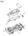
- Fig. 7 shows the gear cover 80 having been mounted over the chassis 1 of Fig. 6 .
- the chassis 1 is further fitted with a sub-body 83 that is mounted in the top surface side of the chassis 1 in order to improve rigidity of the assembled chassis 1.
- the sub-body 83 is an elongated box or plate-like member having a sub-body front lock 85 formed in a front end thereof and a sub-body rear protrusion 87 formed in a rear end thereof.
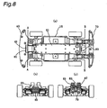
- the sub-body 83 To mount the sub-body 83 onto the chassis 1 of Fig. 7 , firstly, as the sub-body 83 is positioned over the chassis 1 so as to be held in parallel with the chassis 1, the sub-body front lock 85 of the sub-body 83 is locked (hooked) in the locking slot 49, and then a flat area on a bottom surface of the sub-body rear protrusion 87 and a flat area on a top surface of the rear unit rear protrusion 79 are brought into abutting contact to each other. As in the condition where the both components are aligned as described above, a body catch 89 (a holding member) is fitted over the both components from the rear side of the chassis 1.
- the body catch 89 has a substantially oval center slot configured to receive the rear unit rear protrusion 79 and the sub-body rear protrusion 87. Since the contour formed by the rear unit rear protrusion 79 and the sub-body rear protrusion 87 that are aligned with the body catch 89 is complementary to a shape of the substantially oval center slot, the rear unit rear protrusion 79 and the sub-body rear protrusion 87 (hereinafter referred to as the both components) can be mated with the oval center slot.
- the body catch can be rotated by 90 degrees, so that the both components can be fastened together as a major axial portion of the both components being held in a minor axial portion of the body catch 89. This condition is shown in Fig. 8(c) .
- the rigidity of the chassis 1 of the three-unit configuration can be improved and so a distortion of the chassis 1 during the high speed driving of the model automobile can be prevented, so that the meshing precision between respective gears can be improved and thereby the transmission efficiency of the rotary power and thus the battery life can be significantly increased.
- the sub-body includes a plurality of slots for fitting with a dressed body 90, and the sub-body 83 that has been previously fitted with the dressed body 90 is mounted on the chassis 1 to complete the model automobile.
- the sub-body 83 In the condition where the sub-body 83 having been securely attached as described above, the sub-body 83 is now positioned above and extending along the twin-shaft motor 22 and the respective gears of the front driving mechanism as well as the respective gears of the rear driving mechanism and functions to fasten those components as a whole from the front and the rear of the chassis, thus allowing the front and the rear driving mechanisms to be held rigidly by the sub-body 83.
- the chassis 1 of the model automobile in the illustrated embodiment comprises three units comprising the front unit 40, the center unit 10 and the rear unit 70 as described above, and configured to embody a wide range of chassis structures by replacing the front unit 40 and/or the rear unit 70 with other type of units relative to the center unit 10.
- Fig. 9 shows a side structural view depicting a wide variety of such chassis structures.
- Fig. 9(a) represents a chassis structure of standard vehicle type as described with respect to Figs. 1 to 8 .
- FIG. 9(b) represents a chassis structure of off-road vehicle type having a higher vehicle height as measured from a ground 90 over the standard vehicle, illustrating that in this chassis structure, a position for the front axle spur gear 29 of the front unit 40 to engage with the front double-stage gear 27 of the center unit 10 as well as a position of the front axle 43 (not shown) are located at a lower level as compared to Fig. 9(a) , and similarly a position for the rear axle spur gear 39 of the rear unit 70 to engage with the rear double-stage gear 37 of the center unit 10 as well as a position of the rear axle 73 (not shown) are located at a lower level as compared to Fig. 9(a) , and that the chassis is equipped with tires having a large diameter, as well.
- Fig. 9(c) represents a chassis structure of racing vehicle type having contrary a lower vehicle height as measured from the ground 90 over the standard vehicle, illustrating that in this chassis structure, the position for the front axle spur gear 29 of the front unit 40 to engage with the front double-stage gear 27 of the center unit 10 as well as the position of the front axle 43 (not shown) are located at a little higher level as compared to Fig. 9(a) , and similarly the position for the rear axle spur gear 39 of the rear unit 70 to engage with the rear double-stage gear 37 of the center unit 10 as well as the position of the rear axle 73 (not shown) are located at a little higher level as compared to Fig. 9(a) .
- Fig. 9(d) represents a chassis structure of specific type having different diameter of tires between the front tires and the rear tires, illustrating that in this chassis structure, the diameter of the front wheel 42 is smaller than that of the standard vehicle and the diameter of the rear wheel 72 is larger than that of the standard vehicle.
- Fig. 9(d) further illustrates that the position for the front axle spur gear 29 of the front unit 40 to engage with the front double-stage gear 27 of the center unit 10 as well as the position of the front axle 43 (not shown) are located at a little lower level as compared to Fig.
- Fig. 9(a) while the position for the rear axle spur gear 39 of the rear unit 70 to engage with the rear double-stage gear 37 of the center unit 10 as well as the position of the rear axle 73 (not shown) are located at a little higher level as compared to Fig. 9(a) .
- the front wheels of Fig. 9(d) employ one-way wheels as shown in Fig. 10 .
- Fig. 9(e) represents a chassis structure of a type having different gear ratio between the front axle side and the rear axle side, in which although the engaging positions of the gears are same as those in Fig. 9(a) , the gear ratio in the front axle side is 3.5:1, while the gear ratio in the rear axle side is 4:1.
- the rear wheels of Fig. 9(e) employ one-way wheels as shown in Fig. 10 .
- Fig. 10 shows generally a one-way wheel 91.
- Fig. 10(a) represents an exploded view of a wheel portion, illustrating that the one-way wheel 91 comprises a wheel portion 93 to be fitted with the front wheel 42 (the rear wheel 72), a center drive gear 95 to be connected to the axle, a pair of free pinions 97, and a gear housing 99 serving for accommodating the center drive gear 95 and the free pinion gear 97 and adapted to be fixedly received in the wheel 93.
- the one way wheel 91 having such a structure as described above, can function similarly to a differential gear. It is to be noted that the detailed description of the one-way wheel may be found in the Japanese Patent Publication No. Hei 6-98228 by the applicant of the present patents application.
- twin-shaft motor 22 is removable from the motor housing 14, therefore if the twin-shaft motor with the front and the rear rotating shaft pinion gear 25, 35.having the number of teeth equal to eight is used, the gear arrangement as indicated by No. 5 to No. 7 in Table 1 can be employed, so that a higher reduction ratio can be provided.
- Table 2 indicates a reduction ratio of a model automobile according to the cited document (manufactured by Autoartmodels) as previously mentioned in the article of Background Art. It is difficult with this model automobile to provide a high reduction ratio as compared to the embodiment of the present invention, because the model automobile of the cited document only use two gears, a pinion gear attached to a twin-shaft motor and a crown gear attached to an axle, for rotating wheels.
- the gear arrangement as indicated by No. 3 in Table 2 represents a predicted result, when the structure of the model automobile according to the cited document is applied to a model automobile in the same scale as the embodiment of the present invention for the purpose of comparison. It is structurally difficult to replace the gears in the No. 3 gear arrangement, but the possible gear combinations that can be modified by using the same chassis shows that providing a high reduction ratio is difficult as indicated by No. 1, No. 2, No. 4 and No. 5 without changing the pinion gears. It is to be assumed in Table 1 and Table 2 that when the gear arrangement is changed, the tire diameter is limited to 19mm.
- model automobile of the embodiment of the present invention is dividable into three units, therefore replacing the front and/or the rear units to other ones can easily modify even a suspension structure and it can also modify the vehicle length and/or the vehicle height.
- the model automobile according to the cited document has not allowed the engaging positions of the respective gears to be modified, whereas the embodiment of the present invention allows the engaging positions to be modified to the higher or the lower level as shown in Fig. 9(b) or Fig. 9(c) .
- the model automobile of the present invention can be shared in a wide range of vehicle types from ordinary vehicles to those specified for racings or rallies by using in common the same power unit as mounted in the center unit 10.
Landscapes
- Toys (AREA)
Abstract
Claims (14)
- Modèle réduit d'automobile comprenant un moteur à deux arbres (22) monté dans une région centrale d'un châssis (1), un mécanisme d'entraînement de roue avant relié à un arbre rotatif avant (23) dudit moteur à deux arbres et pouvant être mis en oeuvre pour entraîner des roues avant (42), et un mécanisme d'entraînement de roue arrière relié à un arbre rotatif arrière (33) dudit moteur à deux arbres et pouvant être mis en oeuvre pour entraîner des roues arrière (72), dans lequel ledit mécanisme d'entraînement de roue avant comprend : un engrenage d'arbre rotatif avant (25) attaché audit arbre rotatif avant ; un engrenage avant à double étage (27) relié en rotation audit engrenage d'arbre rotatif avant et un engrenage cylindrique d'axe de roue avant (29) entraîné pour tourner par ledit engrenage avant à double étage et ledit mécanisme d'entraînement de roue arrière comprend : un engrenage d'arbre rotatif arrière (35) attaché audit arbre rotatif arrière ; un engrenage arrière à double étage (37) relié en rotation audit engrenage d'arbre rotatif arrière ; et un engrenage cylindrique d'axe de roue arrière (39) entraîné pour tourner par ledit engrenage arrière à double étage, caractérisé en ce que
ledit châssis comprend : une unité de centre (10) définissant une partie centrale dudit châssis, sur lequel ledit moteur à deux arbres est monté ; une unité avant (40) définissant une partie avant dudit châssis, qui est reliée de façon amovible à ladite unité centrale et qui comprend lesdites roues avant ; et une unité arrière (70) définissant une partie arrière dudit châssis, qui est reliée de façon amovible à ladite unité de centre et qui comprend lesdites roues arrière ; dans lequel
ledit engrenage avant à double étage est installé dans ladite unité de centre ;
ledit engrenage cylindrique d'axe de roue avant est installé dans ladite unité avant ; et
ledit engrenage arrière à double étage est installé dans ladite unité de centre ; et
ledit engrenage cylindrique d'axe de roue arrière est installé dans ladite unité arrière. - Modèle réduit d'automobile selon la revendication 1, dans lequel, afin que ladite unité avant soit reliée de façon amovible à ladite unité de centre, ledit modèle réduit d'automobile comprend en outre : une pluralité de protubérances avant formées dans une extension avant da ladite unité de centre ; une pluralité de trous d'insertion avant formés dans ladite unité avant, dans lequel ladite pluralité de protubérances avant est insérée par ajustement ; une fente avant formée dans ladite extension avant de ladite unité de centre ; et un raccord à encliquetage avant formé dans ladite unité avant et conçu pour être inséré dans ladite fente avant de façon à fixer ladite unité avant à ladite unité centrale par encliquetage.
- Modèle réduit d'automobile selon la revendication 2, dans lequel comme dans l'état où ladite unité avant est reliée à ladite unité de centre, ladite pluralité de protubérances avant et ladite pluralité de trous d'insertion avant sont agencées de façon à respectivement enfermer ledit engrenage avant à double étage et ledit engrenage cylindrique d'axe de roue avant.
- Modèle réduit d'automobile selon la revendication 1 ou 2, dans lequel, afin que ladite unité arrière soit reliée de façon amovible à ladite unité de centre, ledit modèle réduit d'automobile comprend en outre : une pluralité de protubérances arrière formées dans une extension arrière de ladite unité centrale ; une pluralité de trous d'insertion arrière formés dans ladite unité arrière, dans laquelle ladite pluralité de protubérances arrière est insérée par ajustement ; une fente arrière formée dans ladite extension arrière de ladite unité de centre ; et un raccord à encliquetage arrière formé dans ladite unité arrière et conçu pour être inséré dans ladite fente arrière de façon à fixer ladite unité arrière à ladite unité de centre par encliquetage.
- Modèle réduit d'automobile selon la revendication 4, dans lequel, comme dans l'état où ladite unité arrière est reliée à ladite unité de centre, ladite pluralité de protubérances arrière et ladite pluralité de trous d'insertion arrière sont agencées de façon à respectivement enfermer ledit engrenage arrière à double étage et ledit engrenage cylindrique d'axe de roue arrière.
- Modèle réduit d'automobile selon l'une quelconque des revendications 1, 2, 4, dans lequel ledit modèle réduit d'automobile comprend en outre un logement d'engrenage avant à double étage ayant une nervure périphérique et conçu pour loger en rotation ledit engrenage avant à double étage dans ladite unité de centre et un logement d'engrenage avant ayant une nervure périphérique et conçu pour loger en rotation ledit engrenage cylindrique d'axe de roue avant dans ladite unité avant, et
dans lequel ledit engrenage avant à double étage et ledit engrenage cylindrique d'axe de roue avant sont respectivement enfermés dans ledit logement d'engrenage avant à double étage et ledit logement d'engrenage avant, en reliant ladite unité avant à ladite unité de centre. - Modèle réduit d'automobile selon l'une quelconque des revendications 1, 2, 4, 6, dans lequel ledit modèle réduit d'automobile comprend en outre un logement d'engrenage arrière à double étage ayant une nervure périphérique et conçu pour loger en rotation ledit engrenage arrière à double étage dans ladite unité de centre et un logement d'engrenage arrière ayant une nervure périphérique et conçu pour loger en rotation ledit engrenage cylindrique d'axe de roue arrière dans ladite unité arrière, et
dans lequel ledit engrenage arrière à double étage et ledit engrenage cylindrique d'axe de roue arrière sont respectivement enfermés dans ledit logement d'engrenage arrière à double étage et ledit logement d'engrenage arrière, en reliant ladite unité arrière à ladite unité de centre. - Modèle réduit d'automobile selon l'une quelconque des revendications 1, 4, 6, 7, dans lequel ledit modèle réduit d'automobile comprend en outre une pluralité de protubérances avant formées dans une extension avant de ladite unité de centre et une pluralité de trous d'insertion avant formés dans ladite unité avant, dans laquelle ladite pluralité de protubérances avant est insérée par ajustement, et
dans lequel comme dans l'état où ladite unité avant est reliée à ladite unité de centre, ladite pluralité de protubérances avant et ladite pluralité de trous d'insertion avant sont agencées de façon à respectivement enfermer ledit engrenage avant à double étage et ledit engrenage cylindrique d'axe de roue avant. - Modèle réduit d'automobile selon l'une quelconque des revendications 1, 2, 6-8, dans lequel ledit modèle réduit d'automobile comprend en outre une pluralité de protubérances arrière formées dans une extension arrière de ladite unité de centre et une pluralité de trous d'insertion arrière formés dans ladite unité arrière, dans laquelle ladite pluralité de protubérances arrière est insérée par ajustement, et
dans lequel, comme dans l'état où ladite unité arrière est reliée à ladite unité de centre, ladite pluralité de protubérances arrière et ladite pluralité de trous d'insertion arrière sont agencées de façon à respectivement enfermer ledit engrenage arrière à double étage et ledit engrenage cylindrique d'axe de roue arrière. - Modèle réduit d'automobile selon l'une quelconque des revendications 1-9, dans lequel ledit modèle réduit d'automobile comprend en outre un corps secondaire pour maintenir ladite unité de centre, ladite unité avant et ladite unité arrière d'un seul tenant comme ladite unité avant et ladite unité arrière sont reliées à ladite unité de centre.
- Modèle réduit d'automobile selon l'une quelconque des revendications 1-10, dans lequel ledit engrenage d'arbre rotatif avant est un engrenage à pignons d'arbre rotatif avant ; et
dans lequel ledit engrenage avant à double étage comprend une section d'engrenage plat pour mettre en prise ledit engrenage à pignons d'arbre rotatif avant et une section d'engrenage cylindrique pour mettre en prise ledit engrenage cylindrique d'axe avant. - Modèle réduit d'automobile selon l'une quelconque des revendications 1-11, dans lequel ledit engrenage d'arbre rotatif avant est un engrenage conique d'arbre rotatif avant ; et
dans lequel ledit engrenage avant à double étage comprend une section d'engrenage conique pour mettre en prise ledit engrenage conique d'arbre rotatif avant et une section d'engrenage cylindrique pour mettre en prise ledit engrenage cylindrique d'axe avant. - Modèle réduit d'automobile selon l'une quelconque des revendications 1-12, dans lequel ledit engrenage d'arbre rotatif arrière est un engrenage à pignons d'arbre rotatif arrière ; et
dans lequel ledit engrenage arrière à double étage comprend une section d'engrenage plat pour mettre en prise ledit engrenage à pignons d'arbre rotatif arrière et une section d'engrenage cylindrique pour mettre en prise ledit engrenage cylindrique d'axe arrière. - Modèle réduit d'automobile selon l'une quelconque des revendications 1-13, dans lequel ledit engrenage d'arbre rotatif arrière est un engrenage conique d'arbre rotatif arrière ; et
dans lequel ledit engrenage arrière à double étage comprend une section d'engrenage conique pour mettre en prise ledit l'engrenage conique d'arbre rotatif arrière et une section d'engrenage cylindrique pour mettre en prise ledit engrenage cylindrique d'axe arrière.
Applications Claiming Priority (2)
| Application Number | Priority Date | Filing Date | Title |
|---|---|---|---|
| JP2005013536A JP4563193B2 (ja) | 2005-01-21 | 2005-01-21 | 模型自動車 |
| PCT/JP2006/300612 WO2006077866A1 (fr) | 2005-01-21 | 2006-01-18 | Voiture modèle réduit |
Publications (3)
| Publication Number | Publication Date |
|---|---|
| EP1852165A1 EP1852165A1 (fr) | 2007-11-07 |
| EP1852165A4 EP1852165A4 (fr) | 2009-11-18 |
| EP1852165B1 true EP1852165B1 (fr) | 2011-03-09 |
Family
ID=36692255
Family Applications (1)
| Application Number | Title | Priority Date | Filing Date |
|---|---|---|---|
| EP06711881A Expired - Lifetime EP1852165B1 (fr) | 2005-01-21 | 2006-01-18 | Automobile modêle réduit |
Country Status (3)
| Country | Link |
|---|---|
| EP (1) | EP1852165B1 (fr) |
| JP (1) | JP4563193B2 (fr) |
| WO (1) | WO2006077866A1 (fr) |
Families Citing this family (4)
| Publication number | Priority date | Publication date | Assignee | Title |
|---|---|---|---|---|
| JP4641300B2 (ja) * | 2006-10-04 | 2011-03-02 | 東芝テリー株式会社 | 自走式管内検査カメラ装置 |
| JP2011143088A (ja) | 2010-01-15 | 2011-07-28 | Tomy Co Ltd | 自動車玩具 |
| JP7365084B1 (ja) | 2023-02-03 | 2023-10-19 | チームラボ株式会社 | 走行装置 |
| CN219681665U (zh) * | 2023-03-21 | 2023-09-15 | 奥飞娱乐股份有限公司 | 一种底盘及四驱车玩具 |
Family Cites Families (10)
| Publication number | Priority date | Publication date | Assignee | Title |
|---|---|---|---|---|
| JPS511919Y2 (fr) * | 1971-03-04 | 1976-01-20 | ||
| GB2102685B (en) * | 1981-07-27 | 1984-02-01 | Refined Ind Co Ltd | Slotless racing cars |
| US4509931A (en) * | 1983-01-05 | 1985-04-09 | Mattel, Inc. | Powered toy vehicle with pivotable axle mounting |
| JPH052083Y2 (fr) * | 1989-08-25 | 1993-01-20 | ||
| US5228880A (en) * | 1992-07-23 | 1993-07-20 | Meyer/Glass Design | Climbing vehicle |
| JP3856502B2 (ja) * | 1996-09-13 | 2006-12-13 | 株式会社川田模型 | ラジコン模型用シャーシ |
| JP3037901U (ja) * | 1996-11-18 | 1997-06-06 | 株式会社タカラ | 走行玩具 |
| US6231422B1 (en) * | 1999-05-21 | 2001-05-15 | Bong Kyu Choi | Toy automobile |
| JP3818648B2 (ja) * | 2002-05-15 | 2006-09-06 | 株式会社川田模型 | 伸縮可能なラジコンカー用シャーシ |
| JP3798350B2 (ja) * | 2002-08-28 | 2006-07-19 | 京商株式会社 | ラジオコントロール自動車玩具 |
-
2005
- 2005-01-21 JP JP2005013536A patent/JP4563193B2/ja not_active Expired - Lifetime
-
2006
- 2006-01-18 WO PCT/JP2006/300612 patent/WO2006077866A1/fr not_active Ceased
- 2006-01-18 EP EP06711881A patent/EP1852165B1/fr not_active Expired - Lifetime
Also Published As
| Publication number | Publication date |
|---|---|
| HK1113473A1 (en) | 2008-10-03 |
| JP2006198206A (ja) | 2006-08-03 |
| EP1852165A4 (fr) | 2009-11-18 |
| WO2006077866A1 (fr) | 2006-07-27 |
| JP4563193B2 (ja) | 2010-10-13 |
| EP1852165A1 (fr) | 2007-11-07 |
Similar Documents
| Publication | Publication Date | Title |
|---|---|---|
| US7841923B2 (en) | Vehicle axle joint for a toy vehicle | |
| US4459776A (en) | Motor driven wheeled toy with floating driven axle | |
| US5752871A (en) | Running body | |
| JPH0122705Y2 (fr) | ||
| EP1852165B1 (fr) | Automobile modêle réduit | |
| US4468884A (en) | Miniature toy vehicle driven at three axes | |
| US4810229A (en) | Omnidirectional toy vehicle | |
| US20060025224A1 (en) | Traveling device and power limiting mechanism | |
| HK1113473B (en) | Model automobile | |
| US5961368A (en) | Differential structure of remotely controlled toy car | |
| US4710148A (en) | Toy vehicle assembly with multiple drive units | |
| US6361467B1 (en) | Differential gear apparatus adapted to couple with a pinion mechanism of a wheeled vehicle | |
| CN217381501U (zh) | 车辆差速器及车辆 | |
| WO2006077865A1 (fr) | Voiture modèle réduit | |
| JPS6015224A (ja) | 前輪駆動車両の地上高調節装置 | |
| GB2184363A (en) | Spring driven two-wheel toy vehicle | |
| CN221332736U (zh) | 模型车以及微型遥控挂车 | |
| CN216222925U (zh) | 一种特技玩具车 | |
| CN217835934U (zh) | 车辆传动系统及具有其的电动两轮车 | |
| CN224040010U (zh) | 一种玩具车的驱动牙箱 | |
| CN223810812U (zh) | 新型轨道玩具车 | |
| KR200242540Y1 (ko) | 자동차의 휠캡 구조 | |
| KR200332361Y1 (ko) | 완구용 모터 박스 | |
| CN202700074U (zh) | 一种多传动装置的模型车 | |
| KR101401689B1 (ko) | 차동 제한 차동 기어장치 |
Legal Events
| Date | Code | Title | Description |
|---|---|---|---|
| PUAI | Public reference made under article 153(3) epc to a published international application that has entered the european phase |
Free format text: ORIGINAL CODE: 0009012 |
|
| 17P | Request for examination filed |
Effective date: 20070820 |
|
| AK | Designated contracting states |
Kind code of ref document: A1 Designated state(s): GB IT |
|
| DAX | Request for extension of the european patent (deleted) | ||
| RBV | Designated contracting states (corrected) |
Designated state(s): GB IT |
|
| REG | Reference to a national code |
Ref country code: HK Ref legal event code: DE Ref document number: 1113473 Country of ref document: HK |
|
| A4 | Supplementary search report drawn up and despatched |
Effective date: 20091020 |
|
| 17Q | First examination report despatched |
Effective date: 20100208 |
|
| GRAP | Despatch of communication of intention to grant a patent |
Free format text: ORIGINAL CODE: EPIDOSNIGR1 |
|
| GRAS | Grant fee paid |
Free format text: ORIGINAL CODE: EPIDOSNIGR3 |
|
| GRAA | (expected) grant |
Free format text: ORIGINAL CODE: 0009210 |
|
| AK | Designated contracting states |
Kind code of ref document: B1 Designated state(s): GB IT |
|
| REG | Reference to a national code |
Ref country code: GB Ref legal event code: FG4D |
|
| REG | Reference to a national code |
Ref country code: HK Ref legal event code: GR Ref document number: 1113473 Country of ref document: HK |
|
| PLBE | No opposition filed within time limit |
Free format text: ORIGINAL CODE: 0009261 |
|
| STAA | Information on the status of an ep patent application or granted ep patent |
Free format text: STATUS: NO OPPOSITION FILED WITHIN TIME LIMIT |
|
| 26N | No opposition filed |
Effective date: 20111212 |
|
| GBPC | Gb: european patent ceased through non-payment of renewal fee |
Effective date: 20120118 |
|
| PG25 | Lapsed in a contracting state [announced via postgrant information from national office to epo] |
Ref country code: GB Free format text: LAPSE BECAUSE OF NON-PAYMENT OF DUE FEES Effective date: 20120118 |
|
| PGFP | Annual fee paid to national office [announced via postgrant information from national office to epo] |
Ref country code: IT Payment date: 20250123 Year of fee payment: 20 |