EP1852592A2 - Notsteuerungs-Verfahren für einen Turbomotor - Google Patents
Notsteuerungs-Verfahren für einen Turbomotor Download PDFInfo
- Publication number
- EP1852592A2 EP1852592A2 EP07015946A EP07015946A EP1852592A2 EP 1852592 A2 EP1852592 A2 EP 1852592A2 EP 07015946 A EP07015946 A EP 07015946A EP 07015946 A EP07015946 A EP 07015946A EP 1852592 A2 EP1852592 A2 EP 1852592A2
- Authority
- EP
- European Patent Office
- Prior art keywords
- fuel flow
- burn fuel
- burn
- turbo
- calculator
- Prior art date
- Legal status (The legal status is an assumption and is not a legal conclusion. Google has not performed a legal analysis and makes no representation as to the accuracy of the status listed.)
- Granted
Links
Images


Classifications
-
- F—MECHANICAL ENGINEERING; LIGHTING; HEATING; WEAPONS; BLASTING
- F02—COMBUSTION ENGINES; HOT-GAS OR COMBUSTION-PRODUCT ENGINE PLANTS
- F02C—GAS-TURBINE PLANTS; AIR INTAKES FOR JET-PROPULSION PLANTS; CONTROLLING FUEL SUPPLY IN AIR-BREATHING JET-PROPULSION PLANTS
- F02C9/00—Controlling gas-turbine plants; Controlling fuel supply in air- breathing jet-propulsion plants
- F02C9/26—Control of fuel supply
- F02C9/46—Emergency fuel control
Definitions
- This invention relates to a turbo-machine control system and more precisely to a digital electronic back-up control system.
- Modern aircraft engines are driven by an electronic engine control system, which controls the thrust and the torque delivered by the engine.
- electronic engine control system which controls the thrust and the torque delivered by the engine.
- Such systems are designed using a microprocessor, allowing the control algorithms to be implemented by software.
- the electronic engine control system must at least detect an overspeed of the turbo-machinery that could be fatal for it. In such a case, it is important to cut off the fuel flow.
- control algorithms control the spool speed of the turbo-machinery by scheduling the burn fuel flow through a hydromechanical fuel metering unit.
- Sensors on the turbo-machine supply information on what is needed to drive the turbo-machine.
- the control algorithms which are running on the microprocessor provide the proper burn fuel flow using all the inputs.
- the back-up system is a hydromechanical back-up system.
- the back-up system controls the burn fuel flow through a mechanical, hydraulic or pneumatic control system.
- the back-up system is another electronic engine control system identical to the main electronic control system.
- Such a parallel system is named a dual channel electronic engine control system.
- a special algorithm might be used to ensure a proper switch between one channel and the other.
- a back-up system for controlling a turbo-machine via a fuel metering unit when the electronic engine control of the turbo-machine fails which comprises a back-up burn fuel flow calculator, the back-up fuel flow calculator receiving at least the amount of fuel requested by the operator signal of the turbo-machine and the actual spool speed of the turbo-machine and computing an amount of fuel to provide to said turbo-machine in order to adjust its speed to obtain a spool speed equivalent to the amount of fuel requested by the operator signal, a last burn fuel flow storage, the last burn fuel flow storage storing the last burn fuel flow value provided by the electronic engine control before its failure, a transitional burn fuel flow manager, the transitional burn fuel flow manager receiving the amount of fuel computed by the back-up burn fuel flow calculator and the last burn fuel flow value stored in the storage and providing an amount of fuel to provide to the fuel metering unit.
- a method for determining a burn fuel flow value comprising the steps of receiving a current fuel flow value provided to a fuel metering unit of a turbo-machine from a main burn fuel flow calculator, storing the current fuel flow value.in a memory upon detection of a malfunction of the main burn fuel flow calculator, calculating a transitional value using the stored fuel flow value and a back-up burn fuel flow value received from a back-up burn fuel flow calculator and outputting the transitional value to said fuel metering unit.
- a method for determining a burn fuel flow value for an aircraft turbo-machine in case of a malfunction comprising the steps of receiving a current fuel flow value from a main burn fuel flow calculator, storing the current fuel flow value prior to the malfunction, calculating a back-up burn fuel flow value using sensor readings from the aircraft and initially the stored current fuel flow value, wherein the calculating using an algorithm which is different from an algorithm used for calculating the main burn fuel value, the back-up burn fuel flow value having a smooth transition between the current fuel flow value prior to the malfunction and future burn fuel flow values and outputting the back-up burn fuel flow value to a fuel metering unit.
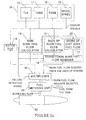
- a turbo-machine 30 receives fuel from a fuel metering unit 20.
- the fuel metering unit 20 is feeded by fuel which comes from the fuel tank of the aircraft.
- the fuel metering unit 20 is either driven by a main burn fuel flow calculator 14 or by a back-up control 25.
- the back-up control 25 provides the burn fuel flow request to the fuel metering unit 20.
- Both the main burn fuel flow calculator 14 and the back-up control 25 collect information coming from a group of sensors 35. The type of information used by the main burn fuel flow calculator 14 and the back-up control 25 will be more detailed in the following description.
- the group of sensors 35 comprises a Throttle Lever Angle ( TLA ) sensor 10, an ambient pressure ( P Amb ) sensor 12, an ambient temperature ( T Amb ) sensor 11 and a turbo-machine speed ( N ) sensor 13.
- a watchdog 16 receives the signals from the group of sensors 35. The watchdog 16 also receives the burn fuel flow request from the main burn fuel flow calculator 14. The watchdog 16 is then able to detect any failure from the main burn fuel flow calculator 14 knowing its inputs and its outputs. In case of a detection of a failure, the main burn fuel flow calculator 14 will inform the back-up control 25 and a multiplexer 19. The multiplexer 19 is responsible for selecting between the burn fuel flow request coming from the back-up system 15 and the burn fuel flow request coming from the main burn fuel flow calculator 14.
- the back-up system 25 comprises a back-up burn fuel flow calculator 15, a storage of the last burn fuel flow 17 and a transitional burn fuel flow manager 18.
- the burn fuel flow calculator 15 may, in one embodiment of the present invention, be identical to the main burn fuel flow calculator 14.
- the purpose of the back-up burn fuel flow calculator 15 is to provide.the amount of fuel that will allow the turbo-machine to adjust his speed in accordance with the TLA 10 chosen by the pilot of the aircraft.
- the last burn fuel flow is stored by the last burn fuel flow storage 17.
- a transitional burn fuel flow manager 18 is enabled in such a case.
- This transitional burn fuel flow manager 18 will provide a burn fuel flow request value that will be equal to a value which is a transition from the last burn fuel flow value which is stored by the last burn fuel flow storage 17 and a value computed by the back-up burn fuel flow calculator 15. This will ensure a smooth transition from the time of failure to the time of recovery by the back-up burn fuel flow calculator 15.
- the back-up control 25 comprises an overspeed control 21.
- the overspeed control 21 receives the spool speed from a group of sensors 35.
- the overspeed control 21 which controls the fuel metering unit 20 imposes a shutdown on the fuel delivery in the turbo-machine 30 via the fuel metering unit 20.
- the group of sensors 35 comprises various identical sensors in order to provide safe information in case of failure of one sensor. Still referring to Fig. 1b, and for a sake of clarity, there is only shown two identical sensors for the spool speed measurement which are the spool speed sensor 13 and the overspeed spool speed sensor 22.
- the back-up burn fuel flow calculator 15 receives also a delayed fuel flow value from a delay unit 26 and a signal from the watchdog unit 16.
- the back-up burn fuel flow calculator 15 also receives its computed burn fuel flow request value using feedback signal 24.
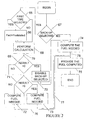
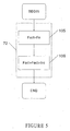
- FIG. 2 there is shown a flowchart which indicates the operations performed by the transitional burn fuel flow manager 18.
- a test is performed by the transitional burn fuel flow manager 18 in order to check if the back-up mode was selected.
- the back-up mode is defined as the period between the failure of the main burn fuel flow calculator 14 and the end of the tracking. If a back-up mode was selected, a test is performed according to step 65 of Fig. 2 to know if this is the first time the back-up mode is selected (i.e. the failure of the main burn fuel flow calculator 14 has just happened). If this is the first time that the back-up mode is selected and according to step 66, the fuel flow request is equal to the latest burn fuel flow request.
- the transitional burn fuel flow manager 18 uses the information stored inside the last burn fuel flow manager to obtain the latest burn fuel flow request.
- step 68 various calculations are then performed.
- step 74 the fuel needed (F N ) is computed.
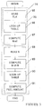
- the computation of the fuel needed (F N ) during step 74 is detailed in Fig. 3.
- This computation is performed by the back-up burn fuel flow calculator 15.
- the TLA signal is read by the back-up burn fuel flow calculator 15.
- An access to a look-up table is done according to step 86.
- step 87 the TLA signal provides a speed reference ( N Ref ) using the access to the look-up table.
- the actual speed of the turbo-machine is read according to step 88 and using the signal coming from the spool speed sensor 13.
- step 90 An access to a look-up table is performed according to step 90.
- the fuel needed is determined using the difference computed and the access to the look-up table.
- the difference between the latest burn fuel flow request ( F Validated ) from the main burn fuel flow calculator 14 and the fuel needed ( F N ) is computed according to step 101.
- a test is performed at step 69 on the result of the difference computed ( F Validated - F N ) 79. If the result is equal to zero, the tracking that ensures a smooth change between the latest burn fuel flow request from the storage 17 and the burn fuel flow request value given by the back-up proportional control loop from the back-up burn fuel flow calculator 15 is finished. According to step 70, the variable that indicates that a back-up mode is selected is disabled. According to step 75, the fuel needed ( F N ) can then be provided to the fuel metering unit 20 via the multiplexer 19.
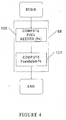
- step 71 a test is performed according to step 71. This test consists in finding out if the result of the difference computed ( F Validated - F N ) 79 is superior to 0. If this is the case, i.e. if the latest fuel flow request is superior than the fuel needed, the amount of fuel to be provided will be computed according to step 73. Now referring to Fig. 6, there is shown the different steps performed during step 73.
- step 110 the spool speed of the turbo-machine ( F N ) is loaded into a single variable ( F Act ).
- step 111 an increment is subtracted from the value ( F Act ) and the new value is stored under the single variable ( F Act ).
- step 105 the spool speed of the turbo-machine ( F N ) is loaded into a single variable ( F Act ). Then, according to step 106, an increment is added to this single variable ( F Act ) and the new value is stored under the single variable ( F Act ).
- the single variable computed ( F Act ) is used to provide the amount of fuel according to step 75.
- the single variable computed ( F Act ) is used to provide the amount of fuel according to step 75.
Landscapes
- Engineering & Computer Science (AREA)
- Chemical & Material Sciences (AREA)
- Combustion & Propulsion (AREA)
- Mechanical Engineering (AREA)
- General Engineering & Computer Science (AREA)
- Electrical Control Of Air Or Fuel Supplied To Internal-Combustion Engine (AREA)
- Output Control And Ontrol Of Special Type Engine (AREA)
- Supercharger (AREA)
- Combined Controls Of Internal Combustion Engines (AREA)
- Control Of Turbines (AREA)
Applications Claiming Priority (2)
| Application Number | Priority Date | Filing Date | Title |
|---|---|---|---|
| US09/742,304 US6568166B2 (en) | 2000-12-22 | 2000-12-22 | Back-up control apparatus for turbo machine |
| EP01271924A EP1343957B1 (de) | 2000-12-22 | 2001-12-13 | Notsteuerungs-verfahren und einrichtung für eine turbomaschine |
Related Parent Applications (1)
| Application Number | Title | Priority Date | Filing Date |
|---|---|---|---|
| EP01271924A Division EP1343957B1 (de) | 2000-12-22 | 2001-12-13 | Notsteuerungs-verfahren und einrichtung für eine turbomaschine |
Publications (3)
| Publication Number | Publication Date |
|---|---|
| EP1852592A2 true EP1852592A2 (de) | 2007-11-07 |
| EP1852592A3 EP1852592A3 (de) | 2007-11-14 |
| EP1852592B1 EP1852592B1 (de) | 2009-02-25 |
Family
ID=24984282
Family Applications (2)
| Application Number | Title | Priority Date | Filing Date |
|---|---|---|---|
| EP07015946A Expired - Lifetime EP1852592B1 (de) | 2000-12-22 | 2001-12-13 | Notsteuerungs-Verfahren für einen Turbomotor |
| EP01271924A Expired - Lifetime EP1343957B1 (de) | 2000-12-22 | 2001-12-13 | Notsteuerungs-verfahren und einrichtung für eine turbomaschine |
Family Applications After (1)
| Application Number | Title | Priority Date | Filing Date |
|---|---|---|---|
| EP01271924A Expired - Lifetime EP1343957B1 (de) | 2000-12-22 | 2001-12-13 | Notsteuerungs-verfahren und einrichtung für eine turbomaschine |
Country Status (5)
| Country | Link |
|---|---|
| US (2) | US6568166B2 (de) |
| EP (2) | EP1852592B1 (de) |
| CA (1) | CA2430660C (de) |
| DE (2) | DE60137806D1 (de) |
| WO (1) | WO2002052135A2 (de) |
Families Citing this family (65)
| Publication number | Priority date | Publication date | Assignee | Title |
|---|---|---|---|---|
| US6929637B2 (en) * | 2002-02-21 | 2005-08-16 | Spiration, Inc. | Device and method for intra-bronchial provision of a therapeutic agent |
| RU2249715C2 (ru) * | 2003-04-04 | 2005-04-10 | Открытое акционерное общество "Техприбор" | Бортовая система контроля авиадвигателя с ограничением температуры, давления и тяги |
| RU2252328C2 (ru) * | 2003-04-04 | 2005-05-20 | Открытое акционерное общество "Техприбор" | Бортовая система контроля авиадвигателя с ограничением частоты вращения, топливных параметров и давления |
| RU2249714C2 (ru) * | 2003-04-04 | 2005-04-10 | Открытое акционерное общество "Техприбор" | Бортовая система контроля авиадвигателя с ограничением давления, топливных параметров и тяги |
| RU2249711C2 (ru) * | 2003-04-04 | 2005-04-10 | Открытое акционерное общество "Техприбор" | Бортовая система контроля авиадвигателя с ограничением частоты вращения, топливных параметров и тяги |
| RU2249717C2 (ru) * | 2003-04-04 | 2005-04-10 | Открытое акционерное общество "Техприбор" | Бортовая система контроля авиадвигателя с ограничением частоты вращения, давления и тяги |
| RU2247843C2 (ru) * | 2003-04-04 | 2005-03-10 | Открытое акционерное общество "Техприбор" | Бортовая система контроля авиадвигателя с ограничением частоты вращения, температуры и давления |
| RU2249712C2 (ru) * | 2003-04-04 | 2005-04-10 | Открытое акционерное общество "Техприбор" | Бортовая система контроля авиадвигателя с ограничением частоты вращения, температуры и тяги |
| RU2250382C2 (ru) * | 2003-04-04 | 2005-04-20 | Открытое акционерное общество "Техприбор" | Бортовая система контроля авиадвигателя с ограничением температуры, топливных параметров и давления |
| RU2249713C2 (ru) * | 2003-04-04 | 2005-04-10 | Открытое акционерное общество "Техприбор" | Бортовая система контроля авиадвигателя с ограничением частоты вращения, температуры и топливных параметров |
| RU2249716C2 (ru) * | 2003-04-04 | 2005-04-10 | Открытое акционерное общество "Техприбор" | Бортовая система контроля авиадвигателя с ограничением температуры, топливных параметров и тяги |
| RU2247845C2 (ru) * | 2003-04-07 | 2005-03-10 | Открытое акционерное общество "Техприбор" | Бортовая система контроля авиадвигателя с ограничением частоты вращения, температуры, топливных параметров и тяги |
| RU2247844C2 (ru) * | 2003-04-07 | 2005-03-10 | Открытое акционерное общество "Техприбор" | Бортовая система контроля авиадвигателя с ограничением частоты вращения, температуры, топливных параметров и давления |
| RU2247846C2 (ru) * | 2003-04-07 | 2005-03-10 | Открытое акционерное общество "Техприбор" | Бортовая система контроля авиадвигателя с ограничением частоты вращения, температуры, давления и тяги |
| RU2247848C2 (ru) * | 2003-04-07 | 2005-03-10 | Открытое акционерное общество "Техприбор" | Бортовая система контроля авиадвигателя с ограничением температуры, топливных параметров, давления и тяги |
| RU2247847C2 (ru) * | 2003-04-07 | 2005-03-10 | Открытое акционерное общество "Техприбор" | Бортовая система контроля авиадвигателя с ограничением частоты вращения, топливных параметров, давления и тяги |
| RU2249119C2 (ru) * | 2003-04-09 | 2005-03-27 | Открытое акционерное общество "Техприбор" | Способ контроля авиадвигателя |
| RU2247849C2 (ru) * | 2003-04-09 | 2005-03-10 | Открытое акционерное общество "Техприбор" | Бортовая система контроля авиадвигателя |
| US7185485B2 (en) * | 2003-05-29 | 2007-03-06 | Honeywell International Inc. | Method and system for failure accommodation of gas generator fuel metering system |
| UA66241C2 (en) * | 2003-09-04 | 2006-01-16 | Vasyl Oleksiiovyc Bezschastnyi | Collected information-measuring system of power unit of an aircraft |
| UA77215C2 (en) * | 2004-05-21 | 2006-11-15 | Vasyl Oleksiiovyc Bezschastnyi | Storage information and measuring system of power unit of flight vehicle |
| US20050274115A1 (en) * | 2004-06-15 | 2005-12-15 | Pearce Kevin P | Method and Apparatus for Prevention of Compressor Stall and Combustion Flameout in a Turbine Engine |
| UA76808C2 (en) * | 2004-06-30 | 2006-09-15 | Vasyl Oleksiiovyc Bezschastnyi | Collecting information-display system of multi-engine power unit of aircraft |
| UA76844C2 (en) * | 2004-10-19 | 2006-09-15 | Vasyl Oleksiiovyc Bezschastnyi | System for control, monitoring and registration of parameters of gas-turbine engine |
| US9097195B2 (en) * | 2004-11-26 | 2015-08-04 | Lysanda Limited | Vehicular diagnostic system |
| US8437903B2 (en) * | 2004-11-26 | 2013-05-07 | Lysanda Limited | Vehicular diagnostic system |
| UA78342C2 (en) * | 2005-02-11 | 2007-03-15 | Vasyl Oleksiiovyc Bezschastnyi | System of control and monitoring of gas-turbine engine parameters |
| US20060217869A1 (en) * | 2005-03-28 | 2006-09-28 | Honeywell International, Inc. | Failsafe electronic engine control system overheat shutdown |
| US7818970B2 (en) | 2005-09-12 | 2010-10-26 | Rolls-Royce Power Engineering Plc | Controlling a gas turbine engine with a transient load |
| RU2313677C1 (ru) * | 2006-04-05 | 2007-12-27 | Открытое акционерное общество "Авиадвигатель" | Способ диагностики двухканальной системы автоматического управления газотурбинного двигателя |
| RU2319026C1 (ru) * | 2006-07-17 | 2008-03-10 | Государственное образовательное учреждение высшего профессионального образования Уфимский государственный авиационный технический университет | Система автоматического регулирования газотурбинного двигателя |
| RU2329388C1 (ru) * | 2006-10-05 | 2008-07-20 | Открытое акционерное общество "СТАР" | Способ защиты газотурбинного двигателя |
| RU2345234C2 (ru) * | 2007-03-15 | 2009-01-27 | Открытое акционерное общество "СТАР" | Способ управления газотурбинным двигателем |
| RU2372505C2 (ru) * | 2007-12-20 | 2009-11-10 | Федеральное государственное унитарное предприятие "Центральный институт авиационного моторостроения имени П.И. Баранова" | Беспроводная отказоустойчивая электронная система управления газотурбинным двигателем |
| RU2378521C2 (ru) * | 2007-12-25 | 2010-01-10 | Федеральное государственное унитарное предприятие "Московское машиностроительное производственное предприятие "САЛЮТ" (ФГУП "ММПП "САЛЮТ") | Система автоматического управления газотурбинным двигателем |
| RU2365775C1 (ru) * | 2008-01-09 | 2009-08-27 | Открытое акционерное общество "КБ Электроприбор" | Система автоматического регулирования параметров газотурбинного двигателя |
| US9355571B2 (en) * | 2008-01-23 | 2016-05-31 | Sikorsky Aircraft Corporation | Modules and methods for biasing power to a multi-engine power plant suitable for one engine inoperative flight procedure training |
| RU2379535C2 (ru) * | 2008-01-28 | 2010-01-20 | Открытое акционерное общество "СТАР" | Способ контроля топливной системы газотурбинного двигателя |
| RU2379534C2 (ru) * | 2008-01-28 | 2010-01-20 | Открытое акционерное общество "СТАР" | Способ управления газотурбинным двигателем |
| RU2387855C2 (ru) * | 2008-05-26 | 2010-04-27 | Открытое акционерное общество "СТАР" | Способ управления газотурбинным двигателем |
| US8099227B2 (en) | 2009-03-19 | 2012-01-17 | Pratt & Whitney Canada Corp. | Control of gas turbine engine |
| US9267443B2 (en) | 2009-05-08 | 2016-02-23 | Gas Turbine Efficiency Sweden Ab | Automated tuning of gas turbine combustion systems |
| US9354618B2 (en) | 2009-05-08 | 2016-05-31 | Gas Turbine Efficiency Sweden Ab | Automated tuning of multiple fuel gas turbine combustion systems |
| US8437941B2 (en) | 2009-05-08 | 2013-05-07 | Gas Turbine Efficiency Sweden Ab | Automated tuning of gas turbine combustion systems |
| US9671797B2 (en) | 2009-05-08 | 2017-06-06 | Gas Turbine Efficiency Sweden Ab | Optimization of gas turbine combustion systems low load performance on simple cycle and heat recovery steam generator applications |
| RU2412366C1 (ru) * | 2009-07-13 | 2011-02-20 | Учреждение Российской академии наук Институт механики Уфимского научного центра РАН | Система автоматического регулирования газотурбинного двигателя |
| FR2950324B1 (fr) * | 2009-09-23 | 2011-08-26 | Eurocopter France | Procede et dispositif d'aide au pilotage d'un aeronef en cas de pannes d'un indicateur de premiere limitation |
| US8805593B2 (en) * | 2009-11-18 | 2014-08-12 | Energy Control Technologies, Inc. | Fault tolerant analog outputs for turbo compressors |
| RU2425255C1 (ru) * | 2010-02-19 | 2011-07-27 | Федеральное государственное унитарное предприятие "Научно-производственный центр газотурбостроения "Салют" (ФГУП "НПЦ газотурбостроения "Салют") | Способ управления положением направляющих аппаратов компрессора газотурбинного двигателя |
| RU2432501C1 (ru) * | 2010-04-16 | 2011-10-27 | Федеральное государственное унитарное предприятие "Научно-производственный центр газотурбостроения "Салют"(ФГУП "НПЦ газотурбостроения "Салют") | Способ управления положением направляющих аппаратов компрессора газотурбинного двигателя |
| RU2454557C2 (ru) * | 2010-09-22 | 2012-06-27 | Закрытое Акционерное Общество Научно-Производственная Фирма "Газ-Система-Сервис" | Способ управления газотурбинной установкой |
| RU2445483C1 (ru) * | 2010-11-29 | 2012-03-20 | Федеральное государственное унитарное предприятие "Научно-производственный центр газотурбостроения "Салют" (ФГУП "НПЦ газотурбостроения "Салют") | Способ восстановления информации измерительного канала газотурбинного двигателя |
| RU2474713C2 (ru) * | 2010-12-29 | 2013-02-10 | Открытое акционерное общество "СТАР" | Способ защиты газотурбинного двигателя |
| GB201105830D0 (en) | 2011-04-06 | 2011-05-18 | Lysanda Ltd | Mass estimation model |
| RU2490492C1 (ru) * | 2012-02-07 | 2013-08-20 | Открытое акционерное общество "Научно-производственное объединение "Сатурн" (ОАО "НПО "Сатурн") | Способ управления газотурбинным двигателем и система для его осуществления |
| RU2501964C1 (ru) * | 2012-04-27 | 2013-12-20 | Открытое акционерное общество "Концерн Кизлярский электромеханический завод" (ОАО "Концерн КЭМЗ") | Система управления газотурбинным двигателем |
| RU2592360C2 (ru) * | 2014-11-27 | 2016-07-20 | Открытое акционерное общество "Уфимское моторостроительное производственное объединение" ОАО УМПО | Способ регулирования авиационного турбореактивного двигателя |
| RU2601712C2 (ru) * | 2015-03-06 | 2016-11-10 | Акционерное общество "Уфимское научно-производственное предприятие "Молния" | Помехоустойчивый самонастраивающийся измеритель температуры газа газотурбинного двигателя |
| RU2602705C1 (ru) * | 2015-05-07 | 2016-11-20 | Федеральное государственное казенное военное образовательное учреждение высшего профессионального образования "Военный учебно-научный центр Военно-воздушных сил "Военно-воздушная академия имени профессора Н.Е. Жуковского и Ю.А. Гагарина" (г. Воронеж) Министерства обороны Российской Федерации | Способ управления основной камерой сгорания газотурбинного двигателя |
| US11053861B2 (en) | 2016-03-03 | 2021-07-06 | General Electric Company | Overspeed protection system and method |
| RU2627627C1 (ru) * | 2016-08-09 | 2017-08-09 | Публичное акционерное общество "Уфимское моторостроительное производственное объединение" ПАО "УМПО" | Способ регулирования авиационного турбореактивного двухконтурного двигателя |
| RU2637801C1 (ru) * | 2017-02-15 | 2017-12-07 | федеральное государственное автономное образовательное учреждение высшего образования "Санкт-Петербургский политехнический университет Петра Великого" (ФГАОУ ВО "СПбПУ") | Беспроводная электронная система контроля и диагностики авиационного газотурбинного двигателя |
| RU2661802C1 (ru) * | 2017-04-19 | 2018-07-19 | Акционерное общество "Омское машиностроительное конструкторское бюро" | Способ контроля системы управления газотурбинным двигателем |
| US11440677B2 (en) * | 2018-11-16 | 2022-09-13 | Rolls-Royce Corporation | Secured backup feature for an embedded system |
| FR3130757B1 (fr) * | 2021-12-17 | 2023-12-22 | Safran Helicopter Engines | Procédé de régulation de la vitesse de rotation d’un propulseur d’un groupe propulsif hybride pour aéronef, en situation de panne du système de régulation principal du moteur thermique du groupe propulsif hybride |
Family Cites Families (19)
| Publication number | Priority date | Publication date | Assignee | Title |
|---|---|---|---|---|
| US3811273A (en) | 1973-03-08 | 1974-05-21 | United Aircraft Corp | Slaved fuel control for multi-engined aircraft |
| US3975902A (en) | 1974-06-04 | 1976-08-24 | Westinghouse Electric Corp. | Local maintenance controller for gas turbine power plants having a primary control system |
| US3978659A (en) * | 1975-02-19 | 1976-09-07 | Westinghouse Electric Corporation | Bumpless transfer in shifting control command between the primary and backup control systems of a gas turbine power plant |
| US4134257A (en) | 1976-11-03 | 1979-01-16 | The Garrett Corporation | Gas turbine fuel delivery and control system |
| GB1597129A (en) | 1976-12-20 | 1981-09-03 | Gen Electric | Gas turbine engine control system |
| US4248040A (en) * | 1979-06-04 | 1981-02-03 | General Electric Company | Integrated control system for a gas turbine engine |
| GB2052805B (en) | 1979-06-29 | 1983-03-09 | Smiths Industries Ltd | Gas-turbine engine control |
| US4429528A (en) | 1980-01-22 | 1984-02-07 | Plessey Overseas Limited | Emergency fuel system |
| US4397148A (en) * | 1980-07-02 | 1983-08-09 | General Electric Company | Control system for an augmented turbofan engine |
| GB8517744D0 (en) | 1985-07-12 | 1995-11-08 | Rolls Royce | Fuel control system |
| US4821193A (en) | 1985-08-26 | 1989-04-11 | General Electric Company | Digital control for gas turbine engine |
| US4712372A (en) | 1985-09-18 | 1987-12-15 | Avco Corporation | Overspeed system redundancy monitor |
| GB8526726D0 (en) | 1985-10-30 | 1985-12-04 | Rolls Royce | Failsafe electronic control system |
| US4794755A (en) | 1987-05-14 | 1989-01-03 | The United States Of America As Represented By The Secretary Of The Air Force | Back-up control system for F101 engine and its derivatives |
| US4837697A (en) | 1987-07-31 | 1989-06-06 | Allied-Signal Inc. | Overspeed governor for an electronic controlled fuel system |
| GB8800904D0 (en) | 1988-01-15 | 1988-02-17 | Rolls Royce Plc | Fuel control system |
| US5363317A (en) | 1992-10-29 | 1994-11-08 | United Technologies Corporation | Engine failure monitor for a multi-engine aircraft having partial engine failure and driveshaft failure detection |
| GB2272783B (en) | 1992-11-20 | 1996-05-22 | Rolls Royce Plc | Aircraft engine control system |
| US5394689A (en) | 1993-09-22 | 1995-03-07 | General Electric Company | Gas turbine engine control system having integral flight Mach number synthesis method |
-
2000
- 2000-12-22 US US09/742,304 patent/US6568166B2/en not_active Expired - Lifetime
-
2001
- 2001-12-13 CA CA2430660A patent/CA2430660C/en not_active Expired - Fee Related
- 2001-12-13 EP EP07015946A patent/EP1852592B1/de not_active Expired - Lifetime
- 2001-12-13 DE DE60137806T patent/DE60137806D1/de not_active Expired - Lifetime
- 2001-12-13 WO PCT/CA2001/001778 patent/WO2002052135A2/en not_active Ceased
- 2001-12-13 DE DE60130579T patent/DE60130579T2/de not_active Expired - Lifetime
- 2001-12-13 EP EP01271924A patent/EP1343957B1/de not_active Expired - Lifetime
-
2002
- 2002-12-13 US US10/318,219 patent/US6745572B2/en not_active Expired - Lifetime
Also Published As
| Publication number | Publication date |
|---|---|
| CA2430660C (en) | 2011-07-26 |
| EP1343957B1 (de) | 2007-09-19 |
| EP1343957A2 (de) | 2003-09-17 |
| US20030079476A1 (en) | 2003-05-01 |
| CA2430660A1 (en) | 2002-07-04 |
| US20020078692A1 (en) | 2002-06-27 |
| DE60130579T2 (de) | 2008-06-12 |
| US6568166B2 (en) | 2003-05-27 |
| WO2002052135A3 (en) | 2002-10-03 |
| WO2002052135A2 (en) | 2002-07-04 |
| DE60137806D1 (de) | 2009-04-09 |
| US6745572B2 (en) | 2004-06-08 |
| EP1852592A3 (de) | 2007-11-14 |
| DE60130579D1 (de) | 2007-10-31 |
| EP1852592B1 (de) | 2009-02-25 |
Similar Documents
| Publication | Publication Date | Title |
|---|---|---|
| EP1852592B1 (de) | Notsteuerungs-Verfahren für einen Turbomotor | |
| US9494085B2 (en) | System and method for load power management in a turboshaft gas turbine engine | |
| JP5550552B2 (ja) | コンプレッサにアクティブ安定化を施すようにしたガスタービンの制御 | |
| US12140083B2 (en) | Adaptive model predictive control for hybrid electric propulsion | |
| US5279107A (en) | Fuel control system with fuel metering valve fault accommodation | |
| US6098011A (en) | Efficient fuzzy logic fault accommodation algorithm | |
| US5775090A (en) | Torque signal synthesis method and system for a gas turbine engine | |
| EP4035998B1 (de) | System und verfahren zur fehlererkennung einer propellerrückkopplungsvorrichtung | |
| US20260063075A1 (en) | Hybrid electric idle and braking for an aircraft | |
| EP4019396B1 (de) | System und verfahren zur erkennung von propellerfehlfunktionen | |
| EP1312781B1 (de) | Verfahren zur Detektion der im Wertebereich bleibenden Sensorfehler eines Motors | |
| US11519340B2 (en) | System and method for controlling a speed of rotation of an aircraft turbine engine with fault management | |
| US4765133A (en) | Fuel control with smooth mode transition | |
| US5967758A (en) | Controlling device for controlling rotational speed of engine of hydraulic working machine | |
| CN113678107A (zh) | 冗余采集系统中的故障定位 | |
| JPS63150434A (ja) | ガスタービンエンジンの制御装置及び方法 | |
| US11891919B2 (en) | Automatic blade pitch control | |
| EP0668552A1 (de) | Steuergerät | |
| EP4421574B1 (de) | Gasturbinenmotorsteuerungssystem | |
| US12448113B2 (en) | Protection system | |
| JPS59131786A (ja) | 油圧ポンプの故障診断装置 | |
| US12006877B2 (en) | Method and system for controlling a turbomachine with control saturations management | |
| US20230159180A1 (en) | Method for managing the amounts of power drawn from power units of the propulsion units of an aircraft | |
| CN118407927A (zh) | 空压机反转识别方法及装置 |
Legal Events
| Date | Code | Title | Description |
|---|---|---|---|
| PUAI | Public reference made under article 153(3) epc to a published international application that has entered the european phase |
Free format text: ORIGINAL CODE: 0009012 |
|
| PUAL | Search report despatched |
Free format text: ORIGINAL CODE: 0009013 |
|
| AC | Divisional application: reference to earlier application |
Ref document number: 1343957 Country of ref document: EP Kind code of ref document: P |
|
| AK | Designated contracting states |
Kind code of ref document: A2 Designated state(s): DE FR GB |
|
| AK | Designated contracting states |
Kind code of ref document: A3 Designated state(s): DE FR GB |
|
| RIN1 | Information on inventor provided before grant (corrected) |
Inventor name: GRATTON, DANIEL C. Inventor name: JAY, ALEXANDRE Inventor name: JARVO, JIM R. |
|
| 17P | Request for examination filed |
Effective date: 20080124 |
|
| 17Q | First examination report despatched |
Effective date: 20080229 |
|
| AKX | Designation fees paid |
Designated state(s): DE FR GB |
|
| GRAP | Despatch of communication of intention to grant a patent |
Free format text: ORIGINAL CODE: EPIDOSNIGR1 |
|
| GRAS | Grant fee paid |
Free format text: ORIGINAL CODE: EPIDOSNIGR3 |
|
| GRAA | (expected) grant |
Free format text: ORIGINAL CODE: 0009210 |
|
| AC | Divisional application: reference to earlier application |
Ref document number: 1343957 Country of ref document: EP Kind code of ref document: P |
|
| AK | Designated contracting states |
Kind code of ref document: B1 Designated state(s): DE FR GB |
|
| REG | Reference to a national code |
Ref country code: GB Ref legal event code: FG4D |
|
| REF | Corresponds to: |
Ref document number: 60137806 Country of ref document: DE Date of ref document: 20090409 Kind code of ref document: P |
|
| PLBE | No opposition filed within time limit |
Free format text: ORIGINAL CODE: 0009261 |
|
| STAA | Information on the status of an ep patent application or granted ep patent |
Free format text: STATUS: NO OPPOSITION FILED WITHIN TIME LIMIT |
|
| 26N | No opposition filed |
Effective date: 20091126 |
|
| PGFP | Annual fee paid to national office [announced via postgrant information from national office to epo] |
Ref country code: DE Payment date: 20101215 Year of fee payment: 10 |
|
| REG | Reference to a national code |
Ref country code: DE Ref legal event code: R119 Ref document number: 60137806 Country of ref document: DE Effective date: 20130702 |
|
| PG25 | Lapsed in a contracting state [announced via postgrant information from national office to epo] |
Ref country code: DE Free format text: LAPSE BECAUSE OF NON-PAYMENT OF DUE FEES Effective date: 20130702 |
|
| REG | Reference to a national code |
Ref country code: FR Ref legal event code: PLFP Year of fee payment: 15 |
|
| REG | Reference to a national code |
Ref country code: FR Ref legal event code: PLFP Year of fee payment: 16 |
|
| REG | Reference to a national code |
Ref country code: FR Ref legal event code: PLFP Year of fee payment: 17 |
|
| PGFP | Annual fee paid to national office [announced via postgrant information from national office to epo] |
Ref country code: GB Payment date: 20181127 Year of fee payment: 18 Ref country code: FR Payment date: 20181127 Year of fee payment: 18 |
|
| GBPC | Gb: european patent ceased through non-payment of renewal fee |
Effective date: 20191213 |
|
| PG25 | Lapsed in a contracting state [announced via postgrant information from national office to epo] |
Ref country code: GB Free format text: LAPSE BECAUSE OF NON-PAYMENT OF DUE FEES Effective date: 20191213 Ref country code: FR Free format text: LAPSE BECAUSE OF NON-PAYMENT OF DUE FEES Effective date: 20191231 |