EP1857230A1 - Structure d'articulation de robot - Google Patents
Structure d'articulation de robot Download PDFInfo
- Publication number
- EP1857230A1 EP1857230A1 EP07707156A EP07707156A EP1857230A1 EP 1857230 A1 EP1857230 A1 EP 1857230A1 EP 07707156 A EP07707156 A EP 07707156A EP 07707156 A EP07707156 A EP 07707156A EP 1857230 A1 EP1857230 A1 EP 1857230A1
- Authority
- EP
- European Patent Office
- Prior art keywords
- link
- shaft
- coupled
- rod
- lateral
- Prior art date
- Legal status (The legal status is an assumption and is not a legal conclusion. Google has not performed a legal analysis and makes no representation as to the accuracy of the status listed.)
- Granted
Links
Images



Classifications
-
- B—PERFORMING OPERATIONS; TRANSPORTING
- B25—HAND TOOLS; PORTABLE POWER-DRIVEN TOOLS; MANIPULATORS
- B25J—MANIPULATORS; CHAMBERS PROVIDED WITH MANIPULATION DEVICES
- B25J17/00—Joints
- B25J17/02—Wrist joints
-
- B—PERFORMING OPERATIONS; TRANSPORTING
- B25—HAND TOOLS; PORTABLE POWER-DRIVEN TOOLS; MANIPULATORS
- B25J—MANIPULATORS; CHAMBERS PROVIDED WITH MANIPULATION DEVICES
- B25J17/00—Joints
- B25J17/02—Wrist joints
- B25J17/0258—Two-dimensional joints
-
- B—PERFORMING OPERATIONS; TRANSPORTING
- B25—HAND TOOLS; PORTABLE POWER-DRIVEN TOOLS; MANIPULATORS
- B25J—MANIPULATORS; CHAMBERS PROVIDED WITH MANIPULATION DEVICES
- B25J15/00—Gripping heads and other end effectors
- B25J15/0009—Gripping heads and other end effectors comprising multi-articulated fingers, e.g. resembling a human hand
-
- B—PERFORMING OPERATIONS; TRANSPORTING
- B25—HAND TOOLS; PORTABLE POWER-DRIVEN TOOLS; MANIPULATORS
- B25J—MANIPULATORS; CHAMBERS PROVIDED WITH MANIPULATION DEVICES
- B25J17/00—Joints
- B25J17/02—Wrist joints
- B25J17/0258—Two-dimensional joints
- B25J17/0266—Two-dimensional joints comprising more than two actuating or connecting rods
-
- B—PERFORMING OPERATIONS; TRANSPORTING
- B25—HAND TOOLS; PORTABLE POWER-DRIVEN TOOLS; MANIPULATORS
- B25J—MANIPULATORS; CHAMBERS PROVIDED WITH MANIPULATION DEVICES
- B25J17/00—Joints
- B25J17/02—Wrist joints
- B25J17/0258—Two-dimensional joints
- B25J17/0275—Universal joints, e.g. Hooke, Cardan, ball joints
-
- B—PERFORMING OPERATIONS; TRANSPORTING
- B25—HAND TOOLS; PORTABLE POWER-DRIVEN TOOLS; MANIPULATORS
- B25J—MANIPULATORS; CHAMBERS PROVIDED WITH MANIPULATION DEVICES
- B25J9/00—Program-controlled manipulators
- B25J9/003—Program-controlled manipulators having parallel kinematics
- B25J9/0045—Program-controlled manipulators having parallel kinematics with kinematics chains having a rotary joint at the base
- B25J9/0048—Program-controlled manipulators having parallel kinematics with kinematics chains having a rotary joint at the base with kinematics chains of the type rotary-rotary-rotary
-
- Y—GENERAL TAGGING OF NEW TECHNOLOGICAL DEVELOPMENTS; GENERAL TAGGING OF CROSS-SECTIONAL TECHNOLOGIES SPANNING OVER SEVERAL SECTIONS OF THE IPC; TECHNICAL SUBJECTS COVERED BY FORMER USPC CROSS-REFERENCE ART COLLECTIONS [XRACs] AND DIGESTS
- Y10—TECHNICAL SUBJECTS COVERED BY FORMER USPC
- Y10T—TECHNICAL SUBJECTS COVERED BY FORMER US CLASSIFICATION
- Y10T74/00—Machine element or mechanism
- Y10T74/20—Control lever and linkage systems
- Y10T74/20207—Multiple controlling elements for single controlled element
- Y10T74/20305—Robotic arm
- Y10T74/20329—Joint between elements
Definitions
- the present invention relates to a joint structure of a robot, more specifically, to a joint structure thereof having a wide movable range.
- a joint structure of a wrist of a robot which includes a motor, a feed screw mechanism, or the like to achieve a longitudinal swing motion and a lateral swing motion.
- Japanese Laid-Open Patent Application, Publication No. 2003-170381 discloses a joint structure of a wrist of a humanoid robot.
- a feed screw converts a rotational motion of a motor into a linear motion; and a moving block which operates in the linear motion is coupled to a hand via a universal joint, to thereby enable the longitudinal swing motion or lateral swing motion of the wrist.
- the feed screw mechanism disclosed in Japanese Laid-Open Patent Application, Publication No. 2003-170381 has such problems as follows. If motion angles of the longitudinal swing motion and the lateral swing motion of an arm are set wider, a stroke of the feed screw as well as a length of the arm itself have to be longer. This restricts designing of the arm. A burden applied to the motor is also increased due to an increase in inertia moment of the arm. Further, because the feed screw receives a load applied to the mechanism, there is concern about its load resistance for use in the joint structure of a robot.
- Another problem is that, if the motion angles are set wider, because a rotational angle of a link itself of the joint inevitably becomes larger, the link of the joint, or a cover or the like interlocking with the link interferes with internal components in the link, such as a motor. This results in obstruction of motions of the joint.
- an aspect of the present invention is to provide a compact joint structure of a robot, while a wide movable angle of a joint thereof is ensured.
- an aspect of the present invention relates to a joint structure of a robot for performing a longitudinal swing motion and a lateral swing motion of a coupled body, using a drive mechanism, with respect to a robot link for use in the joint structure of the robot.
- the joint structure includes: a base link as a main body of the robot link having a pair of facing portions; a gimbal link having first and second rotational shafts which are not parallel to each other so as to provide the longitudinal swing motion and lateral swing motion of the coupled body, the first rotational shaft being supported between the pair of facing portions; a main link with one end thereof coupled to the second rotational shaft of the gimbal link and with the other end thereof coupled to the coupled body; and a sub link with one end thereof coupled to the gimbal link and with the other end thereof coupled to the coupled body, the sub link being provided crosswise with the main link to form a four link mechanism therewith.
- a coupled body used herein means a coupled member such as a hand and an arm, which is coupled to the robot link via a joint.
- the coupled body includes not only a terminal member coupled to a link but also an intermediate member such as a link itself.
- the expression “two rotational shafts not parallel to each other” used herein means that the two rotational shaft intersect with each other in the same plane, or intersect not in the same plane but do so when viewed from above.
- the robot link and the gimbal link are rotatably coupled by the first rotational shaft; the gimbal link and the coupled body are rotatably coupled by the second rotational shaft; and the first rotational shaft and the second rotational shaft are provided not being parallel to each other.
- a rotational motion about the first rotational shaft and that about the second rotational shaft are combined, so that the longitudinal swing motion and the lateral swing motion of the coupled body can be freely performed with respect to the robot link.
- the gimbal link and the coupled body are coupled with the four link mechanism, in which the main link and the sub link are provided crosswise.
- the coupled body in the rotational direction of the gimbal link about the second rotational shaft, the coupled body during its swing motion in a certain direction is swung to tilt further in the direction.
- a swing angle (a tilt angle) of the coupled body is larger than the rotational angle of the main link. Even with a smaller rotation of the main link, the coupled body swings (tilts) to a larger extent.
- the rotational angle of the main link is therefore minimized, and interference between the main link in a rotational motion and the internal components is prevented.
- a compact joint structure of a robot is realized, while a large swing angle of the coupled body is ensured.
- a swing speed of the coupled body is increased in the direction, to thereby tilt further in the direction.
- the joint structure hence moves and responds quickly.
- the first rotational shaft may be configured to be a longitudinal shaft serving as a rotational shaft for the lateral swing motion of the coupled body.
- the second rotational shaft may be configured to be a lateral shaft serving as a rotational shaft for the longitudinal swing motion of the coupled body.
- the lateral shaft is herein provided in a direction orthogonal to the longitudinal shaft.
- the longitudinal shaft which is the first rotational shaft
- the lateral shaft which is the second rotational shaft
- the robot may be a humanoid robot.
- the robot link may be a link of an arm of the humanoid robot.
- the arm is between its elbow and its wrist.
- the coupled body may be a hand of the robot.
- the hand is between its wrist and its finger tips.
- a swing direction of the longitudinal swing motion may be directions in which a palm of the hand and a back of the hand are faced.
- the swing direction of the longitudinal swing motion is the directions in which the palm of the hand and the back of the hand are faced. This enables a larger swing angle of the longitudinal swing motion of the robot.
- a human wrist also has a larger swing angle in a direction of the longitudinal swing motion than in a direction of the lateral swing motion. Thus, such a motion of the wrist of the robot more looks like that of a human.
- the swing angle of the hand is larger than the rotational angle of the main link. This means that, even with a smaller rotation of the main link, the hand swings to a greater extent. Therefore, interference between the main link during its rotational motion and the internal components is prevented, and a compact joint structure of the wrist is realized, while ensuring a large swing angle of the coupled body.
- the main link may be longer than the sub link.
- the hand is coupled to the arm link, such that the main link is fixed to a palm side of the hand, and the sub link is fixed to a back side of the hand.
- a length of the main link is different from that of the sub link. Therefore, interference between the two links is prevented, while ensuring a large rotational angle of the links.
- a swing angle of the hand is larger on the palm side of the hand than on the back side thereof. This allows a quick motion of the hand.
- a compact and more-human-like joint structure of the wrist can also be realized.
- the main link in the present invention may have a configuration as follows.
- the main link spans both sides of the longitudinal shaft.
- a first rod and a second rod for pivoting the main link in a direction for the longitudinal swing motion and in a direction for the lateral swing motion are coupled to the main link via respective adjustable joints.
- the first rod is coupled to the main link in a different position from the lateral shaft, and, on one side of the longitudinal shaft, in a different position from the longitudinal shaft.
- the second rod is coupled to the main link in the different position from the lateral shaft, and, on the other side of the longitudinal shaft, in the different position from the longitudinal shaft.
- the main link in the present invention may have another configuration as follows.
- the main link spans both sides of the lateral shaft.
- the first rod and the second rod for pivoting the main link in the longitudinal swing motion direction and in the lateral swing motion direction are coupled to the main link via respective adjustable joints.
- the first rod is coupled to the main link in a different position from the longitudinal shaft, and, on one side of the lateral shaft, in a different position from the lateral shaft.
- the second rod is coupled to the main link in the different position from the longitudinal shaft, and, on the other side of the lateral shaft, in the different position from the lateral shaft.
- the first rod and the second rod are coupled via the adjustable joints to the main link in the different positions from the longitudinal shaft and the lateral shaft, respectively.
- the main link can be rotated about the longitudinal shaft and the lateral shaft, when the first rod and the second rod are moved forward or backward.
- the longitudinal swing motion and the lateral swing motion are performed in a balanced and smooth way.
- a line is assumed to connect between a first coupling point, at which the first rod is coupled to the main link, and a second coupling point, at which the second rod is coupled to the main link.
- the line connecting the two points is preferably parallel to the longitudinal shaft or the lateral shaft.
- the first coupling point and the second coupling point are preferably at equal distances from the longitudinal shaft and the lateral shaft, respectively.
- the first rod and the second rod are parallel to each other with respect to the longitudinal shaft or the lateral shaft, and the first coupling point and the second coupling point are at equal distances from the longitudinal shaft and the lateral shaft, respectively.
- the main link can be rotated about the longitudinal shaft or the lateral shaft, by moving forward or backward the first rod and the second rod by the same distances, or by moving forward any one of the first rod and the second rod by a predetermined distance, and moving the other backward by the same distance.
- the motions in the longitudinal swing direction and the lateral swing motion direction can be performed by coordinating and synchronizing the first rod and the second rod. This ensures smooth and easily controllable motions.
- the gimbal link may have a configuration as follows.
- a longitudinal shaft portion serving as the longitudinal shaft and a lateral shaft portion serving as the lateral shaft are provided in a cross shape.
- a ring portion is provided with a through hole in a middle portion in the cross shape. The longitudinal shaft portion and the lateral shaft portion protrude each to the outside of the ring portion.
- the gimbal link has the through hole in the middle portion in the cross shape. This allows a harness, hydraulic and pneumatic piping, or the like to run through the center of the robot link.
- the harness or the like does not obstruct motions of the joint, thus ensuring a wide movable angle of the joint. Further, an excessive load applied on the harness can be prevented, thus avoiding possible disconnection of the harness.
- the first rod may be coupled to a first motor included in the drive mechanism via an adjustable joint
- a second rod may be coupled to a second motor also included in the drive mechanism via another adjustable joint
- the two motors are coordinatedly operated so as to perform the longitudinal swing motion and the lateral swing motion. This allows the motors to be downsized, and the robot link to be made more compact. Further, the adjustable joints have aligning functions to smoothly convert a linear motion into a rotational motion.
- the present invention relates to a joint structure of a wrist of a humanoid robot, which performs a longitudinal swing motion and a lateral swing motion of a hand between a wrist and finger tips of the robot, using a drive mechanism, with respect to an arm link between an elbow and the wrist.
- the joint structure includes: a base link as a main body of the arm link having a pair of facing portions; a gimbal link having a longitudinal shaft serving as a rotational shaft for the lateral swing motion of the hand, and a lateral shaft serving as a rotational shaft for the longitudinal swing motion thereof, the longitudinal shaft being supported between the pair of facing portions; a main link with one end thereof coupled to the lateral shaft of the gimbal link and with the other end thereof coupled to the hand, the main link pivoting about the lateral shaft in a direction for the longitudinal swing motion; and a sub link with one end thereof coupled to the gimbal link and with the other end thereof coupled to the hand, the sub link being provided crosswise with the main link to form a four link mechanism therewith.
- a first rod and the second rod for pivoting the main link in the longitudinal swing motion direction and in the lateral swing motion direction are coupled to the main link via respective adjustable joints.
- One end of the first rod is coupled to the main link in a different position from the lateral shaft, and, on one side of the longitudinal shaft, in a different position from the longitudinal shaft.
- the other end of the first rod is coupled to a first motor included in the drive mechanism, via an adjustable joint.
- One end of the second rod is coupled to the main link in the different position from the lateral shaft, and, on the other side of the longitudinal shaft, in the different position from the longitudinal shaft.
- the other end of the second rod is coupled to a second motor included in the drive mechanism, via an adjustable joint.
- a line connecting a first coupling point, at which the first rod is coupled to the main link, and a second coupling point, at which the second rod is coupled to the main link, are parallel to the longitudinal shaft or the lateral shaft. And, at the same time, the first coupling point and the second coupling point are at equal distances from the longitudinal shaft and the lateral shaft, respectively.
- the hand is coupled to the arm link, such that a plane formed by the palm of the hand is substantially parallel to a plane formed by the first rod and the second rod, in a position where the hand is straight to the arm link.
- the hand is coupled to the arm link, such that the plane formed by the palm is parallel to the plane formed by the first rod and the second rod. This facilitates a correspondence between a travel distance of each of the rods and a position of the hand, thus making a control over the motions of the hand easier.
- the joint structure of a robot according to the present invention is assumed to be a joint structure of a wrist of a humanoid robot.
- the present invention is not limited to this.
- the present invention may be applied to an ankle joint of a humanoid robot, a connecting part of a link of an industrial robot, or the like.
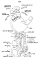
- the joint structure of the wrist of the humanoid robot includes, as shown in FIG. 1, an arm link 2 which is a robot link; a wrist joint 3 coupled to the arm link 2; a hand 8 which is a coupled body coupled to the wrist joint 3; and a drive mechanism 9 for performing longitudinal and lateral swing motions of the hand 8.
- the joint structure is configured such that facing portions 21a,21a formed in the arm link 2 support a longitudinal shaft portion 41 of a gimbal link 4.
- the gimbal link 4 is freely rotatable in a direction for the lateral swing motion.
- the main link 5 is pivotably coupled to a lateral shaft part 42 of the gimbal link 4, and the sub link 6 is coupled to a secondary shaft 45 of the gimbal link 4.
- the main link 5 and the sub link 6 are freely rotatable in a direction for the longitudinal swing motion.
- the hand 8 coupled to the main link 5 and the sub link 6 are freely swingable both in the longitudinal swing motion direction and in the lateral swing motion direction (see also FIG. 3).
- the arm link 2 includes a base link 21 as a base of the arm link 2, and a drive mechanism 9 attached to the base link 21.
- the pair of facing portions 21a,21a for rotatably supporting the longitudinal shaft portion 41 of the gimbal link 4 are formed in the base link 21.
- a configuration concerning motions of the joint structure of the wrist is described, and components other than those concerning the motions, such as a control mechanism, a sensor, a harness, or the like are not shown.
- the drive mechanism 9 includes a first motor 91 and a second motor 92 each as a driving source; harmonic reducers 93,94 respectively connected to the first motor 91 and the second motor 92 via respective driving belts not shown; output arms 95, 96 coupled to respective output axes of the harmonic reducers 93,94; a first rod 71 and a second rod 72, one ends of which are coupled to the output arms 95, 96 respectively via spherical joints 95a,96a, and the other ends of which are coupled to the main link 5 via respective universal joints 71a,72a.
- the spherical joints 95a,96a are adjustable joints having aligning functions.
- the universal joints 71a,72a are also adjustable joints.
- a rotary drive by the motor is used.
- the present invention is not limited to this, and a linear drive by a hydraulic cylinder or a ball screw may be used.
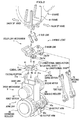
- the wrist joint 3 includes, as shown in FIG. 3, the gimbal link 4 rotatably supported by the facing portions 21a, 21a of the arm link 2; the main link 5 coupled to the lateral shaft part 42 of the gimbal link 4; and the sub link 6 provided crosswise with the main link 5.
- the gimbal link 4 includes a rectangle ring part 44 provided in a middle thereof; and the longitudinal shaft portion 41 and the lateral shaft part 42, which are provided crosswise with each other and protrude from respective sides of the ring part 44.
- the ring part 44 has a rectangle ring shape having a through hole 43 therein, and is provided in the middle of the gimbal link 4.
- the longitudinal shaft portion 41 and the lateral shaft part 42 are provided protruding from the respective opposite sides of the ring part 44 to the outside.
- the longitudinal shaft portion 41 of the gimbal link 4 operates as a longitudinal shaft 4a of a rotational shaft for the lateral swing motion of the hand 8.
- the lateral shaft part 42 of the gimbal link 4 operates as a lateral shaft 4b of a rotational shaft for the longitudinal swing motion.
- both ends of the longitudinal shaft portion 41 are rotatably supported by the facing portions 21a,21a of the base link 21, so that the gimbal link 4 can rotate in a direction for the lateral swing motion.
- the through hole 43 is provided in the middle of the gimbal link 4, a harness, a hydraulic or pneumatic pipe, or the like may run through the through hole 43. Therefore, when the gimbal link 4 is rotated, the harness or the like hardly obstruct motions of the gimbal link 4, thus ensuring a wide movable angle of the joint. Further, an excessive load applied to the harness can be prevented, thus avoiding possible disconnection of the harness.
- the secondary shaft 45 is provided in the longitudinal shaft portion 41 of the gimbal link 4, and is provided parallel to the lateral shaft part 42.
- the sub link 6 to be described later is rotatably coupled to the secondary shaft 45 in a rotational direction for the longitudinal swing motion.
- the gimbal link 4 is configured to have a cross shape with a through hole in the middle thereof.
- the gimbal link 4 may have a disk or any other shape, as long as the gimbal link 4 has the longitudinal shaft 4a as the rotational shaft for the lateral swing motion and the lateral shaft 4b as the rotational shaft for the longitudinal swing motion.
- the main link 5 is, as shown in FIG. 3, configured to be a rectangle frame member having a large through hole in the middle thereof, when viewed from above.
- the main link 5 includes an integral combination of a pair of main link bodies 51a,51b, which are opposing to each other and each have a triangle shaped face when viewed from a lateral side thereof; and a pair of connecting parts 52,53.
- the sub link 6 to be described later is coupled to the secondary shaft 45 of the gimbal link 4 inside the frame-shaped main link 5.
- the main link 5 ensures a span for supporting the hand 8 in a direction of the lateral shaft 4b.
- the main link 5 stably holds the hand 8 coupled thereto, while the main link 5 receives the sub link 6 inside thereof in a balanced manner.
- a first link 5a and a second link 5b (see FIG. 4) forming a four link mechanism 1 are provided adjacent to one sides of the respective triangle shaped faces of the main link bodies 51a,51b.
- the first link 5a is a part for coupling one end of the main link 5 and the lateral shaft part 42 of the gimbal link 4.
- the second link 5b is a part for coupling the other end of the main link 5 and a main link coupling hole 8a, which is formed in a frame 81 of the hand 8.
- a length between the first link 5a and the second link 5b is referred to as a link length ⁇ 1 of the main link 5 (see FIG. 4).
- first rod 71 and the second rod 72 are coupled adjacent to the other two sides of the respective triangle-shaped faces of the main link bodies 51a,51b via universal joints 71a,72a.
- the universal joints 71a,72a are the adjustable joints having aligning functions.
- a position where the first rod 71 is coupled to the main link body 51a is a first coupling point 7a (that is, a position where the universal joint 71a is provided).
- a position where the second rod 72 is coupled to the main link body 51b is a second coupling point 7b (that is, a position where the universal joint 72a is provided).
- the first coupling point 7a and the second coupling point 7b are disposed such that the coupling points 7a, 7b are at equal distances from the lateral shaft 4b and the longitudinal shaft 4a of the gimbal link 4, respectively; and that a line connecting the first coupling point 7a and the second coupling point 7b is parallel to the lateral shaft4b.
- the main link 5 is rotated in the longitudinal swing motion direction (see also FIG. 5) just by moving the first rod 71 and the second rod 72 forward or backward by equal distances. Additionally, the main link 5 is rotated in the lateral swing motion direction (see also FIG. 7) by moving any one of the first rod 71 and the second rod 72 forward, and moving the other backward.
- the expression of the first rod 71 or the second rod 72 "moves forward” means that the first rod 71 or the second rod 72 proceeds nearer to the hand 8, when viewed from the rods 71,72.
- the expression of the first rod 71 or the second rod 72 "moves backward” means that the first rod 71 or the second rod 72 proceeds farther away from the hand 8.
- the sub link 6 includes an integral combination of a pair of sub link bodies 61, 61, which are opposing to each other; and a connecting part 62.
- the sub link 6 is received inside the main link 5, which is configured to be the rectangle frame member and is formed with the main link bodies 51a, 51b opposing to each other and the connecting parts 52,53.
- the sub link 6 ensures a certain span in the direction of the lateral shaft 4b, by integrally combining the opposing sub link bodies 61, 61 and the connecting part 62.
- the span provides stiffness of the sub link 6 and prevents backlash, so as to stably hold the hand 8 coupled thereto.
- One end of the sub link 6 is rotatably coupled to the secondary shaft 45 of the gimbal link 4, to thererby provide a third link 6a (see FIG. 4) of the four link mechanism 1.
- the other end of the sub link 6 is rotatably coupled to the hand 8, to thererby provide a fourth link 6b (see FIG. 4) of the four link mechanism 1.
- a length between the third link 6a and the fourth link 6b is referred to as a link length ⁇ 2 of the sub link 6 (see FIG. 4).
- the hand 8 includes, as shown in FIG. 2, the frame 81 as a base.
- the frame 81 is provided with a pair of main link coupling holes 8a, 8a rotatably coupled to the respective second links 5b,5b of the main link 5; and a pair of sub link coupling holes 8b, 8b rotatably coupled to the fourth link 6b of the sub link 6.
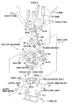
- FIG. 4 is a side view for explaining the four link mechanism 1 of the joint structure of the robot according to the embodiment of the present invention.
- the four link mechanism 1 includes, as shown in FIG. 4, the main link 5 for coupling the gimbal link 4 and the hand 8, and the sub link 6 provided crosswise with the main link 5.
- the four link mechanism 1 has the first to fourth links (5a, 5b, 6a, 6b) as coupling parts.
- the first link 5a is a coupling part between the main link 5 and the gimbal link 4, and is a rotational shaft for rotating the main link 5 in the longitudinal swing motion direction.
- the second link 5b is a coupling part between the main link 5 and the frame 81 of the hand 8 on the palm side.
- the third link 6a is a coupling part between the sub link 6 and the gimbal link 4, and is a rotational shaft for rotating the sub link 6 in the longitudinal swing motion direction.
- the fourth link 6b is a coupling part between the sub link 6 and the frame 81 of the hand 8 on the back side.
- one end of the main link 5 is coupled to the lateral shaft part 42 of the gimbal link 4 at the first link 5a.
- the other end of the sub link 6 is coupled to the main link coupling hole 8a (see FIG. 3) of the frame 81 of the hand 8 at the second link 5b.
- one end of the sub link 6 is coupled to the secondary shaft 45 of the gimbal link 4 at the third link 6a.
- the other end of the sub link 6 is coupled to the sub link coupling hole 8b (see FIG. 3) of the frame 81 of the hand 8 at the fourth link 6b.
- the sub link 6 is coupled to the hand 8 such that a line connecting the third link 6a and the fourth link 6b of the sub link 6 intersects with another line connecting the first link 5a and the second link 5b of the main link 5.
- the second link 5b is coupled to the frame 81 of the hand 8 on the palm side
- the fourth link 6b is coupled to the frame_81 of the hand 8 on the back side. This means that a relative position between the second link 5b and the fourth link 6b determines a swing angle (a tilt angle) of the hand 8.
- the link length ⁇ 1 of the main link 5 is configured to be greater than the link length ⁇ 2 of the sub link 6.
- the link length ⁇ 1 of the main link 5 is longer than the link length ⁇ 2 of the sub link 6, because wide rotational ranges of the main link 5 and the sub link 6 can be ensured in their rotational motions.
- the first rod 71 and the second rod 72 are coupled to the main link 5 via the respective universal joints 71a, 72a having the aligning functions (see also FIG. 2).
- the position at which the first rod 71 is coupled to the main link body 51a is the first coupling point 7a
- the position at which the second rod 72 is coupled to the main link body 51b is the second coupling point 7b.
- the first coupling point 7a and the second coupling point 7b are configured such that they are at equal distances from the lateral shaft 4b and the longitudinal shaft 4a of the gimbal link 4, respectively, and that the line connecting the first coupling point 7a and the second coupling point 7b is parallel to the lateral shaft 4b.
- the main link 5 can be rotated toward the back of the hand 8 in the longitudinal swing motion direction. If the first rod 71 and the second rod 72 are moved backward by equal distances, the main link 5 can be rotated toward the palm side in the longitudinal swing motion direction.
- the main link 5 can be rotated clockwise in the lateral swing motion direction (see FIG. 6(c)). If the first rod 71 is moved backward and the second rod 72 is moved forward, the main link 5 can be rotated counterclockwise in the lateral swing motion direction (see FIG. 6(a)).
- the longitudinal swing motion and the lateral swing motion are performed by moving the first rod 71 and the second rod 72 forward or backward.
- a first motor 91 and a second motor 92 drive the first rod 71 and the second rod 72, respectively and independently.
- the two motors are coordinated to perform the longitudinal swing motion and the lateral swing motion, so that the motors as well as the joint structure of a robot can be downsized.
- the motions in the longitudinal swing direction and the lateral swing direction can be performed just by coordinating and synchronizing the first rod 71 and the second rod 72. This ensures smooth and easily controllable motions.
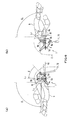
- FIG. 5 is side views each for explaining the longitudinal swing motion in the four link mechanism 1 according to the embodiment of the present invention.
- FIG. (a) shows a state where a hand is swung toward the back of the hand.
- FIG. (b) shows a state where the hand is straight with respect to the arm link.
- FIG. (c) shows a state where the hand is swung toward the palm of the hand.
- FIG. 6 is side views each showing the hand which is swung 90 degrees from the state of FIG. 5.
- FIG. (a) is a state where the hand is swung toward the back of the hand.
- FIG. (b) is a state where the hand is swung toward the palm of the hand.
- the longitudinal swing motion is described next with reference to FIG. 5.
- a line connecting the first link 5a and the third link 6a is referred to as a base line L 1 .
- a line connecting the first link 5a and the second link 5b is referred to as a main link line L 2 .
- a line connecting the third link 6a and the fourth link 6b is referred to as a sub link L 3 .
- a central axis line of the hand 8 is referred to as L 4 .
- An angle made by the main link line L 2 with respect to the longitudinal shaft 4a of the gimbal link 4 (see FIG. 2) is ⁇ 0 , in a state where the hand 8 is straight to the arm link 2 as shown in FIG. 5(b).
- the first rod 71 and the second rod 72 are moved forward by equal distances to rotate the main link 5 about the first link 5a toward the back of the hand 8 (in a counterclockwise direction) by an angle of ⁇ .
- the second link 5b of the main link 5 is also rotated toward the back of the hand 8.
- the fourth link 6b of the sub link 6 is also rotated about the third link 6a toward the back of the hand 8.
- the swing angle ⁇ 1 of the hand 8 is greater than the rotational angle ⁇ of the main link 5. Even with a slight rotation of the main link 5, the hand 8 is tilted to a great degree.
- FIG. 6 shows the state where the hand 8 is tilted to an angle of 90 degrees, like a human wrist.
- ⁇ is 46 degrees (see FIG. 6(a)).
- ⁇ is 32 degrees (see FIG. 6(b)).
- the rotational angle of the main link 5 is smaller than the tilt angle of the hand 8.
- the first rod 71 and the second rod 72 are moved backward to pivot the main link 5 about the first link 5a toward the palm of the hand 8 (in a clockwise direction with respect to the plane of the figure) by an angle of ⁇ .
- the swing speed of the hand 8 is increased to swing toward its back by an angle of ⁇ 2 , which is greater than ⁇ 1 .
- ⁇ 2 is greater than ⁇ 1 , because the link length ⁇ 1 of the main link 5 is configured to be greater than the link length ⁇ 2 of the sub link 6 (see FIG. 4).
- FIG. 7 is plan views each for explaining the lateral swing motion in the four link mechanism according to the embodiment of the present invention.
- FIG. (a) shows a state where the hand is swung in the counterclockwise direction with respect to the plane of the figure.
- FIG. (b) shows a state where the hand is straight with respect to the arm link.
- FIG. (c) shows a state where the hand is swung in the clockwise direction.
- the central axis line L 4 of the hand 8 is orthogonal to the lateral shaft 4b of the gimbal link 4 (see FIG. 2), in the state where the hand 8 is straight to the arm link 2 as shown in FIG. 7(b).
- the first rod 71 and the second rod 72 are moved backward and forward respectively, by equal distances to rotate the main link 5 about the longitudinal shaft 4a of the gimbal link 4 counterclockwise with respect to the plane of the figure by an angle of ⁇ .
- the hand 8 is also swung toward the same direction by the same angle of ⁇ .
- the first rod 71 and the second rod 72 are moved forward and backward, respectively, by equal distances to pivot the main link 5 about the longitudinal shaft 4a of the gimbal link 4 clockwise with respect to the plane of the figure by an angle of ⁇ .
- the hand 8 is also swung toward the same direction by the same angle of ⁇ , as shown in FIG. 7(c).
- the rotational angle ⁇ shown in FIG. 7(c) is equal to the rotational angle ⁇ shown in FIG. 7(a).
- the longitudinal swing motion of the hand 8 can be performed (see FIG. 4).
- the first rod 71 is moved forward or backward by a predetermined distance
- the second rod 72 is moved backward or forward by the same distance
- the lateral swing motion can be performed (see FIG. 5). Therefore, a combination of the longitudinal swing motion and the lateral swing motion of the hand 8 makes it possible to freely move the hand 8 in an oblique direction with respect to the longitudinal shaft 4a and the lateral shaft 4b, or in a circle.
- the longitudinal shaft serving as the first rotational shaft and the lateral shaft serving as the second rotational shaft are provided orthogonally to each other.
- the first rotational shaft (longitudinal shaft) and the second rotational shaft (lateral shaft) may just intersect with each other when viewed from above.
- the longitudinal swing motion and the lateral swing motion of the hand 8 can be performed by suitably adjusting traveling distances of the first rod 71 and the second rod 72.
- the hand 8 can be freely moved in an oblique direction with respect to the longitudinal shaft 4a and the lateral shaft 4b, or in a circle.
- the four link mechanism 1 is configured in a direction for the longitudinal swing motion, however, the present invention is not limited thereto.
- the four link mechanism 1 may be configured in a direction for the lateral swing motion.
- first rod 71 and the second rod 72 are coupled to the main link 5, in the different positions from the lateral shaft 4b, but in the positions parallel to the lateral shaft 4b and on both sides of the longitudinal shaft 4a.
- the first rod 71 and the second rod 72 may be coupled to the main link 5, in the different positions from the longitudinal shaft 4a, but in positions parallel to the longitudinal shaft 4a and on both sides of the lateral shaft 4b.
- the first rod 71 and the second rod 72 are coupled to the main link bodies 51a,51b, respectively, across the longitudinal shaft 4a.
- the first rod 71 and the second rod 72 may be coupled to the connecting parts 52,53, respectively, of the main link body 51a (or the main link body 51b), across the lateral shaft4b.
- the first motor 91, the second motor 92, or the like of the drive mechanism 9 may be arranged differently.
- the universal joints 71a,72a each having two degrees of freedom are used for coupling the first rod 71 and the second rod 72, respectively, to the main link 5.
- spherical joints 95a, 96a each having three degrees of freedom are used for coupling the first rod 71 and the second rod 72 to the output arms 95,96, respectively.
- the present invention is not limited thereto. Instead, the spherical joints may be used at the main link 5, and universal joints may be used at the output arms 95,96. In both cases, the spherical joints may be used, because a force in a twisting direction acts on the first rod 71 and the second rod 72 during their rotational motions.
Landscapes
- Engineering & Computer Science (AREA)
- Robotics (AREA)
- Mechanical Engineering (AREA)
- Manipulator (AREA)
- Transmission Devices (AREA)
Applications Claiming Priority (2)
| Application Number | Priority Date | Filing Date | Title |
|---|---|---|---|
| JP2006024289 | 2006-02-01 | ||
| PCT/JP2007/050893 WO2007088743A1 (fr) | 2006-02-01 | 2007-01-22 | Structure d'articulation de robot |
Publications (3)
| Publication Number | Publication Date |
|---|---|
| EP1857230A1 true EP1857230A1 (fr) | 2007-11-21 |
| EP1857230A4 EP1857230A4 (fr) | 2008-01-09 |
| EP1857230B1 EP1857230B1 (fr) | 2008-10-22 |
Family
ID=38327322
Family Applications (1)
| Application Number | Title | Priority Date | Filing Date |
|---|---|---|---|
| EP07707156A Not-in-force EP1857230B1 (fr) | 2006-02-01 | 2007-01-22 | Structure d'articulation de robot |
Country Status (7)
| Country | Link |
|---|---|
| US (1) | US20090071282A1 (fr) |
| EP (1) | EP1857230B1 (fr) |
| JP (1) | JP4971984B2 (fr) |
| KR (1) | KR100888078B1 (fr) |
| CN (1) | CN100588512C (fr) |
| DE (1) | DE602007000192D1 (fr) |
| WO (1) | WO2007088743A1 (fr) |
Cited By (3)
| Publication number | Priority date | Publication date | Assignee | Title |
|---|---|---|---|---|
| WO2016123083A1 (fr) | 2015-01-30 | 2016-08-04 | Irobot Corporation | Mécanismes de bras et de poignet de robot |
| EP2939800A4 (fr) * | 2012-12-28 | 2016-11-30 | Namiki Seimitu Houseki Kabushiki Kaisha | Manipulateur |
| EP3385571A4 (fr) * | 2015-12-03 | 2019-08-07 | Kawasaki Jukogyo Kabushiki Kaisha | Mécanisme d'entraînement à deux degrés de liberté |
Families Citing this family (23)
| Publication number | Priority date | Publication date | Assignee | Title |
|---|---|---|---|---|
| FR2930905B1 (fr) * | 2008-05-09 | 2010-10-01 | Bia | Cheville pour robot humanoide |
| US8498741B2 (en) * | 2009-09-22 | 2013-07-30 | Gm Global Technology Operations | Dexterous humanoid robotic wrist |
| JP5184502B2 (ja) * | 2009-12-22 | 2013-04-17 | 本田技研工業株式会社 | ロボットの関節機構の制御装置 |
| CN102848401B (zh) * | 2011-07-01 | 2015-04-22 | 山东科技大学 | 一种动力万向联轴节 |
| JP5722747B2 (ja) * | 2011-10-24 | 2015-05-27 | Thk株式会社 | ロボットの関節構造及びこの関節構造が組み込まれたロボット |
| CN103286791B (zh) * | 2013-07-07 | 2015-09-09 | 林佳杰 | 一种机器人关节结构 |
| CN103753527B (zh) * | 2014-01-07 | 2015-07-15 | 青岛华东工程机械有限公司 | 可俯仰物料夹持装置 |
| JP6087329B2 (ja) | 2014-09-19 | 2017-03-01 | Thk株式会社 | ロボットにおける回転駆動機構 |
| CN104260113A (zh) * | 2014-09-22 | 2015-01-07 | 珠海林顺机电有限公司 | 码垛机器人连杆装置 |
| JP6105024B2 (ja) | 2014-10-28 | 2017-03-29 | Thk株式会社 | ロボットにおける回転駆動機構 |
| KR101766576B1 (ko) * | 2016-01-14 | 2017-08-09 | 한양대학교 산학협력단 | 다자유도 구동장치 |
| JP1573749S (fr) * | 2016-01-29 | 2017-04-10 | ||
| CN109890579A (zh) * | 2016-10-28 | 2019-06-14 | 夏普株式会社 | 装置的可动结构、以及装置 |
| CN110382181B (zh) * | 2017-03-29 | 2022-10-28 | Groove X 株式会社 | 适合机器人的关节的接头构造 |
| CN107901075B (zh) * | 2017-11-28 | 2023-12-01 | 天津扬天科技有限公司 | 多自由度中空协作机械臂采用的关节模块 |
| CN108544529A (zh) * | 2018-04-09 | 2018-09-18 | 时枫娇 | 一种可精确调整的机器人及操作臂用多轴关节结构 |
| KR102246778B1 (ko) * | 2018-12-10 | 2021-05-03 | 한국기계연구원 | 손가락 기구 및 이를 포함하는 로봇 핸드 |
| CN109822618B (zh) * | 2019-04-18 | 2023-08-22 | 北京因时机器人科技有限公司 | 手腕结构和机器人 |
| JP7369111B2 (ja) * | 2019-08-07 | 2023-10-25 | 株式会社バンダイ | 可動構造及び人形体 |
| US20240316795A1 (en) * | 2023-03-21 | 2024-09-26 | Sanctuary Cognitive Systems Corporation | Robotic wrist with multiple degrees of freedom |
| US12358127B2 (en) * | 2023-03-21 | 2025-07-15 | Sanctuary Cognitive Systems Corporation | Robotic arm |
| CN117301114A (zh) * | 2023-09-27 | 2023-12-29 | 深圳市优世界机器人有限公司 | 一种腕臂结构及机器人 |
| US20250345952A1 (en) * | 2024-05-09 | 2025-11-13 | Timeback Incorporated | Ball Joint Differential for Robot |
Family Cites Families (15)
| Publication number | Priority date | Publication date | Assignee | Title |
|---|---|---|---|---|
| SE453974B (sv) * | 1984-05-18 | 1988-03-21 | Asea Ab | Industrirobot med tva kardanskt anordnande svengningsaxlar |
| US4805477A (en) * | 1987-10-22 | 1989-02-21 | Gmf Robotics Corporation | Multiple joint robot part |
| US5447403A (en) * | 1990-01-05 | 1995-09-05 | Engler, Jr.; Charles D. | Dexterous programmable robot and control system |
| JPH0569374A (ja) * | 1991-09-14 | 1993-03-23 | Toyota Central Res & Dev Lab Inc | 指モジユール、指モジユール構造、ロボツトハンドおよび指モジユールの信号検出取出方法 |
| CN1178495A (zh) * | 1995-11-17 | 1998-04-08 | 株式会社安川电机 | 多关节机器人的手腕机构 |
| JP3419637B2 (ja) * | 1996-07-24 | 2003-06-23 | 富士通株式会社 | 関節機構及びこれを使用するロボット |
| JPH10133733A (ja) * | 1996-10-31 | 1998-05-22 | Kokoro:Kk | アミューズメントロボットの動作教示方法及び動作教示装置 |
| US6030130A (en) * | 1997-07-07 | 2000-02-29 | George Paddock Ii, Inc. | Body mounted camera support system |
| US6244644B1 (en) * | 1999-01-25 | 2001-06-12 | The United States Of America As Represented By The Administrator Of The National Aeronautics And Space Administration | Compact dexterous robotic hand |
| US6418811B1 (en) * | 2000-05-26 | 2002-07-16 | Ross-Hime Designs, Inc. | Robotic manipulator |
| JP2002085353A (ja) * | 2000-09-11 | 2002-03-26 | Mamoru Mitsuishi | 遠隔診断システム |
| JP3974353B2 (ja) * | 2001-08-23 | 2007-09-12 | 三菱電機株式会社 | ジンバル機構及び関節機構 |
| JP2003170381A (ja) * | 2001-11-30 | 2003-06-17 | Seiko Epson Corp | 操作装置 |
| CN2595537Y (zh) * | 2002-12-26 | 2003-12-31 | 哈尔滨工业大学 | 多关节仿人型机器人手臂 |
| JP4589712B2 (ja) * | 2004-12-14 | 2010-12-01 | 本田技研工業株式会社 | ロボットの関節構造 |
-
2007
- 2007-01-22 WO PCT/JP2007/050893 patent/WO2007088743A1/fr not_active Ceased
- 2007-01-22 EP EP07707156A patent/EP1857230B1/fr not_active Not-in-force
- 2007-01-22 DE DE602007000192T patent/DE602007000192D1/de active Active
- 2007-01-22 JP JP2007525117A patent/JP4971984B2/ja not_active Expired - Fee Related
- 2007-01-22 US US11/887,918 patent/US20090071282A1/en not_active Abandoned
- 2007-01-22 CN CN200780000065A patent/CN100588512C/zh not_active Expired - Fee Related
- 2007-01-22 KR KR1020077017922A patent/KR100888078B1/ko not_active Expired - Fee Related
Cited By (6)
| Publication number | Priority date | Publication date | Assignee | Title |
|---|---|---|---|---|
| EP2939800A4 (fr) * | 2012-12-28 | 2016-11-30 | Namiki Seimitu Houseki Kabushiki Kaisha | Manipulateur |
| WO2016123083A1 (fr) | 2015-01-30 | 2016-08-04 | Irobot Corporation | Mécanismes de bras et de poignet de robot |
| EP3250348A4 (fr) * | 2015-01-30 | 2019-02-27 | iRobot Corporation | Mécanismes de bras et de poignet de robot |
| US10578197B2 (en) | 2015-01-30 | 2020-03-03 | Irobot Corporation | Robotic arm and wrist mechanisms |
| EP3385571A4 (fr) * | 2015-12-03 | 2019-08-07 | Kawasaki Jukogyo Kabushiki Kaisha | Mécanisme d'entraînement à deux degrés de liberté |
| US10828787B2 (en) | 2015-12-03 | 2020-11-10 | Kawasaki Jukogyo Kabushiki Kaisha | Drive mechanism of two degrees of freedom |
Also Published As
| Publication number | Publication date |
|---|---|
| DE602007000192D1 (de) | 2008-12-04 |
| US20090071282A1 (en) | 2009-03-19 |
| JPWO2007088743A1 (ja) | 2009-06-25 |
| WO2007088743A1 (fr) | 2007-08-09 |
| EP1857230B1 (fr) | 2008-10-22 |
| EP1857230A4 (fr) | 2008-01-09 |
| KR100888078B1 (ko) | 2009-03-11 |
| CN101213051A (zh) | 2008-07-02 |
| CN100588512C (zh) | 2010-02-10 |
| KR20070094827A (ko) | 2007-09-21 |
| JP4971984B2 (ja) | 2012-07-11 |
Similar Documents
| Publication | Publication Date | Title |
|---|---|---|
| EP1857230B1 (fr) | Structure d'articulation de robot | |
| EP1684950B1 (fr) | Mecanisme de cinematique parallele avec articulation spherique concentrique | |
| US7281447B2 (en) | Articulated mechanism comprising a cable reduction gear for use in a robot arm | |
| JP4235931B2 (ja) | パラレルリンクロボット | |
| US4805477A (en) | Multiple joint robot part | |
| US8245595B2 (en) | Two-axis non-singular robotic wrist | |
| RU2202467C2 (ru) | Конструкция механической руки антропоморфного робота | |
| JPS5816998B2 (ja) | 可撓性ロボツトア−ム | |
| US7086307B2 (en) | Parallel control arm with two branches | |
| JP2003039352A (ja) | ロボット | |
| CN118650648B (zh) | 灵巧手手指、灵巧手和机器人 | |
| US20040013509A1 (en) | Parallel kinematics mechanism with a concentric spherical joint | |
| US11602858B2 (en) | Thumb structure and robot | |
| JPH1086090A (ja) | 関節機構及びこれを使用するロボット | |
| KR100520264B1 (ko) | 양팔 로봇의 양팔 어깨 관절기구 및 이족 보행 로봇의양족 엉덩이 관절기구 | |
| JP2569277B2 (ja) | 空間3自由度の駆動装置 | |
| WO2020184574A1 (fr) | Structure d'articulation de robot | |
| JPH11254375A (ja) | パラレルロボット | |
| JPH0434610A (ja) | ジンバル装置 | |
| CN115091432A (zh) | 一种二移动一螺旋运动模式的三自由度并联机构 | |
| JPH0947995A (ja) | パラレルリンクマニピュレータ | |
| JPH07276270A (ja) | 平行リンク方式多関節ロボット | |
| JP7252797B2 (ja) | ロボットアーム | |
| JP4268035B2 (ja) | 産業用ロボットおよびその制御方法 | |
| JP2021130160A (ja) | 物体把持装置 |
Legal Events
| Date | Code | Title | Description |
|---|---|---|---|
| PUAI | Public reference made under article 153(3) epc to a published international application that has entered the european phase |
Free format text: ORIGINAL CODE: 0009012 |
|
| 17P | Request for examination filed |
Effective date: 20070910 |
|
| AK | Designated contracting states |
Kind code of ref document: A1 Designated state(s): AT BE BG CH CY CZ DE DK EE ES FI FR GB GR HU IE IS IT LI LT LU LV MC NL PL PT RO SE SI SK TR |
|
| AX | Request for extension of the european patent |
Extension state: AL BA HR MK YU |
|
| A4 | Supplementary search report drawn up and despatched |
Effective date: 20071211 |
|
| GRAP | Despatch of communication of intention to grant a patent |
Free format text: ORIGINAL CODE: EPIDOSNIGR1 |
|
| RIC1 | Information provided on ipc code assigned before grant |
Ipc: B25J 17/02 20060101AFI20080108BHEP Ipc: B25J 15/00 20060101ALI20080108BHEP |
|
| DAX | Request for extension of the european patent (deleted) | ||
| GRAS | Grant fee paid |
Free format text: ORIGINAL CODE: EPIDOSNIGR3 |
|
| GRAA | (expected) grant |
Free format text: ORIGINAL CODE: 0009210 |
|
| AK | Designated contracting states |
Kind code of ref document: B1 Designated state(s): DE FR GB |
|
| REG | Reference to a national code |
Ref country code: GB Ref legal event code: FG4D |
|
| REF | Corresponds to: |
Ref document number: 602007000192 Country of ref document: DE Date of ref document: 20081204 Kind code of ref document: P |
|
| PLBE | No opposition filed within time limit |
Free format text: ORIGINAL CODE: 0009261 |
|
| STAA | Information on the status of an ep patent application or granted ep patent |
Free format text: STATUS: NO OPPOSITION FILED WITHIN TIME LIMIT |
|
| 26N | No opposition filed |
Effective date: 20090723 |
|
| PGFP | Annual fee paid to national office [announced via postgrant information from national office to epo] |
Ref country code: FR Payment date: 20110128 Year of fee payment: 5 |
|
| PGFP | Annual fee paid to national office [announced via postgrant information from national office to epo] |
Ref country code: GB Payment date: 20110119 Year of fee payment: 5 |
|
| GBPC | Gb: european patent ceased through non-payment of renewal fee |
Effective date: 20120122 |
|
| REG | Reference to a national code |
Ref country code: FR Ref legal event code: ST Effective date: 20120928 |
|
| PG25 | Lapsed in a contracting state [announced via postgrant information from national office to epo] |
Ref country code: GB Free format text: LAPSE BECAUSE OF NON-PAYMENT OF DUE FEES Effective date: 20120122 |
|
| PG25 | Lapsed in a contracting state [announced via postgrant information from national office to epo] |
Ref country code: FR Free format text: LAPSE BECAUSE OF NON-PAYMENT OF DUE FEES Effective date: 20120131 |
|
| REG | Reference to a national code |
Ref country code: DE Ref legal event code: R084 Ref document number: 602007000192 Country of ref document: DE Effective date: 20131113 |
|
| PGFP | Annual fee paid to national office [announced via postgrant information from national office to epo] |
Ref country code: DE Payment date: 20210112 Year of fee payment: 15 |
|
| REG | Reference to a national code |
Ref country code: DE Ref legal event code: R119 Ref document number: 602007000192 Country of ref document: DE |
|
| PG25 | Lapsed in a contracting state [announced via postgrant information from national office to epo] |
Ref country code: DE Free format text: LAPSE BECAUSE OF NON-PAYMENT OF DUE FEES Effective date: 20220802 |