EP1857287A2 - Dispositif de décoration d'objets - Google Patents
Dispositif de décoration d'objets Download PDFInfo
- Publication number
- EP1857287A2 EP1857287A2 EP07006622A EP07006622A EP1857287A2 EP 1857287 A2 EP1857287 A2 EP 1857287A2 EP 07006622 A EP07006622 A EP 07006622A EP 07006622 A EP07006622 A EP 07006622A EP 1857287 A2 EP1857287 A2 EP 1857287A2
- Authority
- EP
- European Patent Office
- Prior art keywords
- holder
- carriage
- transport carriage
- transport
- movement
- Prior art date
- Legal status (The legal status is an assumption and is not a legal conclusion. Google has not performed a legal analysis and makes no representation as to the accuracy of the status listed.)
- Withdrawn
Links
Images


Classifications
-
- B—PERFORMING OPERATIONS; TRANSPORTING
- B41—PRINTING; LINING MACHINES; TYPEWRITERS; STAMPS
- B41J—TYPEWRITERS; SELECTIVE PRINTING MECHANISMS, i.e. MECHANISMS PRINTING OTHERWISE THAN FROM A FORME; CORRECTION OF TYPOGRAPHICAL ERRORS
- B41J13/00—Devices or arrangements of selective printing mechanisms, e.g. ink-jet printers or thermal printers, specially adapted for supporting or handling copy material in short lengths, e.g. sheets
- B41J13/10—Sheet holders, retainers, movable guides, or stationary guides
- B41J13/12—Sheet holders, retainers, movable guides, or stationary guides specially adapted for small cards, envelopes, or the like, e.g. credit cards, cut visiting cards
-
- B—PERFORMING OPERATIONS; TRANSPORTING
- B41—PRINTING; LINING MACHINES; TYPEWRITERS; STAMPS
- B41J—TYPEWRITERS; SELECTIVE PRINTING MECHANISMS, i.e. MECHANISMS PRINTING OTHERWISE THAN FROM A FORME; CORRECTION OF TYPOGRAPHICAL ERRORS
- B41J3/00—Typewriters or selective printing or marking mechanisms characterised by the purpose for which they are constructed
- B41J3/407—Typewriters or selective printing or marking mechanisms characterised by the purpose for which they are constructed for marking on special material
- B41J3/4071—Printing on disk-shaped media, e.g. CDs
-
- B—PERFORMING OPERATIONS; TRANSPORTING
- B41—PRINTING; LINING MACHINES; TYPEWRITERS; STAMPS
- B41J—TYPEWRITERS; SELECTIVE PRINTING MECHANISMS, i.e. MECHANISMS PRINTING OTHERWISE THAN FROM A FORME; CORRECTION OF TYPOGRAPHICAL ERRORS
- B41J3/00—Typewriters or selective printing or marking mechanisms characterised by the purpose for which they are constructed
- B41J3/407—Typewriters or selective printing or marking mechanisms characterised by the purpose for which they are constructed for marking on special material
- B41J3/4073—Printing on three-dimensional objects not being in sheet or web form, e.g. spherical or cubic objects
- B41J3/40731—Holders for objects, e. g. holders specially adapted to the shape of the object to be printed or adapted to hold several objects
Definitions
- the invention relates to a device according to the preamble of claim 1 and a method according to the preamble of claim 17.
- the European patent application EP 1 088 661 A1 describes a device with a plurality, each of a drive means moving transport carriage, which have a holder for supporting an object and with a plurality of decorating, in which the objects are driven by means of the transport carriage and decorated.
- objects may be, for example, CDs, DVDs, credit cards, telephone cards or similar items.
- the decoration includes any surface treatment such as coating, painting and / or printing of the object.
- the usual lot size is about 500 - 1,500 pieces, which are to be printed with the least possible time.
- the described generic device is often used, but the throughput in such a device is comparatively low.
- the device according to the invention is characterized in that the object holder at least one transport carriage attached to this movable is, wherein the movement direction has at least one component perpendicular to the direction of movement of the transport carriage and the at least two transport carriages are guided at least in sections on separate carriage tracks.
- a separation of the carriage tracks can be achieved, for example, by a parallel guidance of the transport carriages.
- the design according to the invention provides greater flexibility in the movement of the transport carriages both outside and inside the at least one decorating station, since the objects can be treated on different transport carriages in the same decorating stations, the carriages being designed so that they can be guided past one another , Due to the improved flexibility in the movement of the transport carriages, the throughput of the device according to the invention can be increased compared to conventional devices.
- the objects may be expedient for the objects to pass through the same object web during the decorating process in the at least one decorating station independently of the transport carriage.
- the effect of the different carriage tracks of the transport carriages on the object guide in a decorating station can be compensated by an adaptation of the respective holders, such that the position of the objects in the holders of different carriages during the decorating process is identical.
- the surface treatment does not have to be specially adjusted to the respective transport carriage.
- the device according to the invention may be expedient for the device according to the invention to comprise two transport carriages which are guided on slide paths running parallel to one another and offset from one another.
- a holder of a transport carriage for holding a plurality of objects is formed, wherein a separate receptacle is provided for each of the objects.
- the various object receptacles are arranged rigidly relative to one another, i. the relative position of the object images to each other is fixed.
- Such an object receptacle as a recess can be adapted to the geometric shape to be held object to provide a positive connection for the object, so that a positional fixation of the object to be ensured during transport.
- the object receptacle may also comprise a spindle which engages in the center hole of the CD / DVD.
- the plurality of object receptacles is arranged behind one another in the direction of movement of the transport carriage, so that the objects can be successively decorated when entering a decorating station.
- a plurality of object receptacles perpendicular to the direction of movement of the transport carriage, but in this case a plurality of surface treatment devices, such as print heads, are to be arranged side by side in a decorating station.
- a transfer device In order to remove the plurality of objects in a holder of a transport carriage in a single work step after the decoration of the objects, a transfer device can be provided which simultaneously picks up the objects and at the same time deposits them on a separating slide which can be constructed with respect to the support of the objects such as the transport carriage, that is, a holder having a plurality of in the direction of movement of the separating slide successively arranged object receivers.
- a movable collecting slide which, like the transport carriage, has a holder with a plurality of object receivers arranged one behind the other in the direction of movement, wherein a transfer device holds in the holder of the Collecting carriage held objects simultaneously and stores in the object receivers of the brackets of the transport carriage.
- the device according to the invention is suitable for a large number of surface treatments of objects, in particular for the printing of such objects. It may be advantageous if these are at least two decorating stations are included, which are arranged one behind the other in the direction of movement of a transport carriage. If the holder of a carriage is designed such that, depending on the position of the carriage, an object transported by it is located in a decorating station and another object transported by it in another decorating station, both objects can be decorated at the same time, in particular printed. With the movement of a single transport carriage, which moves several objects arranged one behind the other, it can be used e.g. the simultaneous printing of multiple objects in different printing stations are performed, with only a single drive, in particular a direct drive for a carriage is needed.
- a printing station can perform one of the multiplicity of conventional printing methods, such as offset printing, screen printing or non-contact printing, for example. like ink-jet printing or laser printing. It depends on the printing method used or the geometric arrangement of the printing unit to the objects, whether the object to be printed moves during the printing process in the printing station on the transport through the carriage or is held stationary. In the first case, the movement of the object is then adapted to the printing process. This is familiar to the expert so far, so it need not be discussed further.
- the drive device of a transport carriage comprises a direct drive such as a linear motor.
- the transport carriage may comprise either the primary part or the secondary part of the linear motor.
- a construction has been found in which the coils of the linear motor in the transport carriage and magnets are arranged in the stationary part of the device. It should be noted, however, that for driving a transport carriage for the device according to the invention, other constructions are executable, such as a drive via a toothed belt, a rack, a screw, a chain or by means of an air cylinder.
- an adjusting device for moving the holding device on the transport carriage with a movement component perpendicular to the direction of movement of the carriage, an adjusting device can be provided, which in particular can comprise a drive, which is coupled to a transmission, which is on the output side in operative connection with the holding device. It is expedient if the adjusting device moves the holder substantially perpendicular to the movement device of the carriage. Preferably, at least one end position of the holder is provided, on which the movement of the holder can be locked or locked. This blocking or locking has the advantage that after determining no force must be expended to the holder in the specified position, which for example represents the printing position, is needed.
- the adjustment means may comprise two dead spots, i. Provide reversals of the bracket.
- it can also be provided to design the adjusting device such that at least one of these reversing positions has a blocking or locking effect.
- This can be achieved, for example, by the use of a push crank as a transmission device, which is driven by a motor and is in operative connection with the holder in order to move it between the two reversal positions.
- a crank handle can be replaced for example by a crank roller or a sliding loop.
- a blocking effect in the region of at least one reversal position is achieved in that the adjustment due to the gear used there has a very high translation, ideally an infinite high translation, so that the holder can be kept without major or completely without effort in the reverse position.
- the holder near the reversing positions has a low speed compared to the maximum adjustment speed of the holder. By this measure, it is ensured that the holder approaches the end positions with a small impulse, so that hardly any shocks are transmitted to the device from the holder when reaching the end positions.
- the holder may be, for example, a stepper motor, an electromechanical motor, a fluid motor or a piezo motor.
- an energy store acting at least in each end position can be provided. It can be provided that the energy storage stores potential energy when the holder is in an end position. This stored energy can then be made available during the movement of the holder from an end position to its acceleration. Particularly advantageously, the energy storage can be designed so that it emits mechanical energy to the holder for accelerating the holder from an end or reverse position and absorbs kinetic energy of the holder before reaching an end or reverse position to decelerate this.
- Such an energy store may be, for example, a coil spring or an air spring.
- the device according to the invention can have an elongated base, which is in particular of cuboid shape, wherein guide means are arranged on two opposite longitudinal sides, which cooperates with complementarily designed guide means for fixing the carriage path of a transport carriage. It is understood that this base may comprise several parts.
- the cooperating guide means provide the positive guidance of the transport carriage, for example on a linear path.
- the structural design for a transport carriage in a device according to the invention can be kept comparatively low, if this has a vertically extending base plate on which a carrier, in particular in the form of at least one carrier rail is arranged, which carries a holding plate, which is substantially perpendicular to Base plate of the transport carriage extends.
- a carrier in particular in the form of at least one carrier rail is arranged, which carries a holding plate, which is substantially perpendicular to Base plate of the transport carriage extends.
- the carrier is slidably disposed in the plane of the base plate.
- the invention solves the problem indicated by a method for decorating objects, in which at least two transport carriages are each moved by a drive device, and an object is held by a holder, which itself is supported by the transport carriage, wherein the holder of a transport carriage is moved substantially perpendicular to the direction of movement of the carriage and the at least two transport carriages are at least partially offset from each other.
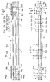
- a printing device 1 is shown in an overview in the figures 1 and 2 in the cutout, wherein Fig. 1 shows the device in a side view and Figure 2 in a plan view.
- the device has an elongate, rectilinear structure defined by a base member 10 which is substantially parallelepipedal and supported by legs 11 at the bottom.
- a respective slide 16a, 16b is provided, which is mounted with a base plate 18a, 18b substantially along the entire longitudinal extent of the base member 10 movable.
- the respective base plate 18a, 18b are displaceable in the vertical direction support rails 24a, 24b; 24c, 24d attached, which carry a holding plate 26a, 26b, see Figure 1.
- This plate has, as shown in particular in Figure 2, a plurality of object receptacles 6, the are arranged one behind the other in the direction of movement of the respective carriage.
- the receptacles each have a short pin which engages straight into the respective center hole of the CD.
- the respective holding plate 26a, 26b rigidly fastened to the carriers is accordingly adjustable in height.
- the carriers 24a, 24b; 24c, 24d respectively attached to a longitudinal side of the holding plates 26a, 26b and extend substantially perpendicular to the direction of movement of the respective base plate 18a, 18b.
- the two carriages 16a, 16b are constructed in mirror image to the plane of the drawing with reference to FIG.
- the carriages are thereby guided and held on the base element 10 by vertically spaced guide rails extending in the longitudinal direction of the base element.
- Both carriages are moved by independently operating direct drives, which are designed as linear motors in the described embodiment.
- the movement of the carriages in the longitudinal direction of the base element or the movement of the holding plates 26a, 26b in the vertical direction are coordinated with each other. Details concerning the drives of the carriages and the adjusting drives of the holding plates will be discussed below with reference to FIGS. 3 and 4.
- the printing device 1 is designed to carry out a four-color printing, wherein before the actual printing a primer is applied to the objects and after the actual printing the surface is sealed by the application of a lacquer layer.
- the primer and the varnish are each applied to the CD by a screen printing station 54a, 54b, while four inkjet printhead stations 50a to 50b successively arranged in the direction of movement of the carriages are provided for the four-color printing, each of which are provided for printing the object with one of the four basic colors.
- a drying station 52a to 52d is provided between the individual printing stations in the direction of movement of the carriage, in each of which the applied color ink is dried by means of a UV tube before printing with the subsequent color.
- the respective carriage which carries the object which has just been surface-treated, stands still, since the screen-printing squeegee not shown in the figures moves perpendicular to the direction of movement of the transport carriages 26a, 26b.
- the print heads (not shown in the figures) of the print stations 50a to 50d are fixed during the printing process and the respective print object (CD / DVD) is moved under the print head at a speed adapted to the printing process.
- the longitudinal position of the carriage and thus the actual position of the object or objects is detected by means of a measuring arrangement, so that the movement of the carriage under the print head can be synchronized with the printing operation.
- the ink jet heads used each have at least one printing line, which is arranged perpendicular to the direction of movement of the carriage and has an extension which is not smaller than the width of the area of the object to be decorated with transverse to its transport direction.
- a print line has nozzles spaced longitudinally of the print line from which the ink is ejected.
- the operating parameters of the drying stations 52a-52d are therefore adapted to the printing speed in the printing stations 50a-50d in order to allow a first object to be dried in the drying station and a second object to be printed in a printing station to be printed same speed can be moved. This is the prerequisite for the fact that both objects with the same transport carriage can be moved by the cascading of printing stations and drying stations.
- Both carriages 26a, 26b can be retracted successively into the stations for the printing process, the object webs, ie the web which describes an object which is passed through a station during the printing process, being the same for all objects.
- the inventive design of the printing device described it is possible that the two carriages and thus the holding plates 26a, 26b can be guided past one another.
- the movement of both carriages is not limited by the position or movement of the respective other carriage, since the two holding plates 26a, 26b are adjustable relative to each other so that they do not collide.
- both carriages can be arranged in their position so that the two holding plates 26a, 26b are located within the same printing station, but only one of the holding plates can be in a printing position, ie in a position in which a held by a receptacle 6 Object is printed.
- the holding plate of the other transport carriage in another horizontal plane, which will be discussed in more detail below with reference to Figure 5.
- objects of both carriages held by the receptacles 6 of the holding plates 26a, 26b may be simultaneously surface-treated in different stations, i. printed and / or dried here.
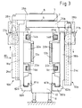
- FIG. 3 shows the device according to the invention in an end view.
- the device for decorating objects has an elongated, substantially cuboidal base 10, which is supported with legs 11 on the ground and above which the treatment stations, not shown here are arranged for the objects to be decorated.
- the stationary part 12a, 12b of a linear motor is mounted, which run on the base 10 over the longitudinal extent thereof.
- a guide rail 14a, 14c; 14b, 14d attached to the base 10, each extending parallel to the stationary parts 12a, 12b of the linear motor.
- each side of the base 10 there is provided a carriage 16a, 16b slidably disposed along the same and each having a carriage base plate 18a, 18b.
- Each of these plates carries on its base 10 side facing the movable part 20a and 20b of the linear motor, which cooperates respectively with the associated stationary part 12a and 12b for driving the carriage in a conventional manner.
- two guide shoes 22a, 22b and 22c, 22d are mounted on the plate 18a, 18b, which engage around the respectively opposite guide rail 14a, 14b and 14c, 14d and these.
- both carriage base plates 18a, 18b have inwardly directed U-shaped sections 60a, 60b directed towards the base 10, at their respective inner legs 61a, 61b, an unillustrated optical sensor is arranged.
- a projection 62a, 62b projects, which extends as the guide rails substantially over the entire movement distance of the carriage in the longitudinal direction of the base 10.
- the projections 62a, 62b have, on the side facing the sensor on the respective leg 61a, 61b, a division which is optically scanned by the sensor.
- the measuring system is designed to determine the actual position of the respective carriage with an accuracy better than 1 micron.
- Both transport carriages 16a, 16b each comprise a holding plate 26a, 26b, which is adjustably mounted on the respective base plate 18a, 18b of the associated transport carriage 16a, 16b.
- each carriage comprises the respective support plate 26a, 26b carrying and fixedly connected to the support rails 24a, 24c, which by means of an adjusting device.
- 27a, 27b are movable perpendicular to the direction of movement of the carriage.
- FIG. 4 shows the transport carriage 16a held by the base 10 and comprising the carriage base plate 18a and the two carrier rails 24a, b.
- the holding plate 26a is screwed, which has a plurality of object receptacles 6, which receives the objects to be decorated.
- the support rails 24a, 24b are movably connected to the carriage base plate 18a so as to be vertically movable toward the base plate.
- the movement of the holding plate 26a or the carrier rails 24a, 24b takes place in a positive guidance of the rails 24a, 24b in spaced guide rails 25a, 25b perpendicular to the direction of movement of the transport carriage 16a, wherein the guide rails 25a, 25b respectively in complementary formed portions of the associated support rail 24a , 24b intervene.
- a pneumatic swing motor 28a is provided, which is fixed to the base plate 18a of the carriage.
- the pneumatic motor 28a has inside a manner not shown on a swing-wing, which can be rotated by supplying air into one of two chambers.
- the swivel angle is infinitely adjustable, with an end position adjustment via stop screws, which interact with a stop lever on the swing wing to determine the two end positions.
- the axis of the swing wing extends as drive shaft 30 from the pneumatic swing motor 28a out. It drives a toothed belt 32 via a toothed wheel 31, which in turn moves a shaft 34 via a toothed wheel, wherein a predetermined reduction ratio is set by appropriate selection of the toothed wheels 31, 33 of the drive shaft 30 or of the shaft 34.
- the shaft 34 is mounted in two plate-shaped ball bearing support 36a, 36b, which are rigidly secured to the carriage base plate. The shaft 34 extends beyond the ball bearing supports 36a, 36b, at both ends of which a crank 38a, 38b is fixed in each case. In this respect, the two cranks are offset by the shaft 34 in a synchronous rotational movement.
- a pin 39a, 39b is respectively arranged, which receives the bearing of a joint head 40a, 40b, which is one of the two ends of a push rod 42a, 42b.
- the push rods 42a, 42b have, at their second ends, respective rod ends 44a, 44b, whose pivot bearings receive pins 43a, 43b, which extend laterally out of the two carrier rails 24a, 24b.
- cranks 38a, 38b shown in Figure 4 out of the plane of the drawing the push rods 42a, 42b and thus the support rails 24a, b moves down.
- the positive guidance of the carrier rails takes place so that the movement of the carrier rails is within the plane of the drawing.
- the adjusting device described defines two reversal positions or dead centers of the carrier rails and thus the holding plate 26a.
- the motor 28a rotates the cranks 38a, 38b downward from the top dead center shown in the drawing to the bottom dead center.
- a stable equilibrium position represents the top dead center is a labile operating point.
- the slightest pivotal movements of the crank cause the entire vertical movement of the support plate and support rails 24a, b, moving towards the base plate, to move downwards due to a vertically downward force acting on the support plate 26a, when the motor 28a has no counterforce to maintain of top dead center.
- the power transmission through the crank is infinitely high, so that the motor 28a only has to apply a very small moment in order to determine, ie to lock, this dead center.
- cranks are in the described embodiment as symmetrical cranks 38a, b formed, inasmuch the distance of the translational movement of the rotor rails and thus the height displacement of the holding plate 26a is set by the double distance between the attachment point of the pin of a condyle 40a, b to the crank 38 a, b to the center of the shaft 34.
- the set in the pivot motor 28a two end positions on the stop screws correspond to the two dead positions of the cranks 38a, 38b.
- the pivoting wing rotates about 180 ° in the motor 28a of the described embodiment, so that the gear ratio of the gears 31 and 33 shown in Figs. 3 and 4 is not to scale.
- the impact of the stop lever against the stopper screws is damped by means of a cushioning, so that due to the low mass of the pivoting blade when reaching the top or bottom dead center hardly shocks are transmitted to the support plate 26 a, which cause vibration of the support plate and in this way could interfere with the printing process.
- the essential part of the kinetic energy of the entire facial expression, consisting of support plate and rotor rails is received by mechanical compression springs 46a to 46d, which are connected at one end to the base plate 18a and at the other end with a rotor rail 24a, 24b and the holding plate 26a.
- the springs are clamped so that they have a bias in each operating situation and thus act as a compression spring.
- the lower springs 46a, 46b are each clamped between two counterplates 48a, 48b and 49a, 49b.
- the lower counter-plate 48a, 49a rigidly attached to the respective associated runner rail 24a, 24b and the upper counter-plate 48b, 49b rigidly attached to the carriage base plate 18a.
- the upper compression springs 46c, 46d are attached at one end to the carriage base plate 18a and at their other end directly to the holding plate 26a.
- cranks Since the cranks are in their upper dead center position in the position of the holding plate 26a shown in FIG. 4, only a small torque to be applied by the pneumatic motor 28a is required to keep the support plate 26a stable even under an external force such as during the printing operation to hold the illustrated upper reversal position. If the cranks are moved out of the specified upper dead center, the prestressed compression springs 46a-46d support the lowering of the retaining plate, the lower spring pairs counteracting the upper spring pairs. In the situation described, the greater force is exerted by the lower springs 46a, 46b, since they have a greater pretension than the upper springs 46c, 46d.
- the adjustment described adjustment for height adjustment of the holding plate 26a, 26b provides two end positions, which are set by the use of the crank as reversal positions and represent blocking positions that can be maintained with a small force of the motor 28a.
- the variable displacement motor may also be an electric motor such as a stepper motor or other actuator. It is particularly useful if at least one end position of the height adjustment has a blocking position, which is precisely defined and is maintained during the printing process.
- an energy storage device such as a spring, a substantial part of the energy required for the movement of the holder to accelerate the holding plate can be taken from the energy store and fed back when braking. As a result, the drive motor can be kept small and light.
- a cam roller drive or a thrust loop is used instead of a slider crank drive, which provide in a similar manner two reversal positions of the retaining plate with blocking effect.
- the transport carriage 16a moves first from the position shown in Figure 2 to the right, such that the in Direction of travel last object shot, respectively stored therein CD is in printing position in the screen printing station 54b.
- This printing position is characterized on the one hand by a prescribed position of the CD in question in the direction of movement of the carriage to the printing station and on the other hand is that the holding plate 26a is in the upper reversing position, which is a blocking position as described.
- the primer is performed on the first CD in the direction of movement as described above with stationary carriage. Thereafter, the carriage moves by a predetermined distance further to the left until the second object recording in the direction of movement respectively the second CD is in a printing position in the screen printing station 54b, so that it can be primed with a fixed slide. This process continues until the last, in the current direction of movement CD in the back of said printing position in the screen printing station 54b comes to rest, so that they can be primed.
- the carriage 26a moves through the drying station 56 at a uniform speed, which has a UV tube for drying the applied primer.
- the drying of the CDs in the station 56 accordingly takes place during the movement of the carriage through the station.
- the holding plate 26a of the carriage 16a is now brought from the lower locking position by actuation of the pivot motor with the aid of the energy stored in the springs in the upper dead center, which represents the horizontal pressure and drying position of the holding plate 26a.
- the carriage drives the holding plate 26a, respectively the CDs held in the object holders 6, uniformly through the successively arranged printing stations 50a-50d, each having a stationary ink-jet printhead. After each of the colors has been applied to a CD, in the downstream drying station 52a-d, a predrying of this ink takes place before the respective CD passes through the subsequent printing station.
- the four-color printing is completed for the four CDs mounted on the platen 26a. They are in turn subsequently retracted by stepwise movement of the carriage in the paint station 54a and painted with a stationary carriage. After all four CDs have been successively painted in the paint station 54a, they are subsequently successively moved uniformly through the drying station 56. Thereafter, the printing operation of the CDs on the carriage 16a is completed and the CDs can be removed from the receiving plate 26a, which will be discussed in more detail below.
- the printing device Due to the design of the printing device according to the invention, it can be operated with a plurality of carriages which move simultaneously and transport a plurality of CDs at a time. It should be emphasized that, for example, an embodiment with three or four carriages is within the scope of the invention, wherein on one longitudinal side of the base then a plurality of carriage tracks may be arranged, for example, to the center axis of Base element have a different distance.
- the printing station 1 has two such carriages which are each movably mounted on a longitudinal side of the base element 10.
- Each of these carriages can perform the printing pass just described in the device, collisions can now be avoided by the respective holding plates 26a, 26b can be offset in height by the respective adjusting means 27a, 27b in the juxtaposition of the carriage, see Figure 3.
- FIG. 3 Such a situation is shown in FIG.
- the carriage 16b is just in the direction of movement with its first recording in the printing position in the painting station 54a, while the carriage 16a moves in the opposite direction in the figure to the right to perform the described four-color printing.
- the retaining plate 26a has moved to the lower reversal position with which the carriage also passes through the printing stations 50d-50a. After reaching the end position on the right side in the drawing, as described, the holding plate 26a is moved to its printing position, i. in their upper reversal position, so that then the four-color printing can be performed. Simultaneously, the carriage 16b moves further to the left in the opposite end position, where the printed, painted and dried CDs are removed. At this extraction location, the recordings 6 are also equipped with still unprinted CDs, so that the entire printing process can start again from the beginning.
- the arrangement of the receptacles 6 on the carriages 16a, 16b is adapted to the distance D1 of the two screen printing stations 54a, 54b in the event that no clear coat is present in the screen printing station 54a after the four-color printing of the CDs described above has been carried out must be applied.
- both screen printing stations 54a, 54b are used to apply the primer.
- arranged in the direction of movement of the carriage first and third and the second and fourth shots on the holding plate are spaced so that their centers have a distance D1, which just the spacing shown in Figure 2 of the printing positions in the two screen printing stations 54a , 54b corresponds.
- the primer can be applied simultaneously to the first and third CD on the recording of the carriage and subsequently after the transport of the carriage by the distance D2 on the second and fourth CD.
- the resolution of the ink jet heads used in the printing stations 50a-50d may not be sufficient for the required print quality.
- FIGS. 6-8 the design of the part of the printing device according to the invention for loading the receptacles 6 with objects to be printed on the carriage or for removing the printed objects from the receptacles of the carriages will be described.
- the figures show an input and output station 150, which adjoins the left in the base member 10 shown in Figures 1 and 2, wherein the base member extends into the input and receiving station, so that the respective carriage can drive into it.
- the parking position of the respective transport carriage or the respective holding plate in the input and output station is indicated by the reference numeral 140. In this position of its holding plate drives a carriage equipped with printed CDs.
- the input and output station 150 has an input section arranged in the upper region of the illustration in FIGS. 6-8 and an output section arranged in the lower region of the figure.
- CDs to be printed are stacked on four CD input disks 72, which centrally have a long spindle extending through the center hole of the CDs.
- the CD input discs 72 are circumferentially disposed on an input carousel 70. After the CDs discarded on one of the CD input discs are removed, the input carousel rotates to the next filled CD input disc, which is then deflated.
- the input section further comprises a collecting carriage 80, which has a receiving plate which is identical to that of a transport carriage.
- the collecting carriage also CD recordings 82, which are arranged on the receiving plate in the same manner as those of the transport carriage to each other.
- the collecting carriage can be moved stepwise parallel to the longitudinal extent of the parking position 140 of a transport carriage by means of a stepper motor 84.
- the dispensing area has a singling carriage 90, which in turn, like the collection carriage, has CD receptacles, the spacing of the receptacle being again identical to that of a transport carriage.
- the separating slide is also movable via a stepping motor 94 parallel to the collecting slide or transport slide. Collecting carriages and separating carriages are moved independently and stepwise in the described embodiment. The step size is determined by the distance between two receptacles 82, 92 on the respective carriage 80, 90.
- accumulation carriages and singulation carriages are moved only within the input and output station.
- the dispensing area has a receiving carousel 100 which includes four CD receiving plates 102 spaced circumferentially. Each plate in turn has a spindle on which the issued CDs are strung. If a CD-receiving plate is filled to the end of the respective spindle, the carousel 100 rotates to the next CD-receiving plate, which is subsequently filled with printed CDs.
- each input CD is subjected to a so-called IdentCheck.
- the IdentCheckteller 78 (FIG. 7) serves this purpose, to which the CD taken from a CD input disk is first placed and subsequently the identity of the relevant CD is detected. For this purpose, each CD has a code mark, which uniquely identifies the data content. If the verification of the identity of the respective CD reveals that it does not correspond to the set printing process, the CD is placed on the ejector 76.
- a so-called PrintCheck is performed, in which the print quality is checked.
- the CD to be checked is placed on a PrintCheck carousel 107, which is constructed in an oval shape and symmetrically to a rotational axis 109 of the carousel has two PrintCheckteller 108a, 108b.
- the CD to be checked is placed on the plate, which is provided with the reference numeral 108a.
- the PrintCheck carousel 107 rotates 180 ° with the axis of rotation 109 perpendicular to the plane of the drawing, causing the CD device in the receiving area of a camera 110, the recording of which is processed by the printing surface.
- the PrintCheck carousel 107 rotates back to the starting position in which the tested CD is removed.
- the CD is placed on one of the four CD-output tray 102, otherwise on the Ausschussteller 106.
- the one or more color print heads are moved so that an optimal overlay of the single monochrome prints is achieved.
- the individual color print heads are preferably mounted displaceably in a plane, wherein the heads can be readjusted in their position in response to the detected printing error by a control during operation of the device. Such readjustment may be necessary, for example, after a printhead change.
- the storage of CDs in the input and output station 150 is performed by a CD transmitter 120 which is movably mounted on a horizontal strut 124 of a portal 122.
- the movement of the CD transmitter 120 is perpendicular to the longitudinal extent of the carriages, for example the collecting carriage.
- the CD transformer 120 is reciprocated stepwise in the direction of the arrow C, wherein the step size is equal in both directions and corresponds to half the distance of the center lines of the receptacles 82, 92 of the collecting tray or the separating slide. This step size is identical to the distance between the center lines of separating slide and collecting slide to the center line of the recordings of a transport carriage, as far as it is in the parking position 140 with its support plate.
- the CD transmitter in the described embodiment has a total of twelve vacuum injectors with which the CDs can be picked up by suction.
- two spaced straight by the pitch of the CD transmitter rows of injectors 126 are arranged in the central region of the transformer, which serve for simultaneously lifting the arranged on one of the three carriages CDs.
- the lifted CDs are placed after moving the CD transmitter by one step length in the drawing plane down to an adjacent carriage.
- the CDs arranged in the collecting carriage 80 can be picked up and stored in the transport carriage 16a, 16b or the CDs arranged in the transport carriage can be picked up and deposited in the singling carriage 90 in a single work step.
- the CD transmitter 120 has two further injectors on the plate-shaped base both in the input and in the output region, one of which is pivotable. Due to the stepwise movement of the CD transmitter between two operating positions, a single point is assigned to each individual vacuum injector, from which CDs are recorded and a single point within the input and output station 150 on which CDs are stored. Only the injector 126, which is attached to the pivot arm 128 in the input area and the injector 126, which is attached to a pivot arm 127 in the output area, have two alternative storage locations, which are selected depending on the result of IdentChecks or checking the print quality.
- FIG. 6 shows an operating situation in the input area in which, on the one hand, a CD is placed on the identification deck and the CD previously checked on the identification deck is placed on the collecting rack 80.
- the separating carriage 90 still has two printed CDs.
- the CD previously recorded by the separating carriage is placed on the print check plate 108a of the PrintCheck carousel 107, at the same time the pivoting arm 127 checks a positive result CD on a CD output tray 102 of the output carousel 100 from.
- the collection carriage 80 moves one step to the right and the singulation carriage 90 one step to the left.
- the CD transmitter 120 then clocks up by the described step size in the drawing figures, so that the operating situation shown in Figure 7 results.
- the upper vacuum injector 126 in the input area is currently picking up a CD from the CD input tray 72, at the same time the vacuum injector 126 attached to the swing arm 128 receives a CD from the ID tray 78.
- the outermost injector 126 on the pivot arm 127 picks up a CD checked for its print image while the adjacent vacuum injector picks up a CD from the singulation carriage 90.
- the CD transmitter can step down one step, placing the checked input CD on the collection slide and the checked output CD on the output carousel.
- the individual vacuum injectors of the CD transmitter work in the described embodiment in a common plane, ie, the CD transformer 120 moves as described stepwise only in one plane.
- a CD lifter 74 is provided in order to bring CDs on one of the CD input disk 72, from which CDs are taken, in the receiving plane of the vacuum injector 126.
- the described reciprocating movement of the CD transmitter on the one hand in a single step a retracted into the input and output station 150 transport carriage loaded with CDs to be printed or the printed CDs are removed. Subsequently, the separating slide is emptied or the collecting slide recharged, so that the input and output station for the next incoming transport carriage is prepared again.
Landscapes
- Engineering & Computer Science (AREA)
- Manufacturing & Machinery (AREA)
- Ink Jet (AREA)
- Dot-Matrix Printers And Others (AREA)
- Specific Conveyance Elements (AREA)
- Vehicle Waterproofing, Decoration, And Sanitation Devices (AREA)
- Printing Methods (AREA)
- Coating Apparatus (AREA)
- Handling Of Cut Paper (AREA)
Applications Claiming Priority (1)
| Application Number | Priority Date | Filing Date | Title |
|---|---|---|---|
| DE102006023349A DE102006023349A1 (de) | 2006-05-17 | 2006-05-17 | Vorrichtung zum Dekorieren von Objekten |
Publications (1)
| Publication Number | Publication Date |
|---|---|
| EP1857287A2 true EP1857287A2 (fr) | 2007-11-21 |
Family
ID=38440280
Family Applications (1)
| Application Number | Title | Priority Date | Filing Date |
|---|---|---|---|
| EP07006622A Withdrawn EP1857287A2 (fr) | 2006-05-17 | 2007-03-30 | Dispositif de décoration d'objets |
Country Status (11)
| Country | Link |
|---|---|
| US (1) | US20070269249A1 (fr) |
| EP (1) | EP1857287A2 (fr) |
| JP (1) | JP2007307907A (fr) |
| CN (1) | CN101073955A (fr) |
| AU (1) | AU2007201457A1 (fr) |
| BR (1) | BRPI0702289A (fr) |
| CA (1) | CA2587231A1 (fr) |
| DE (1) | DE102006023349A1 (fr) |
| MX (1) | MX2007005848A (fr) |
| RU (1) | RU2007118297A (fr) |
| TW (1) | TW200743581A (fr) |
Cited By (5)
| Publication number | Priority date | Publication date | Assignee | Title |
|---|---|---|---|---|
| WO2011069596A1 (fr) * | 2009-12-07 | 2011-06-16 | Andrea Mayrhofer | Imprimante |
| EP2658722B1 (fr) | 2010-12-30 | 2016-09-07 | Sicpa Holding Sa | Imprimante à jet d'encre pour cartes |
| WO2017203022A1 (fr) * | 2016-05-27 | 2017-11-30 | MGI Digital Technology | Dispositif et procédé de transport de substrats dans une machine d'impression |
| EP3476600A1 (fr) * | 2017-10-25 | 2019-05-01 | Angelo Schiestl | Imprimante |
| CN115973692A (zh) * | 2023-01-20 | 2023-04-18 | 揭阳市晨晖机械有限公司 | 一种用于产品加工的转盘及移印机 |
Families Citing this family (15)
| Publication number | Priority date | Publication date | Assignee | Title |
|---|---|---|---|---|
| DE202011111054U1 (de) * | 2011-11-21 | 2018-11-14 | Krones Ag | Vorrichtung zum Ausstatten von Behältern |
| DE102014218314B4 (de) | 2014-09-12 | 2017-06-01 | Kba-Kammann Gmbh | Verfahren zum Betreiben einer Transportvorrichtung für mehrere in einer Bearbeitungsmaschine zu bearbeitende und/oder dort bearbeitete Objekte |
| DE102014218313B4 (de) | 2014-09-12 | 2017-05-04 | Kba-Kammann Gmbh | Transportvorrichtung für in einer Bearbeitungsmaschine zu bearbeitende und/oder dort bearbeitete Objekte |
| DE102014218306A1 (de) | 2014-09-12 | 2016-03-17 | Kba-Kammann Gmbh | Vorrichtung zur Bereitstellung von thermoplastischer Druckfarbe an einer Druckform eines Druckwerks |
| DE102014218308B4 (de) | 2014-09-12 | 2021-12-23 | Kba-Kammann Gmbh | Transportvorrichtung für in einer Bearbeitungsmaschine zu bearbeitende und/oder dort bearbeitete Objekte |
| DE102014218310B4 (de) | 2014-09-12 | 2017-06-01 | Kba-Kammann Gmbh | Transportvorrichtung für in einer Bearbeitungsmaschine zu bearbeitende und dort bearbeitete Objekte |
| DE102016220970B4 (de) | 2016-10-25 | 2022-12-08 | Kba-Kammann Gmbh | Druckmaschine zum Drucken mindestens eines Druckbildes auf eine Bedruckstofffläche |
| DE102017206936A1 (de) | 2017-04-25 | 2018-10-25 | Kba-Kammann Gmbh | Verfahren zum Bedrucken von jeweils eine Mantelfläche und eine Grundfläche aufweisenden Körpern und Vorrichtung zum Überführen mindestens eines solchen Körpers von einer ersten Bearbeitungsposition in eine zweite Bearbeitungsposition |
| WO2018208773A2 (fr) * | 2017-05-09 | 2018-11-15 | Entrust Datacard Corporation | Transport de cartes-documents dans un système de traitement de cartes |
| CN109625790A (zh) * | 2018-12-13 | 2019-04-16 | 湖北枫林酒业酿造有限公司 | 一种酒瓶传送风干装置 |
| FR3103404B1 (fr) * | 2019-11-26 | 2024-02-23 | Antonio Alves | Dispositif de traitement de plusieurs faces d’objets, et procédé de traitement correspondant |
| CN112590437B (zh) * | 2020-12-30 | 2022-08-09 | 义乌市高洋机械设备有限公司 | 一种可调节自动换面的圆柱体金属雕刻装置 |
| CN115973741B (zh) * | 2022-12-07 | 2025-06-06 | 湖南微朗科技有限公司 | 一种缓存装置以及生产线 |
| CN119774179B (zh) * | 2025-02-25 | 2025-07-08 | 福伸电机(苏州)有限公司 | 一种汽车安全气囊气体发生器管件加工用定位输送方法 |
| CN120622082B (zh) * | 2025-08-14 | 2025-10-28 | 山西天宝集团有限公司 | 一种应用于热处理锻件设备的全自动驱动装置及其使用方法 |
Citations (1)
| Publication number | Priority date | Publication date | Assignee | Title |
|---|---|---|---|---|
| EP1088661A2 (fr) | 1999-09-30 | 2001-04-04 | Werner Kammann Maschinenfabrik GmbH. | Procédé et dispositif de décoration d'objets individuels |
Family Cites Families (6)
| Publication number | Priority date | Publication date | Assignee | Title |
|---|---|---|---|---|
| US5165340A (en) * | 1991-03-06 | 1992-11-24 | Karlyn William M | Multicolor printing system for the silk-screen printing of compact discs |
| DE4431596C1 (de) * | 1994-09-05 | 1995-10-19 | Balsfulland Maschfabrik Gmbh | Vorrichtung zum Bedrucken der Oberfläche von Gegenständen |
| JPH1170642A (ja) * | 1997-06-24 | 1999-03-16 | Kao Corp | 光ディスクへの印刷装置及び方法 |
| JPH11224002A (ja) * | 1998-02-05 | 1999-08-17 | Kao Corp | 印刷方法及び装置 |
| DE10011861B4 (de) * | 2000-03-10 | 2004-12-09 | Schott Ag | Maschine zum Bearbeiten von Hohlglasgegenständen |
| JP2003118173A (ja) * | 2001-10-10 | 2003-04-23 | Nippon Bunka Seiko Kk | インクジェットによる光ディスクへの画像形成方法 |
-
2006
- 2006-05-17 DE DE102006023349A patent/DE102006023349A1/de not_active Withdrawn
- 2006-10-13 US US11/549,308 patent/US20070269249A1/en not_active Abandoned
-
2007
- 2007-03-30 EP EP07006622A patent/EP1857287A2/fr not_active Withdrawn
- 2007-04-03 AU AU2007201457A patent/AU2007201457A1/en not_active Abandoned
- 2007-04-13 TW TW096112954A patent/TW200743581A/zh unknown
- 2007-05-02 CA CA002587231A patent/CA2587231A1/fr not_active Abandoned
- 2007-05-11 CN CNA2007101034310A patent/CN101073955A/zh active Pending
- 2007-05-16 MX MX2007005848A patent/MX2007005848A/es not_active Application Discontinuation
- 2007-05-16 RU RU2007118297/12A patent/RU2007118297A/ru not_active Application Discontinuation
- 2007-05-17 JP JP2007132213A patent/JP2007307907A/ja active Pending
- 2007-05-17 BR BRPI0702289-1A patent/BRPI0702289A/pt not_active Application Discontinuation
Patent Citations (1)
| Publication number | Priority date | Publication date | Assignee | Title |
|---|---|---|---|---|
| EP1088661A2 (fr) | 1999-09-30 | 2001-04-04 | Werner Kammann Maschinenfabrik GmbH. | Procédé et dispositif de décoration d'objets individuels |
Cited By (9)
| Publication number | Priority date | Publication date | Assignee | Title |
|---|---|---|---|---|
| WO2011069596A1 (fr) * | 2009-12-07 | 2011-06-16 | Andrea Mayrhofer | Imprimante |
| EP2658722B1 (fr) | 2010-12-30 | 2016-09-07 | Sicpa Holding Sa | Imprimante à jet d'encre pour cartes |
| WO2017203022A1 (fr) * | 2016-05-27 | 2017-11-30 | MGI Digital Technology | Dispositif et procédé de transport de substrats dans une machine d'impression |
| US10960689B2 (en) | 2016-05-27 | 2021-03-30 | MGI Digital Technology | Device and method for transporting substrates in a printing machine |
| US11780247B2 (en) | 2016-05-27 | 2023-10-10 | MGI Digital Technology | Device and method for transporting substrates in a printing machine |
| EP3476600A1 (fr) * | 2017-10-25 | 2019-05-01 | Angelo Schiestl | Imprimante |
| WO2019081214A1 (fr) * | 2017-10-25 | 2019-05-02 | Angelo Schiestl | Dispositif d'impression |
| US12434469B2 (en) | 2017-10-25 | 2025-10-07 | Angelo Schiestl | Printing device |
| CN115973692A (zh) * | 2023-01-20 | 2023-04-18 | 揭阳市晨晖机械有限公司 | 一种用于产品加工的转盘及移印机 |
Also Published As
| Publication number | Publication date |
|---|---|
| JP2007307907A (ja) | 2007-11-29 |
| DE102006023349A1 (de) | 2007-11-22 |
| US20070269249A1 (en) | 2007-11-22 |
| AU2007201457A1 (en) | 2007-12-06 |
| RU2007118297A (ru) | 2008-11-27 |
| CN101073955A (zh) | 2007-11-21 |
| BRPI0702289A (pt) | 2008-03-04 |
| MX2007005848A (es) | 2009-01-09 |
| CA2587231A1 (fr) | 2007-11-17 |
| TW200743581A (en) | 2007-12-01 |
Similar Documents
| Publication | Publication Date | Title |
|---|---|---|
| EP1857287A2 (fr) | Dispositif de décoration d'objets | |
| EP2461979B1 (fr) | Installation destinée à effectuer une impression sur des récipients | |
| EP3055137B1 (fr) | Machine d'impression à fonctionnement synchronisé | |
| DE102006032204B3 (de) | Verfahren zur Bereitstellung mindestens einer Druckform an ihrem Montageort auf einem Formzylinder einer Rotationsdruckmaschine | |
| DE102016209649A1 (de) | Vorrichtung zum Bedrucken von mehrdimensionalen Objekten | |
| DE102014116405A1 (de) | Druckvorrichtung sowie Verfahren zur Bedruckung von Behältern | |
| EP1088661B1 (fr) | Procédé et dispositif de décoration d'objets individuels | |
| DE102010060406B4 (de) | Vorrichtung und Verfahren zur Positionierung mindestens eines Druckriegels im Gehäuse einer Druckeinheit bei einem Tintendruckgerät | |
| EP1012087B1 (fr) | Dispositif et procede pour mettre a l'ecart des objets transportes sur un transporteur | |
| DE69517341T2 (de) | Vorrichtung und Verfahren zum Dekorieren, mit hoher Geschwindigkeit, von Flaschen | |
| DE102008044228A1 (de) | Druckeinheit mit mindestens einem an ihrer mindestens einen Bedienseite angeordneten Druckformmagazin mit einem diesem Druckformmagazin zugeordneten Formzylinder | |
| EP1878571B1 (fr) | Unité d'impression d'une presse rotative | |
| DE102011056609A1 (de) | Vorrichtung zum Transportieren von zylindrischen Behältern | |
| DE102015219975A1 (de) | Verfahren zum individuellen Bedrucken von Behältern | |
| EP1123761B1 (fr) | Système de transport horizontal | |
| DE3616570C2 (fr) | ||
| DE10057062C1 (de) | Verfahren und Vorrichtung zum Ausrichten von Druckköpfen | |
| DE102017222254B4 (de) | Saugtisch und Verfahren zum Betreiben eines Saugtisches einer tafelförmiges Substrat verarbeitenden Maschine | |
| EP3369685A1 (fr) | Dispositif de transport de pièces allongées à un point de réception et de dépôt des dites pièces allongées audit point de réception | |
| DE102016223748A1 (de) | Linearantrieb für Tablets in Inkjetdruckmaschinen | |
| EP2792467B1 (fr) | Dispositif et procédé de séparation de récipients plastiques | |
| EP4401988B1 (fr) | Machine d'impression comprenant au moins une tête d'impression | |
| EP4232940B1 (fr) | Dispositif et procédé de traitement de documents | |
| DE3540475A1 (de) | Vorrichtung zum beschicken einer be- und entladeposition einer montageeinrichtung mit einer traegerplatte | |
| DE102018210774A1 (de) | Auslage und Verfahren zur Kompensation von Störmomenten beim Betreiben einer Bogenbremse in einer Auslage |
Legal Events
| Date | Code | Title | Description |
|---|---|---|---|
| PUAI | Public reference made under article 153(3) epc to a published international application that has entered the european phase |
Free format text: ORIGINAL CODE: 0009012 |
|
| AK | Designated contracting states |
Kind code of ref document: A2 Designated state(s): AT BE BG CH CY CZ DE DK EE ES FI FR GB GR HU IE IS IT LI LT LU LV MC MT NL PL PT RO SE SI SK TR |
|
| AX | Request for extension of the european patent |
Extension state: AL BA HR MK YU |
|
| STAA | Information on the status of an ep patent application or granted ep patent |
Free format text: STATUS: THE APPLICATION IS DEEMED TO BE WITHDRAWN |
|
| 18D | Application deemed to be withdrawn |
Effective date: 20091001 |