EP1860654A1 - Optisches Informationsaufzeichnungsverfahren mit einem verbesserten Schema zur Aufzeichnungsleistungssteuerung - Google Patents
Optisches Informationsaufzeichnungsverfahren mit einem verbesserten Schema zur Aufzeichnungsleistungssteuerung Download PDFInfo
- Publication number
- EP1860654A1 EP1860654A1 EP07017459A EP07017459A EP1860654A1 EP 1860654 A1 EP1860654 A1 EP 1860654A1 EP 07017459 A EP07017459 A EP 07017459A EP 07017459 A EP07017459 A EP 07017459A EP 1860654 A1 EP1860654 A1 EP 1860654A1
- Authority
- EP
- European Patent Office
- Prior art keywords
- recording
- pulse
- power
- trial writing
- zone
- Prior art date
- Legal status (The legal status is an assumption and is not a legal conclusion. Google has not performed a legal analysis and makes no representation as to the accuracy of the status listed.)
- Granted
Links
Images












Classifications
-
- G—PHYSICS
- G11—INFORMATION STORAGE
- G11B—INFORMATION STORAGE BASED ON RELATIVE MOVEMENT BETWEEN RECORD CARRIER AND TRANSDUCER
- G11B7/00—Recording or reproducing by optical means, e.g. recording using a thermal beam of optical radiation by modifying optical properties or the physical structure, reproducing using an optical beam at lower power by sensing optical properties; Record carriers therefor
- G11B7/12—Heads, e.g. forming of the optical beam spot or modulation of the optical beam
- G11B7/125—Optical beam sources therefor, e.g. laser control circuitry specially adapted for optical storage devices; Modulators, e.g. means for controlling the size or intensity of optical spots or optical traces
- G11B7/126—Circuits, methods or arrangements for laser control or stabilisation
-
- G—PHYSICS
- G11—INFORMATION STORAGE
- G11B—INFORMATION STORAGE BASED ON RELATIVE MOVEMENT BETWEEN RECORD CARRIER AND TRANSDUCER
- G11B7/00—Recording or reproducing by optical means, e.g. recording using a thermal beam of optical radiation by modifying optical properties or the physical structure, reproducing using an optical beam at lower power by sensing optical properties; Record carriers therefor
- G11B7/004—Recording, reproducing or erasing methods; Read, write or erase circuits therefor
- G11B7/0045—Recording
Definitions
- the present invention generally relates to an optical information recording, and, also, the present invention relates to optical information recording to be performed on an optical disk media, such as DVD-R (Digital Video or Versatile Disk, Recordable), a DVD-RW (ReWriteable), or the like, having compatibility in format with DVD media such as DVD, DVD-ROM of read-only type.
- DVD-R Digital Video or Versatile Disk, Recordable
- DVD-RW ReWriteable
- a single pulse recording manner as shown in FIGS. 4C and 4D using such a light-emission waveform of an LD (Laser Diode) which is a light source to be applied to an optical disk is used as a general record waveform for CD-R.
- a recording power level which may have two values, or modify a rear edge of a heating pulse for the shortest data length, and, thereby, attains mark edge (PWM) recording.
- PWM mark edge
- a multi-pulse recording manner as shown in FIGS. 9C and 9D employing such a light-emission waveform from an LD which is a light source of the laser to be applied to an optical disk may be used.
- the duty of the heating pulses is adjusted, and, as a result, a proper recording power can be applied such as to result in record marks as shown in FIG. 9D, in which the influence of heat storage may be easily eliminated, and edge shift at both edges of a record mark can be effectively reduced.
- Japanese Patent Publication No. 2-13372 discloses a technique of feeding reflected light back to a laser, and determining whether or not recording is properly performed based on change along a time axis of the laser-light detection signal obtained simultaneously with the recording.
- the information (sectors, in this example) recorded on such DVD media has a format as shown in FIG. 10A.
- data is continuously recorded at a fixed line density on all the tracks of the medium.
- a spindle motor which rotationally drives the disk medium should provide a large torque so as to perform velocity shift, and thus should be of a large-sized, expensive type.
- an extra time may be taken for accessing the disk medium as compared with HDD, MO drive, etc., for this reason.
- a recording format such as that shown in FIG. 11A may be employed. That is, as shown in FIG. 11C, the frequency of a channel clock signal to be recorded onto the disk medium is controlled as being in proportion to the radius of the track such that the frequency becomes larger as the track radius increases. Thereby, since the recording line velocity is large at the perimeter zone but is small at the central zone, as shown in FIG. 11D, the recording line density can be made fixed. It is thus possible to perform information recording on the disk medium according to a CAV (Constant Angular Velocity) scheme in which the rotation speed of the disk medium is fixed as shown in FIG. 11B.
- CAV Constant Angular Velocity
- the pulse width and recording power of a recording pulse series by laser.light-emission for recording are optimized with respect to a specific recording line velocity for a DVD-R medium employing a pigment-made recording layer, or a phase-change medium for which, generally, a pit (mark) is formed on the disk medium at a heat mode. Therefore, the state of the mark formed or space therebetween differ at a different recording line velocity. That is, when the pulse width or recording power differ, the heat energy required for formation of a mark may vary, and, the heating temperature which can be reached varies for every mark length with respect to the optimum deformation temperature differs, and, thereby, average mark length may vary, and optimum pulse width may vary.
- the optimum recording luminous energies at specific two recording line velocities are obtained at an equal recording line velocity for a trial writing zone for at least two positions, and, by performing inside or outside interpolation on the optimum recording luminous energies for two recording line velocities obtained by an interpolation routine, the optimum recording luminous energy for every recording line velocity can be obtained by performing interpolation processing on the thus-obtained optimum recording luminous energies
- the light beam is made to have periodical pulses at a frequency which is an integral multiple of the frequency of a reference clock signal for each zone, wherein the light beam is applied to the disk medium for a zone on the perimeter side by a duty ratio of pulse-wise light emission larger than that by which the light beam is applied to the disk medium for a zone on the central side.
- an optical disk apparatus which can perform information recording at a high velocity and with high reliability
- an optical disk, an optical head, a synchronized signal generation means, a VCO, a phase comparison means, a controller, and a record signal generation means are provided, wherein recording can be performed on the best recording conditions by appropriately controlling the pulse height and pulse width of a recording signal according to a recording line velocity.
- the certain setting values of the recording pulses such as the duty ratio of pulse-wise light-emission are controlled according to a recording line velocity in the CAV scheme.
- Such a scheme is effective as long as a recording sensitivity distribution of the optical disk medium is uniform through the entire recording area of the disk, and an error of the recording power with respect to the setting value is kept constant through the entire recording area of the disk.
- a recording sensitivity distribution of the optical disk medium is uniform through the entire recording area of the disk, and an error of the recording power with respect to the setting value is kept constant through the entire recording area of the disk.
- LD laser diode
- An object of the present invention is to enable highly sensitive detection of the formation state of a mark when employing a multi-pulse series in pulse-wise light emission for recording.
- Another object of the present invention is to enable acquisition of stable reproduction signal with small jitter.
- Another object of the present invention is to calculate a heating power of a detection pulse easily from a recording power of a multi-pulse series of light emission, and detect the formation state of a mark with high sensitivity, in the above-mentioned case.
- Another object of the present invention is to enable maintaining of the jitter characteristic non-problematic, by preventing the data of recorded information from being destroyed in the above-mentioned case.
- Another object of the present invention is to enable process any optical disk in a recording type different between one employing single pulse for each mark and the other employing the multi-pulse series for each mark in the above-mentioned case.
- Another object of the present invention is to provide an information recording scheme in which an optical disk medium is divided concentrically into a plurality of recording zones, the optical disk medium is rotated, and at the same time, setting of recording pulse series is changed dynamically.
- recording can be made at a uniform signal characteristic throughout the recording area of the disk medium.
- Another object of the present invention is to provide an information recording scheme by which a recording pulse series is corrected according to unevenness of disk characteristic and variation for particular recording apparatus. Thereby, aggravation of the jitter characteristic can be prevented, and stable operation of PLL for a reproduction clock signal can be attained.
- Another object of the present invention is to provide an information recording scheme by which, when recording by CAV control is made, simple setting of a recording pulse series is made for every recording line velocity, while simple correction of recording power is made so that recording for low jitter can be attained throughout the disk medium.
- An information recording apparatus of performing optical recording on a recording medium with a record mark by using a light beam modulated in a manner of multi-pulse series, includes:
- the apparatus may further include a recording power setting part (29) setting the power of the multi-pulse series such that a ratio between the detection pulse and multi-power series may be fixed.
- the heating power is controlled for both multi-pulse series for normal recording and detection pulse for detection so as to maintain a proper mark-formation condition, and, thereby, it is possible to obtain a stable reproduction signal from a thus-recorded information with low jitter.
- the ratio of power of the detection pulse to the multi-pulse series may be in a range of 0.6 and 0.9.
- the power control part may control the power of recording pulses by using a recording-condition information value obtained by normalizing an output value of a photodetector which receives reflected light from the recording medium during recording operation, by luminous energy currently emitted by a light-emitting device to the recording medium.
- the detection pulse generating part may replace mark data of a multi-pulse series by the detection pulse.
- the apparatus may further include:
- the power control part may control so that the power of the detection pulse is approximately the same as that of the recording pulse when the selection part determines that a single pulse is used for forming each record mark.
- the recording power for the detection pulse is the same as that for the normal recording pulses in the case of the manner where a single pulse is used for forming each mark, while the heating power for the detection pulse is lower than that for the normal recording pulse in the case of the manner where multi-pulse series is used for forming each mark.
- the recording power for the detection pulse is the same as that for the normal recording pulses in the case of the manner where a single pulse is used for forming each mark, while the heating power for the detection pulse is lower than that for the normal recording pulse in the case of the manner where multi-pulse series is used for forming each mark.
- An information recording apparatus of performing optical recording on a recording medium with a record mark by using a light beam modulated in a manner of multi-pulse series, includes:
- the apparatus may further include a recording power setting part (119, 123) setting the power of the multi-pulse series according to a light-reception signal obtained from record data made by the trial writing part, but the record data is different from record data used by the detection power control part in position of the predetermined zone prepared for the trial writing.
- a recording power setting part (119, 123) setting the power of the multi-pulse series according to a light-reception signal obtained from record data made by the trial writing part, but the record data is different from record data used by the detection power control part in position of the predetermined zone prepared for the trial writing.
- the trial writing part may perform the trial writing in such a manner that:
- the trial writing part may perform the trial writing in such a manner that:
- the trial writing part may perform trial writing in such a manner that:
- the trial writing part may perform trial writing in such a manner that:
- the trial writing part may perform trial writing in such a manner that:
- the trial writing part may perform trial writing in such a manner that:
- At least one of the power of the detection pulse and a ratio in power between the detection pulse and multi-pulse series obtained based on the light-reception signal obtained from the trial writing may be stored as recording-condition information.
- An information recording apparatus of performing optical recording onto a recording medium with a record mark by using a light beam modulated in a manner of multi-pulse series, includes:
- a recording medium to which information can be recorded, includes recording management information recorded therein, the recording management information comprising at least one of the powers for the detection pulse and multi-pulse series or ratio therebetween previously recorded as recording management information of the recording medium.
- An information recording apparatus of performing optical recording onto a recording'medium (202) with a record mark by using a light beam'modulated in a manner of multi-pulse series, includes:
- the detection power control part may determine the power such that the data of modulation degree obtained from the record data made by the trial writing part by the power may fall in a range between 0.5 and 0.8 as an optimum power.
- the detection power control part may control the power of the detection pulse based on a change of the modulation degree with respect to the power applied.
- the detection power control part may determine the power such that the change in modulation degree of the recording medium obtained from a light-reception signal obtained from record data made by the trial writing part with the power with respect to the power applied may fall in a range between 1.0 and 2.0 as an optimum power.
- the apparatus may further include:
- the detection power control part may determine such a power as an optimum power for the detection pulse as that resulting in the modulation degree approximately equal to the modulation degree obtained for the multi-pulse series obtained by the recording modulation calculating part.
- the detection power control part may obtain a change in modulation degree of the recording medium obtained by the calculation part with respect to the power applied;
- the recording power control part may control the power of the multi-pulse series so that a ratio thereof to the power of the detection pulse controlled by the detection power control part may fall in a predetermined fixed value.
- the respective heating powers of multi-pulse series and detection pulse can be made as optimum values.
- the recording power control part may control the power of the multi-pulse series so that a ratio in power of an optimum value for the multi-pulse series obtained thereby to an optimum value for the detection pulse obtained by the detection power control part may fall in the predetermined fixed value.
- the respective heating powers of multi-pulse series and detection pulse can be made to be optimum values.
- An information recording method of performing optical recording onto a recording medium (202) with a record mark by using a light beam modulated in a manner of multi-pulse series, includes the steps of:
- An information recording apparatus of performing optical recording onto a recording medium (401) with a record mark by using a light beam modulated in a manner of recording pulse series, comprising:
- Trial writing may be performed onto the recording medium for at least one of the minimum recording line velocity and maximum recording line velocity with plurality of recording powers;
- the approximation formulas for the respective recording zones can be calculated, and thereby, appropriate correction can be made for the respective recording zones.
- the recording power changes due to unevenness of sensitivity across the disk medium, temperature characteristic, mechanical shift and so fourth it is possible to appropriately eliminate the thus-occurring difference from the optimum recording power.
- the modulated data can be recorded across boundaries between the receiving zones continuously.
- the recording medium may be a pigment-type recording medium employing a pigment material as a recording layer thereof.
- the recording medium may be a phase-change-type recording medium employing a phase-change material as a recording layer thereof.
- Modulation or asymmetry may be calculated from the reproduction signal and is used to correct the approximation formula.
- An information processing apparatus may have the above-described information recording apparatus.
- the optical disk medium may be divided concentrically into a plurality of recording zones in consideration of difference between the data transfer rate from the information processing apparatus body to the information recording apparatus and the data recording rate of the information recording apparatus itself, and thus, control should be made such that recording operation is interrupted and resumed across a boundary between different recording zones. Even in such a case, throughout all over the optical disk medium, recording with uniform signal characteristic can be performed, and, thus, the information recording apparatus can be effectively used together with the information processing apparatus such as a personal computer.
- code data of a DVD-ROM format is recorded on a recording layer of a DVD-R which employs a pigment material, for example.
- EFM Eight to Fourteen Modulation
- PWM Pulse Width Modulation
- a data length of a mark and space formed on the recording layer of the disk medium is in a range between 3T and 14T.
- recording marks are formed on the medium through multi-pulse light emission of a semiconductor laser (LD: Laser Diode), and, thus, information is recorded onto the DVD-R.
- LD Laser Diode
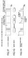
- the optimum value of the heating power Pw1 (heating power of the multi-pulse series) is about 12 mW, the degree of 14T modulation by this power becomes around 65 %, and, thus, the best jitter characteristic is obtained there.
- the light-reception power level of the reflected-light signal RF becomes stable for the portion after the 3T length from the front end during the interval of the above-mentioned detection pulse, this level is sampled by a sample-and-hold circuit, and, an RFsmp value (sampled value of the reflective-light signal RF) is obtained by an A-D converter.
- an RFsmp value sampling value of the reflective-light signal RF
- the RFsmp value were obtained in a case where the power same as the heating power Pw1 optimum for the multi-pulse series were applied in the single pulse, the mark would be formed too much, thereby, the 14T modulation level and the RF light-reception level during the interval of the detection pulse would be saturated as shown in FIG. 3 (right side), and, thus, merely little change would occur in response to change/shift in the heating power.
- the coefficient ⁇ is set so that the ratio of the heating power Pw1 employed for the normal recording operation by the multi-pulse series to the heating power Pw2 employed for the detection pulse which is a single pulse may be fixed.
- trial writing OPC
- the magnitude of the heating power is changed by multiple steps, and recording a mark of small size is performed for each heating power level.
- the value of RFopc obtained in the R-OPC operation is larger than this target value RFopc, the light-emission power of the LD is controlled so as to cause it to be larger.
- the light-emission power of LD is controlled so as to cause it to be smaller. (The reason therefor/logic thereof will be described later.)
- the heating power Pw2 of the detection pulse is controlled so that the recording condition may be obtained such that the target value RFopco may be reached.
- the heating power Pw1 of multi-pulse series can also be appropriately corrected.
- the light-emission power of LD can be controlled based on the mark-formation condition, and' it becomes possible to perform mark formation having a uniform state even when the drive apparatus changes in performance thereof due to aging.
- the coefficient ⁇ to be multiplied to the heating power Pw1 for the multi-pulse series is determined as 0.75.
- a different value may be selected for the coefficient ⁇ according to the pigment material used in the optical disk, setting of the recording line velocity, the multi-pulse width, and so forth.
- the possible variable range of the coefficient ⁇ for various combinations of these factors is preferably a range between 0.6 and 0.9 as a result of study being made, and by choosing the coefficient ⁇ within the range, the high sensitivity recording-condition information value RFopc can be obtained.
- the above-mentioned detection pulse is inserted so as to replace the mark data in recording operation performed basically by the multi-pulse series.
- the length of the single pulse as the detection pulse is made into (n-2)T for the mark length n so that the mark length formed by the single pulse may be equal to that which should be obtained from the original multi-pulse series.
- the length of this single pulse may be determined as being optimum according to the pigment material of the optical disk and the recording line velocity.
- the position of sampling for the detection pulse may be determined in consideration of a time interval for which the level of the reflected-light signal RF is stabilized enough, and, also, the time interval of the sampling may be determined in consideration of the acquisition time of the relevant sampling circuit.
- a time interval to be taken after each sampling may be determined in consideration of aperture delay of the sampling circuit, and, thus, it can be expected that the sampling circuit is realized by an inexpensive configuration and provides a stable operation.
- the detection pulse replaces a multi-pulse series, and, thus, it becomes possible by multiplying with the coefficient so that the heating power Pw2 may become smaller, so as to provide such a heating power of the detection pulse as to obtain the state of the mark formation during recording, properly.
- optical disk apparatus embodying the above information recording system according to the first embodiment of the present invention will now be described.
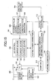
- FIGS. 6 and 7 show block diagrams illustrating a circuit configuration of the optical disk apparatus in the first embodiment of the present invention.
- This optical disk apparatus 1 has a pickup 3 including a an LD (not shown in the figures) which.is a light source for recording information onto an optical disk 2, an EFM pulse encoder 4 which generates recording data, a recording pulse series control part 5 for modulating light emitted from the LD based on the recording data, and an LD control circuit 6 which makes LD emitting light have a desired light-emission waveform based on the recording pulse series control signal which the recording pulse series control part 5 outputs.
- LD not shown in the figures
- the recording pulse series control part 5 generates an LD control signal for driving the LD from the recording data which the EFM pulse encoder 4 outputs.
- This recording pulse series control part 5 includes a recording pulse series generation part 7, and the recording pulse series generation part 7 generates multi-pulse series.
- a detection pulse generation part 8 which generates a detection pulse of a single pulse for the R-OPC operation is also provided in the recording pulse series control part 5, and the detection pulse to be included in the recording pulse series is generated.
- the LD control signal is generated as multi-pulse series including the detection pulse, and the LD control signal is input to the LD control circuit 6.
- the LD control circuit 6 includes LD driving current sources 9, 10 and 11 which act as current sources driving the LD.
- the LD driving current source 9 outputs a heating power for peak level of each pulse of multi-pulse series
- the LD driving current source 10 outputs a heating power for a peak level of the detection pulse for the R-OPC operation
- the LD driving current source 11 outputs a bottom power for a bottom level of each pulse.
- the LD control circuit 6 switches or adds the output of the LD driving current source 9 or 10 and the LD driving current source 11 based on the LD control signal, and outputs the result to the LD, and, thus, produces the LD light-emission waveform (as shown in FIG.
- the recording pulse series generation part 7 and the LD driving current source 9 act as a multi-pulse series generation part, and the detection pulse generation part 8 and the LD driving current source 10 act as a detection pulse generation part.
- a light-receiving device (not shown in the figures) provided in the pickup 3 receives reflected light from the optical disk 2, and outputs a reflected-light signal RF.
- a sampling circuit 13 a sampling-and-holding operation is performed on the reflected-light signal RF at a detection position of a sampling signal, and the detection pulse in a recording pulse series is sampled and undergoes A-D conversion by an A/D converter, not shown in the figure, and, thus, a signal RFsmp showing a sampled level of the luminous energy of reflected light is obtained.
- the level of the reflected light changes according to the luminous energy emitted from the LD. Therefore, the luminous energy level of the reflected light is divided by the heating power for the detection pulse so that it is normalized, and, thus, a recording-condition information value which reflects a state of formation of the record mark formed on the optical disk 2 is calculated by the recording-condition information calculation circuit 23. Namely, the light-emission luminous energy level Pw of the LD is used for the dividing and thus normalization calculation operation is performed by a dividing circuit 25.
- the recording-condition information value RFopc reflecting the state of formation of the record mark is calculated.
- This recording-condition information value RFopc is stored in a RAM or the like of a system controller 12, for example, as a target value RFopco.
- the R-OPC operation is started immediately after starting a normal recording operation, and the recording-condition information value RFopc is calculated as described above at predetermined intervals.
- the heating power Pw2 of the detection pulse is corrected so that it may become smaller.
- the comparator 24 and the first heating power correction circuit 20 act as a first heating power setting part.
- the heating power Pw1 of the normal multi-pulse series should also be corrected by dividing the heating power Pw2 of the detection pulse corrected as mentioned above by the above-mentioned predetermined coefficient ⁇ by a second heating power correction circuit 21.
- the second heating power correction circuit 21 acts as a second heating power setting part.
- the heating power Pw1 for the multi-pulse series and the heating power Pw2 for the detection pulse are well controlled so that the ratio therebetween is kept constant as the predetermined coefficient ⁇ .
- a microcomputer such as the system control 12 may perform functions of part or all of the sampling circuit 13, the recording-condition information operation circuit 23, the heating power correction circuit 19, etc.
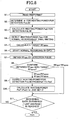
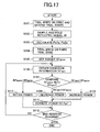
- step S1 pulse width setting information for multi-pulse series and a recommended heating power value are read (in a step S1), the predetermined coefficient ⁇ is determined (in a step S2), and the heating power Pw2 for the detection pulse is calculated (in a step S3), as described above.
- the target value RFopco of the recording-condition information value RFopc is calculated (in a step S5) by detecting the optimum recording power Pwo through the trial writing operation as described above (in a step S4).
- step S6 normal recording
- steps S7 through S10 are performed. That is, a multi-pulse series is replaced by the detection pulse as mentioned above, and the recording-condition information value RFopc is calculated through normalization by the dividing circuit 25 (in a step S7).
- the comparator 24 compares this recording-condition information value RFopc with the target value RFopco (in a step S8).
- the heating power Pw2 of the detection pulse is corrected by the first heating power correcting circuit 20 so as to change it into a power Pw2' (in a step S9), as described above, and, then, a power Pw1' is calculated by dividing the value of Pw2 by the coefficient ⁇ by the second heating power correction circuit 21, and the thus-obtained heating power Pw1' is set for multi-pulse series (in a step S10). Processing of steps S7 through S10 is performed until the end address of recording data is reached (No of the step S11).
- the optical disk apparatus 1 it is possible to configure the optical disk apparatus 1 so that the apparatus 1 can handle either CD-R or DVD-R by selecting either one, as will now be described. That is, normally, in a case of the optical disk apparatus 1 which can carry out recording and reproduction on each of CD family and DVD family, after the optical system and signal processing system of the pickup determine the disk type of the currently loaded disk, they are switched appropriately so that they can properly process the CD family or DVD family according to the determination.
- identification is performed as to whether the currently loaded disk is CD-R or DVD-R (this may be determined by reading the preformat in the above-mentioned step S1). This function corresponds to that of a type detection part. Then, switching is made for the recording pulse series based on the result of this identification determination. That is, when the currently loaded optical disk is a CD-R, single pulse recording scheme is selected, recording is performed by the single pulse recording scheme as shown in FIGS. 4C and 4D, for example, in which a signal pulse is used for forming each record mark. On the other hand, recording is performed by multi-pulse series in which a multi-pulse series is used for forming each record mark, as shown in FIG. 1C, at a time of DVD-R.
- the heating power of the detection pulse when operating R-OPC is appropriately switched. That is, at a time of CD-R, the normal heating power and the heating power of the detection pulse by the single pulse series are made coincident.
- the normal heating power for the multi-pulse series is multiplied by the predetermined coefficient ⁇ , and, thereby, the heating power of the detection pulse may become smaller than the normal heating power for the multi-pulse series.
- a recording layer of the optical disk 2 is such that optical change is caused by thermal decomposition due to laser-light application and/or substrate deformation occurring thereby, and, thereby, a record mark is formed.
- change in luminous'energy of the reflected light has a very high sensitivity, and therefore, this type of disk medium is suitable for the above-described embodiment of the present invention.
- an organic pigment may be used for the recording layer, such as a polymethine pigment, dye of a naphthalocyanine family, a phthalocyanine family, a squalirium family, a croconium family, a pyrylium family, a naphthoquinone family, an anthraquinone family (indanthrene family), a xanthene family, a triphenylmethane family, an azulene family, a tetrahydrocorrin family, a phenanthrene family, a triphenothiazine family, a metal complex compound thereof, etc.
- a polymethine pigment dye of a naphthalocyanine family, a phthalocyanine family, a squalirium family, a croconium family, a pyrylium family, a naphthoquinone family, an anthraquinone family (indanthrene family), a
- These pigments may be mixed or laminated with other organic pigment, metal, metal compound and/or the like for the purpose of improving the optical characteristic, recording sensitivity, signal characteristic, etc., thereof.
- the metals and metal compounds applicable thereto are In, Te, Bi, Se, Sb, Ge, Sn, Al, Be, TeO 2 and SnO, As, Cd, etc. It is also possible to use them in a form of distributed mixture or lamination.
- Formation of the recording layer may be performed by a well-known method, such as vacuum deposition, sputtering, CVD, a solvent application, or the like,
- the above-mentioned dye etc. can be dissolved into an organic solvent, and then, it is applied by a common coating method, such as spraying, roller coating, dipping, spin coating, etc.
- a common coating method such as spraying, roller coating, dipping, spin coating, etc.
- optical disk in the embodiment of the present invention, correction of the recording heating power according to change of performance/characteristic such as defocus, tilt, temperature dependency of LD output, etc. of the driving apparatus can be attained. Thereby, it is possible to perform recording operation in a satisfactory mark formation condition such as to result in non-problematic jitter characteristic throughout the recording area of the disk medium.
- the rate of the optical change during mark formation at the time of recording changes according to the above-mentioned recording material, film thickens of the recording layer, etc.
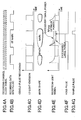
- the luminous energy signal of the reflected light such as that shown in FIG. 9H would be obtained.
- This detection pulse would reflect the luminous energy change occurring according to the condition of mark formation in the same manner as in the above-mentioned R-OPC operation applied to a CD-R system.
- trial writing is performed as preparation work before the R-OPC operation.
- a PCA Power Calibration Area
- 1ECC 16 sectors which is a recording unit.
- the heating power of multi-pulse series is changed by six steps in total, and trial writing is made onto 6 sectors (which zone is referred to as a first trial writing zone).
- the heating power of the detection pulse used in the R-OPC operation is similarly changed by six steps in total, and trial writing is made onto 6 sectors (which zone is referred to as a second trial writing zone).
- the zones of total 12 sectors are used by the trial writing.
- a maximum level Ipk, a minimum level Ibtm, and an average level Idc are detected, as shown in FIG. 12C.
- the modulation degree m2 on the maximum amplitude Imax is calculated from the reproduction signal obtained from the second trial writing zone, by the same methods of level detection and calculation.
- the optimum heating power Pw2o for the detection pulse is calculated from these modulation degrees m1 and m2. For the details of calculation, description will be made later.
- the first trial writing zone and the second trial writing zone can be set adjacent and regarded as one zone, and, thus, recording operation and reproduction operation therefor can be attained by single operation each.
- the modulation degree falls in a range between 0.6 and 0.7 when recording is made by the optimum heating power for DVD-R, using multi-pulse series.
- the modulation degree falls in a range between 0.7 and 0.8, in general.
- the heating power can be used as the optimum heating power such that the modulation degree m2 of the above-mentioned detection pulse should be equal to or larger by approximately 0.1 than the modulation degree m1 obtained from the optimum heating power for the multi-pulse series.
- the heating power which results in the modulation degree predetermined for a particular type of the optical disk or a particular type of the optical disk apparatus from among a plurality of modulation degrees in a range between 0.5 and 0.8 for the detection pulse is previously set as the optimum heating power.
- the optimum heating power Pw2o is calculated for the detection pulse on the modulation degree m2 which is approximately equal to the modulation degree mlo on the above-mentioned optimum heating power for the multi-pulse series, from the modulation degree m2 obtained by the trial writing.
- the detection sensitivity is too small when ⁇ ⁇ 1.0, while, since the heating power is so low that the mark formation is not stabilized yet, and, thus, rather detection error becomes larger, when ⁇ > 2.0. Accordingly, a predetermined heating power such as to provide a predetermined change in modulation degree ⁇ in the range between 1.0 and 2.0 should be used as the optimum heating power.
- the modulation degree m2 of the reproduction signal is obtained and held, and, then, the optimum heating power Pw2o for the detection pulse on the change in modulation degree with respect to the heating power ⁇ 2o obtained from the approximation formula of the modulation degree and heating power which is approximately equal to the above-mentioned change in modulation degree with respect to the heating power ⁇ 1o for the multi-pulse series is calculated.
- the optimum heating power for normal recording by using multi-pulse series and the optimum heating power for the detection pulse for OPC, with a little detection error even due to change in recording condition.
- the objective Pw can be obtained which is the plus solution of the above-mentioned formula.
- the approximated value may likely to have an error from the actual measured value in this case, it is preferable to approximate the modulation degree m, as mentioned above.
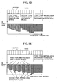
- the trial writing for each of the multi-pulse series and the detection pulse uses total 6 sectors for increasing the heating power by six steps. Further, the first and second trial writing zones are separate completely. However, it is also possible that, as shown in FIG. 14, total 12 sectors are used in which, setting of the recording pulse is switched, and the first and second trial writing operations are performed alternately sector by sector. In this case, also in the reproducing operation, by determining that the first and second trial writing zones are switched alternately sector by sector, it is easy to perform detection operation properly for the first and second trial writing zones. At this time, through the entire area of the first and second trial writing zones, the modulation degree does not change sharply, but approximately increases monotonously. Therefore, it becomes possible to reduce a change amount at a zone at which the heating power is minimum, and the calculation accuracy for each optimum heating power becomes better.
- the above-mentioned PCA of the optical disk includes total 16 sectors, and, 4 sectors are left after the 12 sectors are used as mentioned above as the first and second trial writing zones, as shown in FIG. 14, and, these 4 sectors are used for a third trial writing zone for setting the target value RFopco of the recording-condition information used for the actual R-OPC operation, as shown in FIGS. 12B, 13 and 14.
- the second optimum heating power Pw2o for the detection pulse is obtained from the reflected-light signal RF obtained from the first and second trial writing zones, and, this heating power is used for performing trial writing on this third writing zone.
- the target value RFopco is obtained.
- the third trial writing zone of 4 sectors are located adjacent to the first and second trial writing zones, and total 16 sectors are used for the trial writing as a whole. Since the purpose of this third trial writing is to perform detection of mark-formation condition during actual recording operation properly, the third trial writing may be performed by basically multi-pulse series, and, the multi-pulse series is replaced by the detection pulse according to a frequency of performance of the detection.
- all the recording pulses may include only the detection pulses, results of many times of detection by sampling, which will be described later, are held, and the average thereof is obtained, thereby the accuracy of the detection level and target value of the recording-condition information being able to be improved.
- actual trial writing operation is performed such that, subsequent to recording on the first trial writing zone by using multi-pulse series, recording on the second trial writing is performed by using multi-pulse series but partially replaced by the detection pulse adjacently. Then, reproduction operation can be performed on the first and second trial writing zones collectively at once. Therefore, one trial writing operation can be performed within a short time, needing only a small-sized zone on the optical disk, in which highly precise trial writing for multi-pulse series and the detection pulse can be performed.
- the recording pulse series which contain the detection pulse are used for performing recording on the third trial writing zone, subsequently, adjacent to the first and second trial writing zones.
- FIGS. 15 and 16 are block diagrams showing a general configuration of the optical disk apparatus in the second embodiment of the present invention.
- the circuit configuration shown in FIG. 15 is the same as that shown in FIG. 6 of the first embodiment, and the duplicated description thereof is omitted.
- the maximum level Ipk is held by a peak hold circuit 114 of the sampling circuit 113, the minimum level Ibtm is held by the bottom hold circuit 115, and, then, the average level Idc obtained through a high-frequency region removal process by a low-pass filter 116 is detected.
- These signals are sampled by a second sample-and-hold circuit 118 at predetermined detection positions so as to provide sampled signals, respectively, and, the thus-obtained sampled levels are converted into a digital signal by an A-D converter (not shown in the figure).
- a first power calculation circuit 120 and a second power calculation circuit 121 calculate the optimum heating power Pw1o for the multi-pulse series and the optimum heating power Pw2o for the detection pulses by the above-described processes.
- trial writing is performed on the third trial writing zone by the heating power Pw2o calculated by the second power calculation circuit 121.
- the reflected light from the optical disk 102 obtained during the recording operation is received by the light-receiving device, not shown in the figure, and, the thus-obtained detection signal is sampled and held by the sampling circuit 113 as described above.
- the signal RFsmp obtained at the time is normalized as a result of being divided by the light-emission luminous energy level Pw2 through a dividing circuit 125 of a recording-condition information calculation circuit 123, and, thus, a recording-condition information value RFopc which reflects the mark formation condition is calculated.
- This recording-condition information value RFopc obtained during the trial writing is stored in a RAM of the system controller 112, or the like, as a target value RFopco.
- a comparator 124 compares the magnitude of this target value RFopco with the recording-condition information value RFopc obtained at predetermined intervals as described above.
- the second power calculation circuit 121 calculates the optimum heating power Pw2o for the detection pulse according to the result of this comparison each time.
- a heating power correction circuit 122 outputs the optimum heating power Pw1o or Pw2o calculated by the first power calculation circuit 120 and the second power calculation circuit 121 to an LD driving current source 109 or 110, and the LD driving current sources 109 or 110 performs control such that the LD emits the optimum heating power Pw1o or Pw2o.
- trial writing is performed onto the first and second trial writing zones as described above (in a step S101). Then, sampling and holding of the reflected-light signal RF on this recording is carried out as described above by the sampling circuit 113 (in a step S102). Then, the optimum heating powers Pw10 and Pw2o are calculated by the first and second power calculation circuits 120 and 121 by using the data sampled and held as mentioned above (in a step S103). Then, trial writing is performed onto the third trial writing zone by the thus-obtained heating power Pw2o (in a step S104).
- the recording-condition information value RFopco is obtained as described above from the results of the above-mentioned recording, this value is set as the target value RFopco (in a step S105), and thus, a series of trial writing is ended.
- the steps S101 through S105 is a trial writing process as a whole, and the step S105 is a target value acquisition process.
- the R-OPC operation is started after starting of the normal recording onto the optical disk 102, and, then, the recording-condition information value RFopc is obtained as described above at predetermined intervals (in a step S106).
- the comparator 124 compares the target value RFopco with the current recording-condition information value RFopc each time (in a step S107).
- the heating powers can be always kept as the.optimum ones even when various change in performance of the driving apparatus due to aging or the like occurs. Thereby, it is possible to attain recording on the optical disk 102 with uniform and low jitter
- the recordable optical disk 102 such as a DVD-R, or the like has a recording management area (RMA) to which recording management data (RMD) obtained by the trial writing is recorded, other than the trial writing area (PCA).
- RMA recording management area
- This RMD recorded onto the RMA can have various information concerning recording written thereto, such as disk ID, drive ID, a recording strategy setting, record date/time, address of trial writing, optimum heating power, etc.
- the optimum heating power for multi-pulse series and the optimum heating power for the detection pulse obtained by the above trial writing are made to be written in as information of the RMA.
- the position thereof to be used for this purpose may be a part of a predetermined area prepared for drive ID data such as serial number and/or model number of the driving apparatus, or an area for reserved data to be newly allocated therefor.
- the above-mentioned information concerning R-OPC may be written there such that, the optical disk 102 on which the trial writing has been performed and the specific optical disk apparatus 101 are determined, and, thereby, the specific combination can be identified from the thus-written information.
- the ratio of the optimum heating power for multi-pulse series and the optimum heating power for the detection pulse calculated from the data obtained by trial writing, Pw2o/Pwlo may be written there.
- the optical disk apparatus 101 recognizes the optical disk 102, and reads the latest recording management information written in the RMA concerning the results of the trial writing performed in the past, as preparation for actual recording. From this record management information, the information to be used for R-OPC operation is selected written in a previously allocated position. Then, the optical disk apparatus 101 determines as to whether or not the information concerning the R-OPC operation has been written in the optical disk 102 by the same optical disk apparatus 101 in the past. When it has not been written in the past, the above-mentioned trial writing can newly be performed, thereby, the optimum powers for multi-pulse series and the detection pulse and the recording-condition information value are obtained, and, thereby, the R-OPC operation can be performed.
- the ratio Pw2o/Pw1o which is calculated from the optimum powers for multi-pulse series and detection pulse'read therefrom, or the ratio of the optimum heating powers Pw20/Pw10 read therefrom is held in a RAM, or the like of the system controller 112.
- Trial writing to be newly performed in this case is only such that, thereby, the optimum heating power for multi-pulse series is obtained, and then, the optimum heating power for the detection pulse can be calculated by carrying out the multiplication of the ratio of the optimum heating powers held in the RAM or the like.
- FIGS. 19A through 19F different from the above-described second embodiment described with reference to FIGS. 12A through 12F, 8 sectors of the PCA are used for the first trial writing for multi-pulse series, the other 8 sectors thereof are used for the second trial writing for the detection pulse, and no third trial writing is performed.
- the other configuration and operation of the trial writing of the third embodiment are the same as those of the second embodiment, and duplicated description thereof is omitted.
- the block configuration of an optical disk apparatus 201 in the third embodiment of the present invention is the same as that of the above-described second embodiment described with reference FIGS. 15 and 16.
- the operation of the third embodiment is the same as that of the second embodiment described above with reference to FIG. 17, except that, in the third embodiment, the third trial witting is omitted as mentioned above, each of the first and second trial writing zones includes 8 sectors as mentioned above, and the target value RFopco is obtained through trial writing made onto the first and second trial writing zones.
- the other configuration and operation of the third embodiment is the same'as those of the second embodiment, and duplicated description thereof is omitted.
- a record mark corresponding to each mark data length nT (n denotes an integer in a range between 3 and 14, and T denotes a recording clock period) is formed by a plurality of heating pulses (multi-pulse series) for the pigment-recording-layer type (pigment-type) optical disk.
- the number of pulses, n-x (x is 1 or 2), and the ratio of the pulse width of the top pulse to the recording clock period, Ttop, the ratio of the pulse width of the subsequent pulses to the recording clock period, Tmp, and the ratio of the pulse width of the last pulse to the recording clock period, Ttail are determined.
- the condition of mark formation is strongly affected by the recording line velocity Lv and thus has a strong correlation therewith.
- setting is made in detail for the above-mentioned ratio Ttop of the head heating pulse width to the recording clock period T, the ratio Ttail of the pulse width of the last heating pulse to the recording clock period T, and the above-mentioned ratio ⁇ of the recording powers, according to the recording line velocity. Especially, finely correction is made on the recording power (heating power).
- the recording line velocity at the most inner zone of the disk is approximately 3.5 m/s, and is approximately 8.5 m/s for the most outer zone.
- the recording clock frequency is approximately 63.7 MHz for the most outer zone, and is approximately 26.2 MHz for the most inner zone of the disk. Thereby, difference in the recording line velocity is approximately 2.4 times therebetween.
- the fourth embodiment of the present invention it becomes possible to attain recording by record marks having uniform signal characteristic and low jitter throughout the disk medium in the range between the most inner zone and the most outer zone.
- setting is made for the most inner zone such that: the number of heating pulses of the recording pulse series is n-1 (n denotes a mark data length); the ratio Ttop of the pulse width of the head heating pulse is 1.30 T, each of the ratio Tmp of the pulse width of each subsequent intermediate pulse and the ratio Ttail of the pulse width of the tail heating pulse is 0.65 T, and the optimum recording power Pwmin (or Pmin) of the heating pulse is 9.0 mW.
- These setting values are typical numerical values for a pigment-type disk medium, and, may be changed depending on various tuning and/or recording material thereof.
- the ratio ⁇ is changed by 0.50 according to the radial position corresponding to the increase in recording line velocity so that it may become larger.
- FIGS. 25A, 25B and 25C comparatively show light-emission waveforms of the thus-set recording pulses at the most inner zone and most outer zone together in such a time scale that the periods of the recording channel clock pulses are caused to be equal to one another.
- the recording power is approximately proportional to the squire root of the recording line velocity, as well known, for example, see Japanese Laid-Open Patent Application No. 10-106008 mentioned above.
- a combination of the recording pulse series according to the CAV recording control scheme is not limited to the above-described one.
- the basic concept of the fourth embodiment of the present invention may be applied to a case where, as being applied for CD-R disk, the front edge position and rear edge position of a single rectangle wave pulse which is not a multi-pulse series but a head portion is emphasized are corrected according to a mark length, a case where, as being applied for DVD-R disk, both the edge positions at the front and rear of the head heating pulse are corrected, and so forth.
- the setting may be finely optimized with respect to the recording line velocity in a similar manner.
- the front edge position of the head heating pulse and the rear edge position of the tail heating pulse are made to be changed as described above as shown in FIG. 25C, and, thereby, control can be simplified.
- recording is made on the trial writing zone provided at the most inner position of the optical disk medium while the recording power is changed by a plurality steps, as in the previously described embodiments, and an optimum recording power is determined such that the characteristic values obtained from the respective reproduction signals may have satisfactory values.
- trial writing at the maximum recording line velocity can also be performed, and thereby, a basic approximation formula for the recording power with respect to the entire zone of the optical disk according to the CAV recording scheme may be calculated.
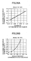
- 'asymmetry' is a value obtained through normalization of a difference between the average level on the longest data amplitude of the RF signal and the average level on the shortest data amplitude thereof by the longest data amplitude, and shows the asymmetry between the mark length and space length.
- Mod. is a value obtained through normalization of the longest data amplitude of the RF signal by the maximum level on the longest data, and shows a relative ratio of reflectance difference between the mark and space on the maximum length data.
- Modulation I 14 ⁇ H - I 14 ⁇ L I 14 ⁇ H where I 14H denotes a 14T space level, and I 14L denotes a 14T mark level.
- a ⁇ method may be used in many cases in which a recording power Pt such that an inclination ⁇ t of a target Mod. change may be obtained is multiplied by a constant ⁇ t, and, thus, the optimum recording power is obtained.
- a recording power Pt such that an inclination ⁇ t of a target Mod. change may be obtained is multiplied by a constant ⁇ t, and, thus, the optimum recording power is obtained.
- description thereof is omitted.
- all the other drawings illustrating the fourth embodiment illustrate the pigment-type optical disk.
- a groove for acquiring a tracking error signal is formed onto a recording disk such CD or DVD, and a wobble signal is recorded by bending the groove in a zigzag manner.
- This wobble signal is detected by a programmable BPF for various recording line velocities, and, therefrom, coded information such as that coded by frequency modulation or phase modulation is restored. Accordingly, even from a non-recorded disk, address information and disk information unique to the disk can be obtained.
- a method by which the above-mentioned information may be generated from a slit-like intermittent pit formed in a land (LPP: Land-Prepit signal) is also known.
- a wobble scheme by a phase modulation in DVD it is possible to set the frequency thereof to very high, and, with regard to the scheme by LPP, it is possible to demodulate from a signal formed into a minute figure equivalent to a data length. Accordingly, highly precise position detection is possible with respect to pre-addresses given to the disk. Therefore, it becomes possible to connect and record on the terminus part of a last record at an accuracy of approximately ⁇ 5T by detecting and demodulating this preformat information, even in case where record data is added to follow the last record, or interrupting record and resuming is performed.
- a recording clock signal is generated by PLL with reproduction of the already recorded immediately preceding data, and also, a recording clock signal is generated from the wobble signal, thereby, the clock signal to be used beings switched at a time the target address is reached from the already reached data.
- the information recording method in this fourth embodiment of the present invention will now be described with reference to FIG. 29.
- the above-described recommended setting values of the recording pulse widths for a plurality of recording line velocities including the minimum (most inner) recording line velocity and the maximum (most outer) recording line velocity, and intermediate recording line velocity, and the recommended setting values of the recording powers or the ratio ⁇ max of the recording powers (the ratio ⁇ in recording power between those for the inner and outer zones) are read from the preformat information of the optical disk medium 401 (in a step S401).
- the optimum recording powers are newly reset by using the result of trial writing (OPC) on the minimum (most inner) recording line velocity and the maximum (most outer) recording line velocity by the information record apparatus 401 (S402).
- the basic approximation formula (first approximation formula) for respective pulse widths and recording powers with respect to the recording line velocities for the entire recording area of the optical disk medium 401 is derived so that the setting values may be calculated (S403).
- the recording area of the recording medium 401 is divided as shown in FIG. 28 corresponding to the data amount to be recorded, and, an address range for each recording zone is calculated individually (S404).
- an interval of updating the pulse width and recording power setting values for a first recording zone (most inner first recording zone), and an address range corresponding thereto are determined, and, then, the pulse width and recording power setting values for the first recording zone are calculated for updating (S406).
- the current address is read from the preformat information (S407), and it is determined whether or not the read address is within a range in which the setting value is retained (S408).
- the newly calculated setting values are used for updating the current values (S406 and S407). Thereby, it is possible to perform recording continuously across different recording zones.
- the current address is within the range (Y of S408), the recording is performed by CAV control as described above. The same processing is repeated until the end address of the current recording zone is reached (S409).
- the characteristic value of the reproduction signal is detected for each recording zone, and recording is performed with correction of the approximation formula.
- the approximation formula for setting the recording power should be calculated according to characteristics of the optical disk medium 401 as described above, and, for this purpose, another manner, for example, linear approximation, or another polynominal approximation formula may also be used.
- the approximation formula thus obtained for the setting values are used according to the relevant recording line velocity. Therefore, the relevant recording line velocity should be determined from the address information obtained from demodulation of the above-mentioned wobble signal or LPP signal. In fact, specific addresses are predetermined for the range between the most inner position and most outer position, and have correspondences with the recording line velocities to be used.
- a servomechanism 405 is connected to an objective lens driving device and an output system of the optical head 404.
- a reproduction signal detection part 406 performing reproduction operation, calculating the modulation degrees or asymmetries and so forth from the reproduction signal detected by the light-receiving device of the optical head 404 is provided.
- a wobble detection part 408 containing a programmable BPF 407 is connected to the servomechanism 405 and the reproduction signal detection part 406.
- An address demodulation circuit 409 which demodulates addresses from the detected wobble signal is connected to the wobble detection part 408.
- a PLL synthesizer circuit 410 is provided in a recording clock generation part 411 which is connected with the address demodulation circuit 409.
- a drive controller 412 is connected to the PLL synthesizer circuit 410.
- the rotation mechanism 403, servomechanism 405, the reproduction signal detection part 406, the wobble detection part 408, and the address demodulation circuit 409 are also connected to this drive controller 412 which is connected to the system controller 413.
- a system controller 413 has a recording power calculation part 414, and, is connected to an EFM encoder 415, and to an LD controlling part 416 acting as a laser light source controlling part.
- This LD control part 416 contains an edge signal generation part 418 described later besides a recording pulse series generation part 417 which generates a heating multi-pulse control signal containing the above-mentioned head heating pulse and tail heating pulse.
- An LD drive part 420 which is a driver circuit as a laser light source drive part to make the semiconductor laser in the optical head 4 drive by switching respective sources 419 of driving currents for the recording power Pw and bias power Pb is connected to the output side of LD control part 416.
- the central frequency of the BPF 407 corresponding to the recording line velocity is set to the programmable BPF 407 by the drive controller 412. Then, while carrying out address demodulation by the address demodulation circuit 409 from the wobble signal detected by the wobble detection part 408, the recording channel clock signal for each recording line velocity is generated by the PLL synthesizer circuit 410 having the basic clock frequency thereof changed by the drive controller 412, and it is provided to the recording pulse series generation part 417.
- the recording channel clock signal and the EFM data which is record information are respectively input into the recording pulse series generation part 417 from the recording clock generation part 411 and the EFM encoder 415, and the recording pulse control signals for the recording pulses which contain the head heating pulse, tail heating pulse, and intermediate heating multi-pulse series are generated by the recording pulse series generation part 417.
- the respective sources 419 of driving currents for the recording power Pw and the bias power Pb are appropriately switched by the LD drive part 420.
- the semiconductor laser is made to emit light by the bias power Pb corresponding to reproduction power constantly by the source of bias current at a time of recording, and, a laser light-emission waveform of the recording pulses as shown in FIG. 23C is provided from the recording pulse control signal generated in the above-mentioned recording pulse series generation part 417.
- a multi-stage delay circuit having a delay amount of approximately 0.5 ns employing gate devices is provided.
- the recording pulse control signal front edge signal
- the recording pulse control signal rear edge signal
- the recording pulse control signal rear edge signal
- Such a configuration determines each setting value as described above, the optimum edge pulse is selected for a relevant recording line velocity, and thus, the proper recording pulse is generated.
- each setting value changes as shown in FIG. 24.
- each pulse width is fixed, and, as the recording channel clock signal changes, the ratio of the pulse widths and duty are changed accordingly.
- a pulse edge generation part having a PLL configuration emptying a phase comparator, a loop filter, a VCO (voltage controlled oscillator), and a frequency divider may be used.
- the frequency of the recording channel clock signal is multiplied by 20
- the thus-obtained high-resolution clock signal is generated by the PLL, and, thus, the pulse edge signal has a resolution of 0.05T, i.e., approximately in a range between 1.9 ns and 0.8 ns.
- this multi-stage pulse edge signal is input into an edge selector having a multiplexer configuration, the front edge signal which controls the front edge position of the head heating pulse by the edge pulse selected by the system controller 413 is generated.
- a pulse edge generation part of a PLL configuration is provided in an edge pulse generation circuit of the edge signal generation part 418 which controls the rear edge position of the tail heating pulse.
- the rear edge signal which controls the rear edge position of the tail heating pulse is generated by the edge pulse selected by the system controller 413.
- each setting value is determined as described above, the optimum edge pulse is selected for each recording line velocity, and thus, a desired recording pulse is generated.
- each setting value changes stepwise in a sawteeth manner.
- each of the ratios of the pulse widths Ttop and Ttail are fixed even the recording clock signal changes in frequency changes during an interval between successive updating.
- the fourth embodiment of the present invention for any of these configurations, uniform recording is possible at a time of CAV recording, and various circuit configurations may be used for the recording pulse generation part.
- recording according to CAV control including updating of setting values of the ratio of pulse width of the head heating pulse Ttop, the ratio of the pulse width of the tail heating pulse Ttail, and the recording power ratio ⁇ can be performed, by a simple and small-scale circuit configuration.
- reproduction signal detection part 406 connected to the optical head 404 detects the.3T and 14T mark and space levels of the. RF signal, and the asymmetry or the degrees of modulation (Modulation), and the approximation formulas thereof are calculated by the system controller 413. Then, the system controller 413 calculates the basic approximation formula (first approximation formula) for each pulse width and recording power for the recording line velocity, divides the recording area into a plurality of recording zones according to data amounts to be recorded, and calculates address ranges for the respective recording zones individually.
- the interval of updating the pulse width and recording power setting values for the first recording zone (the most inner recording zone), and the corresponding address range are allocated, and the pulse widths and recording powers are calculated for the updating interval in the first recording zone.
- the address demodulation circuit 409 While performing recording according to CAV control, the address demodulation circuit 409 reads the.current address from the preformat information of the disk 401, and, it is determined whether or not it is within the range of updating the setting values, i.e., the address range, by the system controller 413. When the current address is out of the updating range, the newly calculated setting values are set, and recording is performed continuously.
- recording operation is once interrupted under control by the system controller 413.
- a tracking servo unit contained in the servomechanism 405 the last track of the recording-finished recording zone is jumped back to, and reproduction is performed thereon.
- detection of the asymmetry or the modulation degree (Modulation) is performed by the reproduction signal detection part 406.
- the recording power calculating part 414 of the system controller 413 from the recording-power dependency (through the above-described Asy or Mod approximation formula) in the OPC, a difference from the optimum recording power ⁇ Pw is calculated.
- the amount of ⁇ Pw the basic approximation formula for setting the recording power is corrected for the subsequent recording zone.
- This computer 421 includes an DVD-R drive 423 besides a 3.5-inch-type FD drive 422 built therein.
- the DVD-R drive 423 acts as the information recording apparatus according to the above-described relevant embodiment of the present invention.
- the information recording apparatus 423 is built in the personal computer 421, when information is recorded into an optical disk medium by using the recording pulse series which includes the head heating pulse and successive heating pulses containing the tail heating pulse, while the optical disk medium is rotated, it is possible to perform recording onto the optical disk medium with signal characteristic uniform throughout the recording area thereof according to the CAV manner, while the compatibility with the conventional recording format for media only for reproduction is maintained, without performing variable velocity control of the rotation speed of the optical disk medium.
- the optical disk medium may be divided concentrically into a plurality of recording zones in consideration of difference between the data transfer rate from the personal computer body 421 to the information recording apparatus 423 and the data recording rate of the information recording apparatus 423 itself, and thus, control should be made such that recording operation is interrupted and resumed across the thus-divided different recording zones. Even in such a case, throughout all over the optical disk medium, recording with uniform signal characteristic can be performed, and, thus, the information recording apparatus 423 can be effectively used together with the personal computer body 421.
Landscapes
- Physics & Mathematics (AREA)
- Optics & Photonics (AREA)
- Optical Recording Or Reproduction (AREA)
- Optical Head (AREA)
Applications Claiming Priority (5)
| Application Number | Priority Date | Filing Date | Title |
|---|---|---|---|
| JP2000348777A JP4046468B2 (ja) | 2000-11-15 | 2000-11-15 | 光ディスク装置及び光ディスク |
| JP2000360017A JP4514940B2 (ja) | 2000-11-27 | 2000-11-27 | 光ディスク装置 |
| JP2000362367A JP2002170236A (ja) | 2000-11-29 | 2000-11-29 | 光ディスク装置及び光ディスクの記録方法 |
| JP2001003409A JP2002208139A (ja) | 2001-01-11 | 2001-01-11 | 情報記録方法、情報記録装置及び情報処理装置 |
| EP01309608A EP1207525B1 (de) | 2000-11-15 | 2001-11-14 | Optisches Informationsaufzeichnungsverfahren mit einem verbesserten Schema zur Aufzeichnungsleistungssteuerung |
Related Parent Applications (1)
| Application Number | Title | Priority Date | Filing Date |
|---|---|---|---|
| EP01309608A Division EP1207525B1 (de) | 2000-11-15 | 2001-11-14 | Optisches Informationsaufzeichnungsverfahren mit einem verbesserten Schema zur Aufzeichnungsleistungssteuerung |
Publications (2)
| Publication Number | Publication Date |
|---|---|
| EP1860654A1 true EP1860654A1 (de) | 2007-11-28 |
| EP1860654B1 EP1860654B1 (de) | 2009-03-04 |
Family
ID=27481778
Family Applications (2)
| Application Number | Title | Priority Date | Filing Date |
|---|---|---|---|
| EP07017459A Expired - Lifetime EP1860654B1 (de) | 2000-11-15 | 2001-11-14 | Optisches Informationsaufzeichnungsverfahren mit einem verbesserten Schema zur Aufzeichnungsleistungssteuerung |
| EP01309608A Expired - Lifetime EP1207525B1 (de) | 2000-11-15 | 2001-11-14 | Optisches Informationsaufzeichnungsverfahren mit einem verbesserten Schema zur Aufzeichnungsleistungssteuerung |
Family Applications After (1)
| Application Number | Title | Priority Date | Filing Date |
|---|---|---|---|
| EP01309608A Expired - Lifetime EP1207525B1 (de) | 2000-11-15 | 2001-11-14 | Optisches Informationsaufzeichnungsverfahren mit einem verbesserten Schema zur Aufzeichnungsleistungssteuerung |
Country Status (3)
| Country | Link |
|---|---|
| US (3) | US6664526B2 (de) |
| EP (2) | EP1860654B1 (de) |
| DE (1) | DE60137877D1 (de) |
Families Citing this family (52)
| Publication number | Priority date | Publication date | Assignee | Title |
|---|---|---|---|---|
| US6664526B2 (en) * | 2000-11-15 | 2003-12-16 | Ricoh Company, Ltd. | Optical information recording employing improved recording power control scheme |
| US7242651B2 (en) * | 2000-12-11 | 2007-07-10 | Sanyo Electric Co., Ltd. | Disk reproduction device |
| US6950377B2 (en) * | 2001-06-26 | 2005-09-27 | Matsushita Electric Industial Co., Ltd. | Information recording method and information recording apparatus |
| JP3812378B2 (ja) * | 2001-07-12 | 2006-08-23 | ティアック株式会社 | 光ディスク装置 |
| CN1828743A (zh) * | 2001-09-06 | 2006-09-06 | 皇家飞利浦电子股份有限公司 | 运行最优功率控制的设备 |
| JP2003178451A (ja) * | 2001-12-11 | 2003-06-27 | Yamaha Corp | 光ディスク記録方法及び光ディスク記録装置 |
| JP3521141B2 (ja) * | 2002-01-08 | 2004-04-19 | 株式会社リコー | 情報記録装置 |
| JP2003317251A (ja) * | 2002-02-21 | 2003-11-07 | Ricoh Co Ltd | 光ディスク装置、光記録方法、光記録プログラムおよび記憶媒体 |
| KR20040009454A (ko) * | 2002-07-23 | 2004-01-31 | 삼성전자주식회사 | 광정보 저장매체 및 그 기록방법 |
| JP2004110915A (ja) * | 2002-09-17 | 2004-04-08 | Ricoh Co Ltd | ライトパワー制御方法およびその装置 |
| US7197062B2 (en) * | 2002-10-01 | 2007-03-27 | Intel Corporation | Method and apparatus to detect and decode information |
| EP1783754B1 (de) * | 2002-10-10 | 2008-10-01 | Matsushita Electric Industrial Co., Ltd. | Optisches Datenaufzeichnungsmedium |
| KR100498449B1 (ko) * | 2002-10-14 | 2005-07-01 | 삼성전자주식회사 | 광 디스크 시스템에서 기록 가능한 광 디스크에 대한 기록파워 결정 방법 |
| US20040130993A1 (en) * | 2003-01-02 | 2004-07-08 | Nedi Nadershahi | Method and apparatus for a high speed write strategy |
| JP2004220663A (ja) * | 2003-01-10 | 2004-08-05 | Pioneer Electronic Corp | 光ピックアップ装置、光ビーム出射制御方法、並びに、光ビーム出射制御プログラムおよびそれを記録した記録媒体 |
| JP4209205B2 (ja) * | 2003-01-10 | 2009-01-14 | パイオニア株式会社 | 光ビーム出力制御装置、光ピックアップ装置、光ビーム出射制御方法、並びに、光ビーム出射制御プログラムおよびそれを記録した記録媒体 |
| TWI304973B (en) * | 2003-01-23 | 2009-01-01 | Lg Electronics Inc | Recording medium with copy protection information formed in intermittent or alternate wobbled pits and apparatus and methods for forming, recording, and reproducing the recording medium |
| EP1586087B1 (de) * | 2003-01-23 | 2013-08-21 | LG Electronics, Inc. | Aufzeichnungsmedium mit optionaler information, verfahren zur bildung des aufzeichnungsmediums, und vorrichtung und verfahren zur wiedergabe des aufzeichnungsmediums |
| KR100952949B1 (ko) | 2003-01-24 | 2010-04-15 | 엘지전자 주식회사 | 고밀도 광디스크의 복사 방지 정보 관리방법 |
| JP2004234699A (ja) * | 2003-01-28 | 2004-08-19 | Hitachi Ltd | 光ディスクの記録波形制御方法およびこれを用いた光ディスク装置 |
| KR100750109B1 (ko) * | 2003-02-15 | 2007-08-21 | 삼성전자주식회사 | 정보 저장매체 |
| EP1625572B1 (de) * | 2003-05-09 | 2009-12-09 | Koninklijke Philips Electronics N.V. | Verfahren und vorrichtung zur ermittlung eines optimalen leistungspegels |
| ATE535908T1 (de) * | 2003-05-28 | 2011-12-15 | Koninkl Philips Electronics Nv | Optisches datenspeichermedium mit mehreren aufzeichnungsschichten |
| JP2007527081A (ja) * | 2003-07-07 | 2007-09-20 | エルジー エレクトロニクス インコーポレーテッド | 記録媒体、記録媒体上への制御情報の構成方法及びこれを用いたデータの記録再生方法と記録再生装置 |
| KR100953637B1 (ko) * | 2003-07-07 | 2010-04-20 | 엘지전자 주식회사 | 광디스크 및 광디스크의 디스크정보 기록방법 |
| CA2474995C (en) * | 2003-07-07 | 2011-11-22 | Lg Electronics Inc. | Recording medium, method of configuring control information thereof, recording and/or reproducing method using the same, and apparatus thereof |
| US7564760B2 (en) * | 2003-07-09 | 2009-07-21 | Lg Electronics, Inc. | Recording medium, method of configuring disc control information thereof, recording and reproducing method using the same, and apparatus thereof |
| JP4602648B2 (ja) * | 2003-07-15 | 2010-12-22 | 株式会社リコー | 情報記録方法及び情報記録装置 |
| DE602004024079D1 (de) | 2003-08-14 | 2009-12-24 | Lg Electronics Inc | Aufzeichnungsmedium, verfahren zur konfiguration von steuerinformationen dafür, aufzeichnungs- und wiedergabeverfahren damit und vorrichtung dafür |
| KR101024904B1 (ko) * | 2003-08-14 | 2011-03-31 | 엘지전자 주식회사 | 기록매체, 기록방법, 기록장치 및 기록재생시스템 |
| ATE532178T1 (de) * | 2003-08-14 | 2011-11-15 | Lg Electronics Inc | Aufzeichnungsmedium, verfahren zum konfigurieren von steuerinformationen dafür, aufzeichnungs- und wiedergabeverfahren damit und vorrichtung dafür |
| ATE428173T1 (de) * | 2003-08-14 | 2009-04-15 | Lg Electronics Inc | Aufzeichnungsmedium, verfahren zur konfiguration von steuerinformationen dafur, aufzeichnungs- /wiedergabeverfahren damit und vorrichtung dafur |
| TW200540831A (en) * | 2004-03-15 | 2005-12-16 | Matsushita Electric Industrial Co Ltd | Optical information recording method, optical information recording apparatus, and optical information recording medium |
| JP3970255B2 (ja) * | 2004-03-25 | 2007-09-05 | 三洋電機株式会社 | 光ディスク装置 |
| JP3907639B2 (ja) * | 2004-05-10 | 2007-04-18 | 三菱電機株式会社 | 光記録方法及び光記録装置 |
| US7706230B2 (en) * | 2004-05-13 | 2010-04-27 | Lg Electronics, Inc. | Recording medium, read/write method thereof and read/write apparatus thereof |
| JP2006012226A (ja) * | 2004-06-23 | 2006-01-12 | Hitachi Ltd | 記録方法及び光ディスク装置 |
| KR101041809B1 (ko) * | 2004-07-27 | 2011-06-17 | 엘지전자 주식회사 | 광디스크 및 광디스크 제어정보 구성방법 및 이를 이용한광디스크 기록재생방법과 장치 |
| JP2006092664A (ja) * | 2004-09-24 | 2006-04-06 | Ricoh Co Ltd | 光情報記録装置 |
| JP4418374B2 (ja) * | 2005-01-25 | 2010-02-17 | 株式会社日立エルジーデータストレージ | 光ディスクの信号記録方法および光ディスク装置 |
| JP4395450B2 (ja) * | 2005-02-08 | 2010-01-06 | 太陽誘電株式会社 | 光情報記録装置および信号処理回路 |
| JP2006236540A (ja) * | 2005-02-28 | 2006-09-07 | Funai Electric Co Ltd | ハードディスク付き光ディスク記録再生装置 |
| JP2006252676A (ja) * | 2005-03-10 | 2006-09-21 | Ricoh Co Ltd | 情報記録再生装置 |
| WO2007007319A1 (en) * | 2005-07-07 | 2007-01-18 | Mempile Inc. | Method and system for data recording and reading in multi-photon excitable media |
| JP4238854B2 (ja) * | 2005-07-27 | 2009-03-18 | ソニー株式会社 | 光ディスク駆動装置及び信号記録方法 |
| US8279733B2 (en) * | 2005-08-31 | 2012-10-02 | Mediatek Inc. | Dynamic write strategy modification method and apparatus |
| WO2007038634A2 (en) * | 2005-09-26 | 2007-04-05 | Silicon Core Technology, Inc. | Enhanced linearity dvd writing current circuit |
| JP2007213680A (ja) * | 2006-02-08 | 2007-08-23 | Toshiba Corp | 自動パワー制御フィルタ回路および光ディスク装置 |
| JP4560009B2 (ja) * | 2006-05-31 | 2010-10-13 | 株式会社東芝 | 光記録媒体、情報記録方法、および情報再生方法 |
| JP2010044807A (ja) * | 2008-08-08 | 2010-02-25 | Hitachi-Lg Data Storage Inc | 記録パワーの調整方法及び光ディスク装置 |
| US9034233B2 (en) | 2010-11-30 | 2015-05-19 | Infineon Technologies Ag | Method of processing a substrate |
| US9103725B2 (en) * | 2012-02-08 | 2015-08-11 | Finisar Corporation | System and method of electromagnetic radiation control |
Citations (2)
| Publication number | Priority date | Publication date | Assignee | Title |
|---|---|---|---|---|
| EP0414557A2 (de) | 1989-08-25 | 1991-02-27 | Sharp Kabushiki Kaisha | Aufnahme-/Wiedergabegerät für optische Scheibe |
| EP0712120A1 (de) * | 1994-05-31 | 1996-05-15 | Sony Corporation | Datenregistriergerät |
Family Cites Families (16)
| Publication number | Priority date | Publication date | Assignee | Title |
|---|---|---|---|---|
| JPS54143109A (en) | 1978-04-28 | 1979-11-08 | Hitachi Ltd | Optical information device |
| JPS5760696A (en) | 1980-09-27 | 1982-04-12 | Mitsubishi Electric Corp | Microwave discharge light source |
| JPS5792438A (en) | 1980-11-28 | 1982-06-09 | Ricoh Co Ltd | Recording method by laser beam |
| JPH0213372A (ja) | 1988-06-30 | 1990-01-17 | Takeda Chem Ind Ltd | スーパーオキサイド・ジスムターゼの精製法 |
| JP3034268B2 (ja) * | 1990-02-19 | 2000-04-17 | 株式会社日立製作所 | ディスク状記録媒体および記録/再生装置 |
| US5825733A (en) * | 1990-07-31 | 1998-10-20 | Sony Corporation | Optical disc recording apparatus for recording data at a disc rotational speed selected from a range of disc rotational speeds |
| JP3039099B2 (ja) | 1992-02-14 | 2000-05-08 | ソニー株式会社 | 光ディスク記録装置およびその方法 |
| JP3287648B2 (ja) * | 1993-06-07 | 2002-06-04 | 株式会社リコー | 相変化型情報記録媒体の記録同時ベリファイ方法及び相変化型情報記録ドライブ装置 |
| US5798993A (en) * | 1995-05-29 | 1998-08-25 | Nec Corporation | System and method for simultaneously verifying optical data writing and optical data writing medium for use therein |
| US5732062A (en) | 1995-10-16 | 1998-03-24 | Ricoh Company, Ltd. | Information recording apparatus, method and computer program product |
| JPH10106008A (ja) | 1996-09-30 | 1998-04-24 | Seiko Epson Corp | 光ディスク装置 |
| JP3323782B2 (ja) * | 1997-09-09 | 2002-09-09 | 株式会社日立製作所 | 情報の記録方法 |
| JP4063978B2 (ja) | 1998-07-03 | 2008-03-19 | 株式会社リコー | 情報記録方法 |
| US6487149B1 (en) | 1998-10-09 | 2002-11-26 | Ricoh Company, Ltd. | Optical recording and reproducing methods for optical disk |
| US6459666B1 (en) | 1999-09-06 | 2002-10-01 | Ricoh Company, Ltd. | Information recording apparatus and method |
| US6664526B2 (en) * | 2000-11-15 | 2003-12-16 | Ricoh Company, Ltd. | Optical information recording employing improved recording power control scheme |
-
2001
- 2001-11-13 US US09/987,125 patent/US6664526B2/en not_active Expired - Lifetime
- 2001-11-14 EP EP07017459A patent/EP1860654B1/de not_active Expired - Lifetime
- 2001-11-14 EP EP01309608A patent/EP1207525B1/de not_active Expired - Lifetime
- 2001-11-14 DE DE60137877T patent/DE60137877D1/de not_active Expired - Lifetime
-
2003
- 2003-06-20 US US10/465,639 patent/US6781105B2/en not_active Expired - Lifetime
- 2003-08-15 US US10/641,285 patent/US7019273B2/en not_active Expired - Lifetime
Patent Citations (2)
| Publication number | Priority date | Publication date | Assignee | Title |
|---|---|---|---|---|
| EP0414557A2 (de) | 1989-08-25 | 1991-02-27 | Sharp Kabushiki Kaisha | Aufnahme-/Wiedergabegerät für optische Scheibe |
| EP0712120A1 (de) * | 1994-05-31 | 1996-05-15 | Sony Corporation | Datenregistriergerät |
Also Published As
| Publication number | Publication date |
|---|---|
| EP1207525A2 (de) | 2002-05-22 |
| DE60137877D1 (de) | 2009-04-16 |
| US6664526B2 (en) | 2003-12-16 |
| US20050259549A1 (en) | 2005-11-24 |
| EP1207525A3 (de) | 2005-03-09 |
| US7019273B2 (en) | 2006-03-28 |
| EP1860654B1 (de) | 2009-03-04 |
| US20040011945A1 (en) | 2004-01-22 |
| US20020085470A1 (en) | 2002-07-04 |
| US6781105B2 (en) | 2004-08-24 |
| EP1207525B1 (de) | 2012-02-15 |
Similar Documents
| Publication | Publication Date | Title |
|---|---|---|
| EP1207525B1 (de) | Optisches Informationsaufzeichnungsverfahren mit einem verbesserten Schema zur Aufzeichnungsleistungssteuerung | |
| JP3521141B2 (ja) | 情報記録装置 | |
| US6771577B2 (en) | Information recording apparatus and method | |
| EP1351225B1 (de) | Aufzeichnungsverfahren für eine optische Platte und Aufzeichnungsgerät für eine optische Platte | |
| US7848201B2 (en) | Information recording apparatus that can achieve uniform signal characteristics and overwriting characteristics over an entire surface of an optical disk medium | |
| US7158457B2 (en) | Optical disk device for recording at optimum recording power | |
| JP4063978B2 (ja) | 情報記録方法 | |
| JP2001243626A (ja) | 情報記録方法、情報記録装置及び情報処理装置 | |
| JP2000149259A (ja) | 光ディスクへの情報記録方法 | |
| JP2001118245A (ja) | 情報記録方法及びその装置 | |
| JP2001076341A (ja) | 情報記録方法及びその装置 | |
| JP2002208139A (ja) | 情報記録方法、情報記録装置及び情報処理装置 | |
| US20080069158A1 (en) | Laser power control technique and apparatus for recording and reproducing data in and from optical disk under laser power control | |
| JP4139280B2 (ja) | 情報記録方法、情報記録装置及び情報処理装置 | |
| JP2001297436A (ja) | 情報記録方法、情報記録装置及び情報処理装置 | |
| JP4514940B2 (ja) | 光ディスク装置 | |
| JP3762544B2 (ja) | 情報記録方法 | |
| JP2001110053A (ja) | 情報記録方法及びその装置 | |
| JP2004030914A (ja) | 情報記録装置 | |
| JP2002170236A (ja) | 光ディスク装置及び光ディスクの記録方法 | |
| JP2002157739A (ja) | 光ディスク装置及び光ディスク | |
| JP2007095303A (ja) | 情報記録方法、情報記録装置及び情報処理装置 |
Legal Events
| Date | Code | Title | Description |
|---|---|---|---|
| PUAI | Public reference made under article 153(3) epc to a published international application that has entered the european phase |
Free format text: ORIGINAL CODE: 0009012 |
|
| 17P | Request for examination filed |
Effective date: 20070919 |
|
| AC | Divisional application: reference to earlier application |
Ref document number: 1207525 Country of ref document: EP Kind code of ref document: P |
|
| AK | Designated contracting states |
Kind code of ref document: A1 Designated state(s): DE FR GB |
|
| 17Q | First examination report despatched |
Effective date: 20080124 |
|
| GRAP | Despatch of communication of intention to grant a patent |
Free format text: ORIGINAL CODE: EPIDOSNIGR1 |
|
| AKX | Designation fees paid |
Designated state(s): DE FR GB |
|
| GRAS | Grant fee paid |
Free format text: ORIGINAL CODE: EPIDOSNIGR3 |
|
| GRAA | (expected) grant |
Free format text: ORIGINAL CODE: 0009210 |
|
| AC | Divisional application: reference to earlier application |
Ref document number: 1207525 Country of ref document: EP Kind code of ref document: P |
|
| AK | Designated contracting states |
Kind code of ref document: B1 Designated state(s): DE FR GB |
|
| REG | Reference to a national code |
Ref country code: GB Ref legal event code: FG4D |
|
| REF | Corresponds to: |
Ref document number: 60137877 Country of ref document: DE Date of ref document: 20090416 Kind code of ref document: P |
|
| PLBE | No opposition filed within time limit |
Free format text: ORIGINAL CODE: 0009261 |
|
| STAA | Information on the status of an ep patent application or granted ep patent |
Free format text: STATUS: NO OPPOSITION FILED WITHIN TIME LIMIT |
|
| 26N | No opposition filed |
Effective date: 20091207 |
|
| REG | Reference to a national code |
Ref country code: FR Ref legal event code: PLFP Year of fee payment: 15 |
|
| REG | Reference to a national code |
Ref country code: FR Ref legal event code: PLFP Year of fee payment: 16 |
|
| REG | Reference to a national code |
Ref country code: FR Ref legal event code: PLFP Year of fee payment: 17 |
|
| PGFP | Annual fee paid to national office [announced via postgrant information from national office to epo] |
Ref country code: DE Payment date: 20191121 Year of fee payment: 19 |
|
| PGFP | Annual fee paid to national office [announced via postgrant information from national office to epo] |
Ref country code: FR Payment date: 20191120 Year of fee payment: 19 |
|
| PGFP | Annual fee paid to national office [announced via postgrant information from national office to epo] |
Ref country code: GB Payment date: 20191120 Year of fee payment: 19 |
|
| REG | Reference to a national code |
Ref country code: DE Ref legal event code: R119 Ref document number: 60137877 Country of ref document: DE |
|
| GBPC | Gb: european patent ceased through non-payment of renewal fee |
Effective date: 20201114 |
|
| PG25 | Lapsed in a contracting state [announced via postgrant information from national office to epo] |
Ref country code: FR Free format text: LAPSE BECAUSE OF NON-PAYMENT OF DUE FEES Effective date: 20201130 |
|
| PG25 | Lapsed in a contracting state [announced via postgrant information from national office to epo] |
Ref country code: GB Free format text: LAPSE BECAUSE OF NON-PAYMENT OF DUE FEES Effective date: 20201114 Ref country code: DE Free format text: LAPSE BECAUSE OF NON-PAYMENT OF DUE FEES Effective date: 20210601 |