EP1860733A1 - Absorptionselement für elektromagnetische Hochfrequenzstrahlung - Google Patents
Absorptionselement für elektromagnetische Hochfrequenzstrahlung Download PDFInfo
- Publication number
- EP1860733A1 EP1860733A1 EP07010006A EP07010006A EP1860733A1 EP 1860733 A1 EP1860733 A1 EP 1860733A1 EP 07010006 A EP07010006 A EP 07010006A EP 07010006 A EP07010006 A EP 07010006A EP 1860733 A1 EP1860733 A1 EP 1860733A1
- Authority
- EP
- European Patent Office
- Prior art keywords
- element according
- absorption element
- radiation
- reflection
- antenna
- Prior art date
- Legal status (The legal status is an assumption and is not a legal conclusion. Google has not performed a legal analysis and makes no representation as to the accuracy of the status listed.)
- Granted
Links
- 238000010521 absorption reaction Methods 0.000 title claims description 46
- 230000005855 radiation Effects 0.000 claims abstract description 48
- 239000004020 conductor Substances 0.000 claims description 16
- 230000005670 electromagnetic radiation Effects 0.000 claims description 10
- 230000002745 absorbent Effects 0.000 claims description 8
- 239000002250 absorbent Substances 0.000 claims description 8
- 238000000034 method Methods 0.000 claims description 6
- 239000002184 metal Substances 0.000 claims description 4
- 238000007650 screen-printing Methods 0.000 claims description 3
- 238000007639 printing Methods 0.000 claims description 2
- 230000005404 monopole Effects 0.000 abstract description 2
- 230000010287 polarization Effects 0.000 description 6
- 230000005540 biological transmission Effects 0.000 description 2
- 238000001514 detection method Methods 0.000 description 2
- 238000005516 engineering process Methods 0.000 description 2
- 241000143290 Idaea belemiata Species 0.000 description 1
- 239000000853 adhesive Substances 0.000 description 1
- 230000001070 adhesive effect Effects 0.000 description 1
- 230000033228 biological regulation Effects 0.000 description 1
- 238000006243 chemical reaction Methods 0.000 description 1
- 238000010276 construction Methods 0.000 description 1
- 230000008878 coupling Effects 0.000 description 1
- 238000010168 coupling process Methods 0.000 description 1
- 238000005859 coupling reaction Methods 0.000 description 1
- 230000005684 electric field Effects 0.000 description 1
- 230000005672 electromagnetic field Effects 0.000 description 1
- 239000000463 material Substances 0.000 description 1
- 230000001902 propagating effect Effects 0.000 description 1
- 238000005096 rolling process Methods 0.000 description 1
- 238000007493 shaping process Methods 0.000 description 1
- 230000000007 visual effect Effects 0.000 description 1
Images


Classifications
-
- H—ELECTRICITY
- H01—ELECTRIC ELEMENTS
- H01Q—ANTENNAS, i.e. RADIO AERIALS
- H01Q17/00—Devices for absorbing waves radiated from an antenna; Combinations of such devices with active antenna elements or systems
- H01Q17/008—Devices for absorbing waves radiated from an antenna; Combinations of such devices with active antenna elements or systems with a particular shape
-
- H—ELECTRICITY
- H01—ELECTRIC ELEMENTS
- H01Q—ANTENNAS, i.e. RADIO AERIALS
- H01Q17/00—Devices for absorbing waves radiated from an antenna; Combinations of such devices with active antenna elements or systems
- H01Q17/001—Devices for absorbing waves radiated from an antenna; Combinations of such devices with active antenna elements or systems for modifying the directional characteristic of an aerial
-
- H—ELECTRICITY
- H01—ELECTRIC ELEMENTS
- H01Q—ANTENNAS, i.e. RADIO AERIALS
- H01Q17/00—Devices for absorbing waves radiated from an antenna; Combinations of such devices with active antenna elements or systems
- H01Q17/002—Devices for absorbing waves radiated from an antenna; Combinations of such devices with active antenna elements or systems using short elongated elements as dissipative material, e.g. metallic threads or flake-like particles
Definitions
- the invention relates to an absorption element for electromagnetic high-frequency radiation, in particular for radiation, as used in the RFID (Radio Frequency Identification) area.
- RFID Radio Frequency Identification
- RFID is a technology for non-contact automatic identification of objects via radio detection.
- data stored on so-called transponders are read without contact and without visual contact.
- Such transponders can be attached to objects, which are then automatically and quickly identifiable based on the data stored thereon.
- An RFID reading system stimulates the transponder to transmit the data stored on the transponder by emitting electromagnetic radiation. This technology can be used anywhere where objects must be automatically identified, detected, registered, stored, monitored or transported.
- the strength of the fields or the frequencies are determined by national and international regulations. For example, for the UHF range, depending on the country and approval, three to approx. Ten different frequencies are allowed for transmission between transponder and RFID reading system. In certain applications, it is necessary that several such RFID registrations are performed in a comparatively small space. There is no interference between the individual applications as long as different frequencies can be used. However, due to the limited number of available frequencies, it may be the case that for different applications, the same frequency must be used for transmission between the transponder and the RFID reading system, although the radiation fields generated in the applications spatially overlap. This, in turn, may result in the aforementioned disturbances, which ultimately may at least degrade the reliability of the registration, or may jeopardize the simultaneous feasibility of all applications.
- a possible solution to this problem may be that the performance of the RFID reading system is adapted to the respective range required. However, this requires an intervention in the electrical circuit of the RFID reading system or requires an increased circuit complexity.
- the invention has the object, at least partially remedy the problem described in the use of RFID registration.
- the absorption element has a curved reflecting surface reflecting device with a plurality of sections focusing the high-frequency radiation for producing a plurality of regions with increased field strength in front of the reflecting device and a plurality of antenna circuit arrangements adapted to the frequency of the radiation each having an antenna conductor structure for receiving radiation energy and a means for converting the absorbed radiation energy into another form of energy.
- the propagation into such areas of space can be avoided, in which radiation of the same frequency is used for an RFID registration, so that ultimately a mutual interference of the different RFID applications is prevented.
- electromagnetic radiation can be prevented from propagating into regions in which this is undesirable.
- the invention is based on the idea of preventing the propagation of electromagnetic high-frequency radiation into certain areas of space by providing a device which, on the one hand, reflects the radiation but, moreover, also ensures that the radiation is absorbed, i. is converted into another form of energy, so that no interference by multiply reflected high frequency radiation can occur.
- High-frequency radiation and thermal radiation are considered as different forms of energy.
- an antenna circuit arrangement may be arranged in front of the reflection device in a region of increased field strength, so that the radiation is picked up by the antenna circuit arrangement with high efficiency.
- the means for converting the absorbed radiant energy to generate thermal energy is formed and may, for example, comprise a resistor which is connected to the antenna conductor structure.
- the means for conversion the absorbed radiation energy comprise an electroluminescent emitter, such as a light emitting diode, which is connected to the antenna conductor structure.
- the radiant energy received by the antenna is converted into electrical energy, which in turn is converted into either IR radiation or visible radiation.
- the user can visually display the effectiveness of the absorption element according to the invention.
- an antenna circuit arrangement is arranged in a region of increased field strength in front of the reflection device such that the antenna conductor structure is aligned with the focused radiation.
- the antenna structure can be adapted to the field strength profile in the areas with increased field strength.
- the reflective surface i. the surface of the reflection device has a wave structure, in particular a plane wave structure.
- the reflection surface on mountains and valleys, which run on straight lines.
- Such a wave structure may be formed as a kind of juxtaposition of a plurality of cylindrical lenses for electromagnetic radiation.
- the reflection surface of the reflection device comprises mutually adjacent different wave structure regions, the wave troughs or wave peaks of adjacent wave structure regions are arranged perpendicular to each other.
- the antenna conductor structure of the antenna circuit arrangements may be provided in the form of a dipole structure.
- a dipoleite structure is particularly well suited to the fields generated by the described wave structure regions of the reflection surface. It may be expedient if the axis of the dipole structure is placed parallel to a wave crest or a wave trough of the wave structure at the reflection surface of the reflection means, i. that the Dipolleiter Quilt is aligned with the wave structure of the reflection surface.
- the coupling of the radiation into the antenna conductor structure can be increased if the distance between the antenna conductor structure and the reflection surface is a predetermined distance. It may be expedient if this distance is equal to an odd multiple of half the wavelength of the high-frequency radiation. This ensures that the radiation reflected by the reflection surface of the reflection device is constructively superimposed on the incident radiation at the location of the antenna conductor structure.
- antenna circuit arrangements are provided on both sides of the reflection device, so that incident radiation from both sides can be eliminated by the absorption element according to the invention.
- the reflection device comprises a metal sheet or a wire mesh.
- a metal sheet or braid With such a metal sheet or braid, it is possible in a simple manner to produce advantageous surface structures, in particular the wave structure regions mentioned above, by means of known shaping techniques.
- the surface structure of the reflection device it can be provided that at least the two main surfaces of the reflection device are each covered by a plate-shaped device.
- the necessary condition is that the plate-shaped element or the plate-shaped device comprises a material which transmits the radiation to be absorbed and in particular does not have a high degree of reflection for the electromagnetic radiation.
- the covering device can in particular rest directly on the reflection device, so that the wave troughs or mountains are supported on the two covering devices.
- the antenna circuit arrangements may be arranged on the surface of the covering device, as a result of which they can be arranged in a particularly simple manner in a location-specific manner, for example via a printing process such as a screen printing process.
- the absorption element according to the invention can in principle be produced with any desired dimensions. It may be advantageous if the element is stackable, so that starting from the size of the absorption element arbitrarily large absorption surfaces or walls can be generated. It is expedient if the absorption element according to the invention is designed to be manually transportable in its dimensions or its weight.
- Fig. 1 is an application situation for an inventive Absorption element 1, 2, 3, 4 shown.
- the figure shows an outer hall wall 30, in which spaced apart two roller doors 31a, 31b are arranged.
- These gates can be approached, for example, by a truck, such that the loading area is aligned with the gate.
- a transport such as a forklift, which moves through the respective gate in the back of the truck, objects can be picked up and introduced through the said gate in the hall.
- these objects are each provided with a transponder, which is detected by an RFID reading system placed in the area of the door.
- a transponder 22a, 22b which in each case comprises a transponder antenna 23a, b, is shown by way of example in each of the gates 31a, 31b.
- the respective transponder enters the effective range of the RFID reading device 20a, 20b, which respectively has an RFID antenna 21a, 21b, the respective transponder is detected and registered by the system. If both gates are used at the same time for introduction into the hall of goods marked with a transponder, the electromagnetic fields generated by the data exchange between the RFID reading system 20a and the associated transponder 22a or the RFID reading system 20b and the associated transponder 22b are generated, disturb. Such a disturbance occurs in particular when the RFID recognition systems operate at the same frequencies.
- One or more of the absorption elements according to the invention can be used to remedy these disorders.
- four elements 1-4 are shown in the interior of the hall, of which two are stacked on top of each other, such that they extend approximately perpendicular to the hall wall 30 in the hall interior. If, for example, from the antenna 21a of the RFID reading system 20a electromagnetic high-frequency radiation in the direction of the adjacent RFID reading system 20b or whose antenna 21b is radiated, this radiation is reflected and absorbed by the absorption elements 1, 2 arranged as shown, so that this radiation can not lead to erroneous detections. As shown in FIG. 1, it may be particularly expedient to set up such absorption elements 3, 4 on the second door 31b, so that all door detectors are decoupled with respect to the gate-specific electromagnetic radiation.
- FIG. 2 a shows a thin metal sheet 40, which comprises a planar wave structure with wave crests 42 and wave troughs 41, wherein the wave troughs or wave crests respectively extend on a straight line.
- the sheet will focus for incident high frequency electromagnetic radiation through the curved sections so that areas of increased field strength are formed in front of the sheet after reflection of the radiation.
- dipole antennas according to the invention are arranged in a manner to be described, see FIG. 2 b, which shows such a dipole antenna 50. It comprises two monopolies 51, 52 as antenna conductor structures, wherein at the base of a matched to the impedance of the dipole loss resistor 53 is arranged, which connects both monopolies 51, 52 to each other electrically.
- the dipole has an electrical length L corresponding to an odd multiple of ⁇ / 2, where ⁇ is the wavelength of the electromagnetic high frequency radiation.
- the radiation field comprises UHF with a wavelength of 30 cm.
- the plane wave structure of the reflection plate 40 has the property of cylinder lenses arranged next to one another, inasmuch as the dipole antenna indicated in FIG. 2b is adapted to the regions of increased field strength generated by the reflection plate 40.
- the antenna shown in Fig. 2b takes the electromagnetic High frequency field, wherein the absorbed energy is converted by means of the impedance matched resistor 53 into thermal energy.
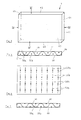
- Fig. 3 shows an inventive absorption element in an overview.
- the element 1 is of cuboid construction, the main surfaces being provided by two main cover plates 60, 61.
- the two longitudinal surfaces are formed by the side deck plates 62, 63, while the two end faces are provided by the side deck plates 64, 65.
- the side surfaces serve as a standing surface, so that the absorption element shown in Fig. 3 is also stackable.
- FIG. 4 shows the absorption element 1 shown in FIG. 3 in a sectional view along the lines IV-IV.
- the wave-shaped reflection plate 40 extends between the main cover plates 60, 61 over the entire surface thereof. In each case spaced from a wave trough dipole antennas 50a, 50b are arranged on both sides of the reflective plate 40.
- Reference symbol S denotes a region of the sectional view, which is shown in detail in FIG. 5.
- the wave structure in the described embodiment is composed of cylinder jacket segments, the radius of the cylinder segments being equal to R.
- the distance of the antennas, here the antenna 50b, to the wave trough is A.
- the distance of all dipole antennas to the respective associated trough is the same in the described embodiment.
- the distance A can be, for example, equal to half the radius of curvature, ie R / 2.
- M indicates in the drawing the center point for the curvature with the radius R.
- the distance A is set to (n + 1) ⁇ ⁇ ⁇ / 2, where n is a natural number is.
- Fig. 6 shows the absorption element according to the invention shown in Fig. 1 in a sectional view along the lines VI-VI, which runs parallel to one of the main cover plates 60 and 61, respectively.
- the front dipole antennas 50a and the rear dipole antennas 50b are offset from each other relative to a plane parallel to the main top plates 60, 61, so that only the rear dipole antennas 50b are in the illustrated plane in FIG.
- all the antennas 50a, 50b are electrically independent of each other, they each comprise only as described the two coordinated monopolies, which are connected to one another at the base via the resistor 53, see FIG.
- FIG. 7 corresponds to the sectional illustration of an absorption element shown in FIG. 4, but here the front-side antennas 50b and rear-side antennas 50a are placed at a different distance from the associated wave trough, such that they are arranged on the respective rear side of the two main cover plates 60, 61 issue.
- the distance between the respective dipole antenna and the associated trough is 2R in the example shown in FIG. 7, where R corresponds to the radius of curvature of such a wave trough.
- the arrangement of the antennas is relatively easy to accomplish, for example, the described antenna circuit arrangements can be printed on the back of the plates 60, 61.
- the two monopoles can be applied, in particular via a screen-printing process, and subsequently the resistor adapted to the impedance can be glued in with a conductive adhesive.
- the embodiments described so far are adapted to the absorption of electromagnetic high-frequency radiation of a predetermined polarization. Since in the reflection of electromagnetic radiation on metallic surfaces a Polarization rotation occurs by 90 °, it may be very advantageous if the absorption element according to the invention for absorbing electromagnetic high frequency radiation of different polarization is formed.
- Figures 8a and 8b show sections corresponding to those shown in Figures 4 and 6 by such, polarization independently working absorption element. Sections with perpendicular dipole antennas alternate with sections where the dipoles are oriented horizontally, see Figure 8b.
- an absorption element designed in this way captures and absorbs radiation with horizontal as well as radiation with vertical polarization.
- the wave structure of the reflection plate is adapted to the course of the dipole antennas. This means that in the sections in which the dipoles extend vertically, the wave structure is formed, for example, as indicated in FIG. 4. However, in those sections where the dipoles are horizontal, the wave structure is rotated 90 ° to the wave structure of the previous section, i. Wave troughs and wave crests also run there on horizontal straight lines, see FIG. 8a.
- antenna circuit arrangements which comprise an antenna dipole, wherein the reflection means is adapted to the geometry of the dipole antennas by means of the described wave structure.
- other antenna structures may be used, to which then the curvature of the reflection means is adapted.
- the absorption element according to the invention can be used in principle for all applications in which electromagnetic interference is to be destroyed.
Landscapes
- Aerials With Secondary Devices (AREA)
- Variable-Direction Aerials And Aerial Arrays (AREA)
- Inorganic Insulating Materials (AREA)
- Control Of Motors That Do Not Use Commutators (AREA)
- Shielding Devices Or Components To Electric Or Magnetic Fields (AREA)
Abstract
Description
- Die Erfindung betrifft ein Absorptionselement für elektromagnetische Hochfrequenzstrahlung, insbesondere für Strahlung, wie sie auf dem RFID (Radio Frequency Identification)-Gebiet zum Einsatz kommt.
- RFID ist eine Technologie zur berührungslosen automatischen Identifizierung von Objekten über Funk-Erkennung. Dabei werden auf sogenannten Transpondern abgelegte Daten berührungslos und ohne Sichtkontakt gelesen. Solche Transponder können an Objekten angebracht werden, welche dann anhand der darauf gespeicherten Daten automatisch und schnell identifizierbar sind. Ein RFID-Lesesystem regt dabei durch die Aussendung von elektromagnetischen Strahlung den Transponder zur Übertragung der auf dem Transponder gespeicherten Daten an. Diese Technologie kann überall dort eingesetzt werden, wo automatisch Objekte gekennzeichnet, erkannt, registriert, gelagert, überwacht oder transportiert werden müssen.
- Die Stärke der Felder bzw. die Frequenzen sind durch nationale und internationale Vorschriften festgelegt. Beispielsweise sind für den UHF-Bereich je nach Land und Zulassung drei bis ca. zehn verschiedene Frequenzen für die Übertragung zwischen Transponder und RFID-Lesesystem erlaubt. In bestimmten Anwendungen ist es notwendig, dass auf vergleichsweise kleinem Raum mehrere solcher RFID-Registrierungen durchgeführt werden. Dabei tritt zwischen den einzelnen Anwendungen solange keine Störung auf, wie unterschiedliche Frequenzen verwendet werden können. Durch die beschränkte Anzahl der zur Verfügung stehenden Frequenzen kann es jedoch sein, dass für unterschiedliche Anwendungen die gleiche Frequenz für die Übertragung zwischen Transponder und RFID-Lesesystem verwendet werden muss, obwohl sich die bei den Anwendungen erzeugten Strahlungsfelder räumlich überlappen. Dies wiederum kann die erwähnten Störungen zur Folge haben, was letztlich zumindest die Zuverlässigkeit der Registrierung erniedrigt bzw. auch die gleichzeitige Durchführbarkeit aller Anwendungen gefährden kann.
- Eine mögliche Lösung dieses Problems kann darin bestehen, dass die Leistung des RFID-Lesesystems an die jeweilig notwendige Reichweite angepasst wird. Dies erfordert jedoch einen Eingriff in die elektrische Schaltung des RFID-Lesesystems bzw. erfordert einen erhöhten Schaltungsaufwand.
- Insofern liegt der Erfindung die Aufgabe zugrunde, das beschriebene Problem bei der Nutzung einer RFID-Registrierung zumindest teilweise zu beheben.
- Diese Aufgabe löst die Erfindung auf überraschend einfache Weise schon mit einem Absorptionselement für elektromagnetische Hochfrequenzstrahlung mit den Merkmalen von Anspruch 1.
- Dabei weist das Absorptionselement eine Reflexionseinrichtung mit gekrümmter Reflexionsfläche mit einer Mehrzahl von die Hochfrequenzstrahlung fokussierenden Abschnitten zur Erzeugung einer Mehrzahl von Bereichen mit erhöhter Feldstärke vor der Reflexionseinrichtung sowie einer Mehrzahl von an die Frequenz der Strahlung angepassten Antennenschaltungsanordnungen, die jeweils eine Antennenleiterstruktur zur Aufnahme von Strahlungsenergie und ein Mittel zur Umwandlung der aufgenommenen Strahlungsenergie in eine andere Energieform aufweisen. Mit solchen erfindungsgemäß ausgebildeten Absorptionselementen kann die Ausbreitung in solche Raumgebiete vermieden werden, in welchen Strahlung gleicher Frequenz für eine RFID-Registrierung verwendet wird, sodass letztlich eine gegenseitige Störung der unterschiedlichen RFID-Anwendungen verhindert wird. Darüber hinaus kann bei einer einzelnen RFID-Anwendung mittels eines solchen erfindungsgemäßen Absorptionselements verhindert werden, dass elektromagnetische Strahlung sich in Raumbereiche ausbreitet, in welche dies unerwünscht ist.
- Der Erfindung liegt die Idee zugrunde, die Ausbreitung von elektromagnetischer Hochfrequenzstrahlung in bestimmte Raumgebiete dadurch zu verhindern, dass eine Vorrichtung vorgesehen ist, welche einerseits die Strahlung reflektiert, jedoch darüber hinaus auch dafür sorgt, dass die Strahlung absorbiert, d.h. in eine andere Energieform umgewandelt wird, sodass auch keine Störungen durch mehrfach reflektierte Hochfrequenzstrahlung auftreten kann. Dabei werden Hochfrequenzstrahlung und thermische Strahlung als unterschiedliche Energieformen betrachtet.
- Dabei kann es zweckmäßig sein, wenn eine Antennenschaltungsanordnung vor der Reflexionseinrichtung gerade in einem Bereich erhöhter Feldstärke angeordnet ist, sodass die Strahlung mit einem hohen Wirkungsgrad von der Antennenschaltungsanordnung aufgenommen wird.
- Vorzugsweise ist das Mittel zur Umwandlung der aufgenommenen Strahlungsenergie zur Erzeugung von thermischer Energie ausgebildet und kann beispielsweise einen Widerstand umfassen, der an die Antennenleiterstruktur angeschlossen ist.
- In einer anderen Ausführungsform kann das Mittel zur Umwandlung der aufgenommenen Strahlungsenergie einen Elektrolumineszenzstrahler wie beispielsweise eine Leuchtdiode umfassen, welche an die Antennenleiterstruktur angeschlossen ist.
- Sowohl bei der Erzeugung von thermischer Energie als auch bei der Erzeugung von sichtbaren Photonen durch das Mittel zur Umwandlung der aufgenommenen Strahlungsenergie wird die von der Antenne aufgenommene Strahlungsenergie in elektrische Energie umgewandelt, welche wiederum entweder in IR-Strahlung oder in sichtbare Strahlung umgewandelt wird. Bei der Erzeugung von Licht durch das Absorptionselement kann dem Benutzer visuell die Wirksamkeit des erfindungsgemäßen Absorptionselements angezeigt werden.
- Um die elektromagnetische Strahlung besonders wirkungsvoll aufzunehmen, kann vorgesehen sein, dass eine Antennenschaltungsanordnung in einem Bereich erhöhter Feldstärke vor dem Reflexionseinrichtung so angeordnet ist, dass die Antennenleiterstruktur zur fokussierten Strahlung ausgerichtet ist. Zweckmäßigerweise kann dabei die Antennenstruktur an den Feldstärkeverlauf in den Bereichen mit erhöhter Feldstärke angepasst sein.
- Zweckmäßigerweise kann die Reflexionsfläche, d.h. die Oberfläche der Reflexionseinrichtung eine Wellenstruktur, insbesondere eine ebene Wellenstruktur aufweisen. Dabei weist die Reflexionsfläche Berge und Täler auf, die auf Geraden verlaufen. Eine solche Wellenstruktur kann als eine Art Nebeneinanderanordnung einer Mehrzahl von Zylinderlinsen für elektromagnetische Strahlung ausgebildet sein.
- Um ein Absorptionselement bereitzustellen, welches polarisationsunabhängig arbeitet, kann vorgesehen sein, dass die Reflexionsfläche der Reflexionseinrichtung zueinander benachbarte unterschiedliche Wellenstrukturbereiche umfasst, wobei die Wellentäler bzw. Wellenberge benachbarter Wellenstrukturbereiche senkrecht zueinander angeordnet sind.
- Zur Aufnahme der elektrischen Felder vor der Reflexionsfläche, insbesondere in den Bereichen mit erhöhter Feldstärke kann vorgesehen sein, die Antennenleiterstruktur der Antennenschaltungsanordnungen in Form einer Dipolstruktur auszubilden. Eine solche Dipolleiterstruktur ist besonders gut an die von den beschriebenen Wellenstrukturbereichen der Reflexionsfläche erzeugten Felder geeignet. Dabei kann es zweckmäßig sein, wenn die Achse der Dipolstruktur parallel zu einem Wellenberg bzw. einem Wellental der Wellenstruktur an der Reflexionsfläche der Reflexionseinrichtung platziert ist, d.h. dass die Dipolleiterstruktur zur Wellenstruktur der Reflexionsfläche ausgerichtet ist.
- Die Einkopplung der Strahlung in die Antennenleiterstruktur kann erhöht werden, wenn der Abstand der Antennenleiterstruktur zur Reflexionsfläche ein vorgegebener Abstand ist. Dabei kann es zweckmäßig sein, wenn dieser Abstand gleich einem ungeradzahligen Vielfachen der halben Wellenlänge der Hochfrequenzstrahlung ist. Damit ist sichergestellt, dass sich die von der Reflexionsfläche der Reflexionseinrichtung reflektierte Strahlung konstruktiv mit der einfallenden Strahlung am Ort der Antennenleiterstruktur überlagert.
- Besonders zweckmäßig ist es, wenn zu beiden Seiten der Reflexionseinrichtung Antennenschaltungsanordnungen vorgesehen sind, sodass von beiden Seiten einfallende Strahlung von dem erfindungsgemäßen Absorptionselement eliminiert werden kann.
- Es kann zweckmäßig sein, wenn die Reflexionseinrichtung ein Blech oder ein Drahtgeflecht umfasst. Mit einem solchen Blech oder Geflecht lassen sich auf einfache Weise mittels bekannter Umformungstechniken vorteilhafte Oberflächenstrukturen, insbesondere die oben stehend erwähnten Wellenstrukturbereiche erzeugen. Zum Schutz der Oberflächenstruktur der Reflexionseinrichtung kann vorgesehen sein, dass zumindest die beiden Hauptflächen der Reflexionseinrichtung jeweils durch eine plattenförmige Einrichtung abgedeckt sind. Notwendige Bedingung ist dabei, dass das plattenförmige Element oder die plattenförmige Einrichtung ein Material umfasst, welches die zu absorbierende Strahlung durchlässt und insbesondere keinen hohen Reflexionsgrad für die elektromagnetische Strahlung aufweist.
- In solchen Fällen, bei welchen die Reflexionseinrichtung eine Wellenstruktur aufweist, kann die Abdeckeinrichtung insbesondere direkt auf der Reflexionseinrichtung aufliegen, sodass sich die Wellentäler bzw. -berge an den beiden Abdeckeinrichtungen abstützen.
- Bei der Verwendung solcher Abdeckeinrichtungen kann es zweckmäßig sein, wenn die Antennenschaltungsanordnungen an der Oberfläche der Abdeckeinrichtung angeordnet sind, wodurch diese auf besonders einfache Weise ortsgenau, beispielsweise über ein Druckverfahren wie ein Siebdruckverfahren angeordnet werden können.
- Das erfindungsgemäße Absorptionselement kann prinzipiell mit beliebigen Abmessungen hergestellt werden. Dabei kann es vorteilhaft sein, wenn das Element stapelbar ist, sodass ausgehend von der Größe des Absorptionselements beliebig große Absorptionsflächen oder -wände erzeugbar sind. Dabei ist es zweckmäßig, wenn das erfindungsgemäße Absorptionselement in seinen Abmessungen bzw. seinem Gewicht manuell transportabel gestaltet ist.
- Die Erfindung wird im Folgenden durch das Beschreiben einiger Ausführungsformen des erfindungsgemäßen Absorptionselements unter Bezugnahme auf die beiliegenden Zeichnungen erläutert, wobei
- Fig. 1
- eine Anwendungssituation für ein erfindungsgemäßes Absorptionselement,
- Fig. 2a
- eine Reflexionseinrichtung im Ausschnitt zur Verwendung in einem erfindungsgemäßen Absorptionselement,
- Fig. 2b
- eine Antennenschaltungsanordnung zur Verwendung in einem erfindungsgemäßen Absorptionselement,
- Fig. 3
- ein erfindungsgemäß ausgebildetes Absorptionselement in einer Aufsicht,
- Fig. 4
- das in Fig. 3 gezeigte Absorptionselement in einer Schnittdarstellung entlang der Linien IV,
- Fig. 5
- den mit dem Bezugszeichen S gekennzeichneten Ausschnitt von Fig. 4 in einer Detailansicht,
- Fig. 6
- das in Fig. 3 dargestellt Absorptionselement in einer Schnittdarstellung entlang den Linien VI,
- Fig. 7
- eine Schnittdarstellung ähnlich der in Fig. 4 gezeigten für eine weitere Ausführungsform eines erfindungsgemäßen Absorptionselements,
- Fig. 8a
- eine Schnittdarstellung entsprechend der in Fig. 4 gezeigten Schnittansicht für eine weitere Ausführungsform eines erfindungsgemäßen Absorptionselements, und
- Fig. 8b
- eine Schnittdarstellung entsprechend der in Fig. 6 gezeigten Schnittansicht für die in Fig. 8a gezeigte weitere Ausführungsform eines erfindungsgemäßen Absorptionselements
- In Fig. 1 ist eine Anwendungssituation für ein erfindungsgemäßes Absorptionselement 1, 2, 3, 4 dargestellt. Die Figur zeigt eine äußere Hallenwand 30, bei welcher beabstandet zueinander zwei Rollentore 31a, 31b angeordnet sind. Diese Tore können beispielsweise von einem Lkw angefahren werden, derartig, dass die Ladefläche zu dem Tor ausgerichtet ist. Mit einem Transportmittel wie beispielsweise einem Gabelstapler, welcher sich durch das jeweilige Tor in die Ladefläche des Lkws bewegt, können Gegenstände aufgenommen und durch das besagte Tor in die Halle eingebracht werden. In der beschriebenen Situation sind diese Gegenstände jeweils mit einem Transponder versehen, welcher von einem RFID-Lesesystem, das im Bereich des Tors platziert ist, erfasst werden.
- In der Figur ist beispielhaft in jedem der Tore 31a, 31b ein Transponder 22a, 22b gezeigt, welcher jeweils eine Transponderantenne 23a, b umfasst. Sobald der jeweilige Transponder in den Wirkbereich der RFID-Leseeinrichtung 20a, 20b, welche jeweils eine RFID-Antenne 21a, 21b aufweist, eintritt, wird der jeweilige Transponder erfasst und vom System registriert. Werden beide Tore gleichzeitig zur Einbringung in die Halle von jeweils mit einem Transponder gekennzeichneten Waren verwendet, können sich die elektromagnetischen Felder, welche durch den Datenaustausch zwischen dem RFID-Lesesystem 20a und dem zugehörigen Transponder 22a bzw. den RFID-Lesesystem 20b und dem zugeordneten Transponder 22b erzeugt werden, stören. Eine solche Störung tritt insbesondere dann auf, wenn die RFID-Erkennungssysteme mit den gleichen Frequenzen arbeiten.
- Zur Behebung dieser Störungen kann eines oder mehrere der erfindungsgemäßen Absorptionselemente verwendet werden. In der Figur sind vier Elemente 1 - 4 im Innern der Halle dargestellt, von welchen jeweils zwei übereinander gestapelt sind, derartig, dass sie sich etwa senkrecht zur Hallenwand 30 in den Halleninnenraum hinein erstrecken. Wird beispielsweise von der Antenne 21a des RFID-Lesesystems 20a elektromagnetische Hochfrequenzstrahlung in Richtung zum benachbarten RFID-Lesesystem 20b bzw. deren Antenne 21b abgestrahlt, wird diese Strahlung durch die wie dargestellt angeordneten Absorptionselemente 1,2 reflektiert und absorbiert, sodass diese Strahlung nicht zu Fehlerfassungen führen kann. Besonders zweckmäßig kann es dabei wie in der Figur 1 dargestellt sein, auch an dem zweiten Tor 31b solche Absorptionselemente 3, 4 aufzustellen, sodass alle Torerfassungen in Bezug auf die torspezifischen elektromagnetischen Strahlungen entkoppelt sind.
- Ein erfindungsgemäßes Absorptionselement für elektromagnetische Hochfrequenzstrahlung in der beschriebenen Ausführungsform umfasst elementare Bauteile, die in den Figuren 2a, b dargestellt sind. Fig. 2a zeigt ein dünnes Metallblech 40, welches eine ebene Wellenstruktur mit Wellenbergen 42 und Wellentälern 41 umfasst, wobei die Wellentäler bzw. Wellenberge jeweils auf einer Geraden verlaufen. Das Blech wird für auftreffende elektromagnetische Hochfrequenzstrahlung durch die gekrümmten Abschnitte fokussieren, sodass vor dem Blech nach der Reflexion der Strahlung Bereiche mit erhöhter Feldstärke entstehen.
- An diesen Stellen erhöhter Feldstärke sind erfindungsgemäß in noch zu beschreibender Weise Dipolantennen angeordnet, siehe Fig. 2b, welche eine solche Dipolantenne 50 zeigt. Sie umfasst zwei Monopole 51, 52 als Antennenleiterstrukturen, wobei am Fußpunkt ein an die Impedanz des Dipols angepasster Verlustwiderstand 53 angeordnet ist, welcher beide Monopole 51, 52 elektrisch miteinander verbindet. Der Dipol weist eine elektrische Länge L auf, die einem ungeradzahligen Vielfachen von λ/2 entspricht, wobei λ die Wellenlänge der elektromagnetischen Hochfrequenzstrahlung ist. In dem angegebenen Beispiel umfasst das Strahlungsfeld UHF mit einer Wellenlänge von 30 cm. Die ebene Wellenstruktur des Reflexionsblechs 40 weist die Eigenschaft von nebeneinander angeordneten Zylinderlinsen auf, insofern ist die in Fig. 2b angegebene Dipolantenne an die von dem Reflexionsblech 40 erzeugten Bereiche erhöhter Feldstärke angepasst. Die in Fig. 2b angegebene Antenne nimmt das elektromagnetische Hochfrequenzfeld auf, wobei die aufgenommene Energie mittels des Impedanz angepassten Widerstands 53 in thermische Energie umgewandelt wird.
- Fig. 3 zeigt ein erfindungsgemäßes Absorptionselement in einer Übersichtsdarstellung. Das Element 1 ist quaderförmig aufgebaut, wobei die Hauptflächen durch zwei Hauptdeckplatten 60, 61 bereitgestellt werden. Die beiden Längsflächen werden durch die Seitendeckplatten 62, 63 gebildet, während die beiden Stirnflächen durch die Seitendeckplatten 64, 65 bereitgestellt werden. Die Seitenflächen dienen als Standfläche, sodass das in Fig. 3 dargestellte Absorptionselement auch stapelbar ist.
- Fig. 4 zeigt das in Fig. 3 dargestellte Absorptionselement 1 in einer Schnittdarstellung entlang der Linien IV-IV. Das wellenförmige Reflexionsblech 40 erstreckt sich zwischen den Hauptdeckplatten 60, 61 über deren gesamte Fläche. Jeweils beabstandet von einem Wellental sind Dipolantennen 50a, 50b zu beiden Seiten des Reflexionsblechs 40 angeordnet.
- Das Bezugszeichen S bezeichnet einen Bereich der Schnittdarstellung, welcher in Fig. 5 im Detail gezeigt ist. Wie zu erkennen, setzt sich die Wellenstruktur in der beschriebenen Ausführungsform aus Zylindermantelsegmenten zusammen, wobei der Radius der Zylindersegmente gleich R ist. Der Abstand der Antennen, hier der Antenne 50b, zum Wellental beträgt A. Wie aus Figur 4 ersichtlich, ist der Abstand aller Dipolantennen zum jeweils zugeordneten Wellental in der beschriebenen Ausführungsform gleich. Je nach Ausführungsform der Erfindung kann der Abstand A beispielsweise gleich dem halben Krümmungsradius, d.h. R/2 betragen. M gibt in der Zeichnung den Mittelpunkt für die Krümmung mit dem Radius R an. Um zu vermeiden, dass einfallende elektromagnetische Hochfrequenzstrahlung mit der durch das Reflexionsblech 40 reflektierten Strahlung am Ort der Dipolantenne destruktiv interferiert, kann vorgesehen sein, dass der Abstand A eingestellt ist auf (n + 1) •̇ λ/2, wobei n eine natürliche Zahl ist.
- Fig. 6 zeigt das in Fig. 1 dargestellte erfindungsgemäße Absorptionselement in einer Schnittdarstellung entlang der Linien VI-VI, welche parallel zu einer der Hauptdeckplatten 60 bzw. 61 verläuft. Wie in Fig. 4 angegeben, sind die vorderen Dipolantennen 50a und die hinteren Dipolantennen 50b relativ zu einer Ebene parallel zu den Hauptdeckplatten 60, 61 zueinander versetzt, sodass in Fig. 6 nur die hinteren Dipolantennen 50b in der dargestellten Ebene liegen. Wie in dem angegebenen Beispiel dargestellt, sind alle Antennen 50a, 50b elektrisch unabhängig voneinander, sie umfassen jeweils nur wie beschrieben die beiden aufeinander abgestimmten Monopole, welche am Fußpunkt über den Widerstand 53 miteinander verbunden sind, siehe Fig. 2.
- Fig. 7 entspricht der in Fig. 4 gezeigten Schnittdarstellung eines Absorptionselements, hier sind jedoch die vorderseitigen Antennen 50b bzw. rückseitigen Antennen 50a in einem anderen Abstand zu dem zugeordneten Wellental platziert, derartig, dass sie an der jeweiligen Rückseite der beiden Hauptdeckplatten 60, 61 anliegen. Der Abstand der jeweiligen Dipolantenne zu dem zugeordneten Wellental beträgt in dem in Fig. 7 dargestellten Beispiel insofern 2R, wobei R der Krümmungsradius eines solchen Wellentales entspricht. Bei einer derartigen Ausführungsform der Erfindung ist die Anordnung der Antennen vergleichsweise einfach zu bewerkstelligen, beispielsweise können die beschriebenen Antennenschaltungsanordnungen auf die Rückseite der Platten 60, 61 aufgedruckt werden. Dabei können insbesondere über ein Siebdruckverfahren die beiden Monopole aufgebracht werden und nachfolgend der Impedanz angepasste Widerstand mit einem leitfähigen Kleber eingeklebt werden.
- Die bislang beschriebenen Ausführungsformen sind auf die Absorption von elektromagnetischer Hochfrequenzstrahlung einer vorgegebenen Polarisation ausgebildet. Da bei der Reflexion von elektromagnetischer Strahlung an metallischen Oberflächen eine Polarisationsdrehung um 90° auftritt, kann es sehr vorteilhaft sein, wenn das erfindungsgemäße Absorptionselement zum Absorbieren von elektromagnetischer Hochfrequenzstrahlung unterschiedlicher Polarisation ausgebildet ist.
- die Figuren 8a und 8b zeigen Schnitte entsprechend den in den Figuren 4 und 6 gezeigten durch ein solches, polarisationsunabhängig arbeitendes Absorptionselement. Abschnitte mit senkrecht verlaufenden Dipolantennen wechseln sich ab mit Abschnitten, bei welchen die Dipole horizontal ausgerichtet sind, siehe Figur 8b. Insofern erfasst und absorbiert ein derartig gestaltetes Absorptionselement sowohl Strahlung mit horizontaler als auch Strahlung mit vertikaler Polarisation. Es versteht sich, dass die Wellenstruktur des Reflexionsblechs an den Verlauf der Dipolantennen angepasst ist. Dies bedeutet, dass in den Abschnitten, bei welchen die Dipole vertikal verlaufen, die Wellenstruktur beispielsweise wie in Fig. 4 angegeben, ausgebildet ist. In solchen Abschnitten, bei welchen die Dipole horizontal verlaufen, ist die Wellenstruktur jedoch zu der Wellenstruktur des vorhergehenden Abschnittes um 90° gedreht, d.h. Wellentäler und Wellenberge verlaufen dort auch auf horizontalen Geraden, siehe Figur 8a.
- Es sei darauf hingewiesen, dass die Erfindung unter Nutzung von Antennenschaltungsanordnungen beschrieben wurden, die einen Antennendipol umfassen, wobei die Reflexionseinrichtung mittels der beschriebenen Wellenstruktur an die Geometrie der Dipolantennen angepasst ist. In nicht dargestellten Ausführungsformen können auch andere Antennenstrukturen verwendet werden, an die dann die Krümmung der Reflexionseinrichtung angepasst ist.
- Das erfindungsgemäße Absorptionselement kann prinzipiell für alle Anwendungen benutzt werden, bei welchen elektromagnetische Störstrahlung vernichtet werden soll.
-
- 1
- Absorptionselement
- 2
- Absorptionselement
- 3
- Absorptionselement
- 4
- Absorptionselement
- 10, 11
- Rolltor
- 20a, b
- RFID-Lesesystem
- 21a, b
- RFID-Antenne
- 22a, b
- Transponder
- 23a, b
- Transponderantenne
- 30
- Hallenwand
- 31a, b
- Hallentor
- 40
- Reflexionsblech
- 41
- Wellental
- 42
- Wellenberg
- 50, 50a,b
- Dipolantenne
- 51, 52
- gerader Leiter
- 53
- Widerstand
- 60, 61
- Hauptdeckplatte
- 62, 63
- Seitendeckplatte
- 64, 65
- Seitendeckplatte
- S
- Ausschnitt
- L
- Dipollänge
- M
- Mittelpunkt
Claims (14)
- Absorptionselement (1) für elektromagnetische Hochfrequenzstrahlung, umfassend eine Reflexionseinrichtung (40) mit gekrümmter Reflexionsfläche mit einer Mehrzahl von die Hochfrequenzstrahlung fokussierenden Abschnitten zur Erzeugung einer Mehrzahl von Bereichen mit erhöhter Feldstärke vor der Reflexionseinrichtung sowie einer Mehrzahl von an die Frequenz der Strahlung angepassten Antennenschaltungsanordnungen (50a, 50b), die jeweils eine Antennenleiterstruktur (51, 52) zur Aufnahme von Strahlungsenergie und ein Mittel (53) zur Umwandlung der aufgenommenen Strahlungsenergie in eine andere Energieform aufweist.
- Absorptionselement nach Anspruch 1, dadurch gekennzeichnet , dass das Mittel zur Umwandlung der aufgenommenen Strahlungsenergie thermische Energie erzeugt und insbesondere einen Widerstand (53) umfasst, welcher an die Antennenleiterstruktur (51, 52) angeschlossen ist.
- Absorptionselement nach Anspruch 1, dadurch gek e n n z e i c h n e t , d a s s das Mittel zur Umwandlung der aufgenommenen Strahlungsenergie einen Elektrolizmineszenzstrahler wie eine Leuchtdiode umfasst, welcher an die Antennenleiterstruktur angeschlossen ist.
- Absorptionselement nach Anspruch 1, 2 oder 3, dadurch gekennzeichnet , dass eine Antennenschaltungsanordnung (50a, 50b) in einem Bereich erhöhter Feldstärke vor der Reflexionseinrichtung (40) so angeordnet sind, dass die Antennenleiterstruktur zur fokussierten Strahlung ausgerichtet ist.
- Absorptionselement nach einem der Ansprüche 1 bis 4, dadurch gekennzeichnet , dass die Reflexionsfläche der Reflexionseinrichtung (40) eine Wellenstruktur, insbesondere eine ebene Wellenstruktur aufweist.
- Absorptionselement Anspruch 5, dadurch gekennzeichnet , dass die Reflexionsfläche zueinander benachbarte Wellenstrukturbereiche umfasst, wobei die Wellentäler (41) bzw. Wellenberge (42) benachbarter Wellenstrukturbereiche senkrecht zueinander angeordnet sind.
- Absorptionselement einem der Ansprüche 1 bis 6, dadurch gekennzeichnet , dass die Antennenleiterstruktur (51, 52) eine Dipolleiterstruktur aufweist.
- Absorptionselement einem der Ansprüche 1 bis 7, dadurch gekennzeichnet , dass die Antennenleiterstruktur in einem vorgegebenen Abstand zur Reflexionseinrichtung angeordnet ist, insbesondere in einem Abstand zur Reflexionsfläche gleich einem ungeradzahligen Vielfachen der halben Wellenlänge der Hochfrequenzstrahlung.
- Absorptionselement einem der Ansprüche 1 bis 8, dadurch gekennzeichnet , dass zu beiden Seiten der Reflexionseinrichtung (40) Antennenschaltungsanordnungen (51, 52) vorgesehen sind.
- Absorptionselement einem der Ansprüche 1 bis 9, dadurch gekennzeichnet, dass die Reflexionseinrichtung ein Blech oder ein Drahtgeflecht umfasst.
- Absorptionselement einem der Ansprüche 1 bis 10, dadurch gekennzeichnet , dass zumindest eine der beiden Hauptflächen der Reflexionseinrichtung durch eine plattenförmiges Abdeckeinrichtung (60, 61) abgedeckt sind.
- Absorptionselement nach Anspruch 11, dadurch gekennzeichnet , dass Antennenschaltungsanordnungen (50a, 50b) an einem plattenförmigen Element (60, 61) angebracht sind.
- Absorptionselement nach Anspruch 12, dadurch gekennzeichnet , dass Antennenleiterstrukturen der Antennenschaltungsanordnungen mittels eines Druckverfahrens wie einem Siebdruckverfahren auf ein plattenförmiges Element aufgebracht sind.
- Absorptionselement einem der Ansprüche 1 bis 13, dadurch gekennzeichnet , dass das Absorptionselement auf einer seiner Seitenflächen (62, 63, 64, 65) aufstellbar und stapelbar ausgebildet ist.
Applications Claiming Priority (1)
| Application Number | Priority Date | Filing Date | Title |
|---|---|---|---|
| DE202006008437U DE202006008437U1 (de) | 2006-05-24 | 2006-05-24 | Absorptionselement für elektromagnetische Hochfrequenzstrahlung |
Publications (2)
| Publication Number | Publication Date |
|---|---|
| EP1860733A1 true EP1860733A1 (de) | 2007-11-28 |
| EP1860733B1 EP1860733B1 (de) | 2010-04-14 |
Family
ID=38290028
Family Applications (1)
| Application Number | Title | Priority Date | Filing Date |
|---|---|---|---|
| EP07010006A Not-in-force EP1860733B1 (de) | 2006-05-24 | 2007-05-19 | Absorptionselement für elektromagnetische Hochfrequenzstrahlung |
Country Status (3)
| Country | Link |
|---|---|
| EP (1) | EP1860733B1 (de) |
| AT (1) | ATE464675T1 (de) |
| DE (2) | DE202006008437U1 (de) |
Cited By (2)
| Publication number | Priority date | Publication date | Assignee | Title |
|---|---|---|---|---|
| EP3089269A1 (de) * | 2015-04-30 | 2016-11-02 | Airbus Operations (S.A.S.) | Absorptionsvorrichtung für elektromagnetische wellen zur befestigung an einer wand |
| CN115460902A (zh) * | 2022-09-30 | 2022-12-09 | 紫光计算机科技有限公司 | 电磁辐射的消除方法及消除装置、电子设备 |
Citations (3)
| Publication number | Priority date | Publication date | Assignee | Title |
|---|---|---|---|---|
| US4482897A (en) | 1982-06-28 | 1984-11-13 | At&T Bell Laboratories | Multibeam segmented reflector antennas |
| GB2251338A (en) * | 1985-10-15 | 1992-07-01 | Secr Defence | Microwave absorber |
| WO1994024724A1 (en) | 1993-04-09 | 1994-10-27 | Chomerics, Inc. | Broadband electromagnetic energy absorber |
Family Cites Families (2)
| Publication number | Priority date | Publication date | Assignee | Title |
|---|---|---|---|---|
| US3599210A (en) * | 1969-11-18 | 1971-08-10 | Us Navy | Radar absorptive coating |
| US5325094A (en) * | 1986-11-25 | 1994-06-28 | Chomerics, Inc. | Electromagnetic energy absorbing structure |
-
2006
- 2006-05-24 DE DE202006008437U patent/DE202006008437U1/de not_active Expired - Lifetime
-
2007
- 2007-05-19 AT AT07010006T patent/ATE464675T1/de active
- 2007-05-19 EP EP07010006A patent/EP1860733B1/de not_active Not-in-force
- 2007-05-19 DE DE502007003440T patent/DE502007003440D1/de active Active
Patent Citations (3)
| Publication number | Priority date | Publication date | Assignee | Title |
|---|---|---|---|---|
| US4482897A (en) | 1982-06-28 | 1984-11-13 | At&T Bell Laboratories | Multibeam segmented reflector antennas |
| GB2251338A (en) * | 1985-10-15 | 1992-07-01 | Secr Defence | Microwave absorber |
| WO1994024724A1 (en) | 1993-04-09 | 1994-10-27 | Chomerics, Inc. | Broadband electromagnetic energy absorber |
Cited By (4)
| Publication number | Priority date | Publication date | Assignee | Title |
|---|---|---|---|---|
| EP3089269A1 (de) * | 2015-04-30 | 2016-11-02 | Airbus Operations (S.A.S.) | Absorptionsvorrichtung für elektromagnetische wellen zur befestigung an einer wand |
| FR3035742A1 (fr) * | 2015-04-30 | 2016-11-04 | Airbus Operations Sas | Dispositif d'absorption d'ondes electromagnetiques destine a etre fixe sur une paroi |
| US9991603B2 (en) | 2015-04-30 | 2018-06-05 | Airbus Operations (Sas) | Device, intended to be fixed on a wall, for absorbing electromagnetic waves |
| CN115460902A (zh) * | 2022-09-30 | 2022-12-09 | 紫光计算机科技有限公司 | 电磁辐射的消除方法及消除装置、电子设备 |
Also Published As
| Publication number | Publication date |
|---|---|
| ATE464675T1 (de) | 2010-04-15 |
| EP1860733B1 (de) | 2010-04-14 |
| DE202006008437U1 (de) | 2007-09-27 |
| DE502007003440D1 (de) | 2010-05-27 |
Similar Documents
| Publication | Publication Date | Title |
|---|---|---|
| EP2176681B1 (de) | Radarsensor für kraftfahrzeuge | |
| DE602004006348T2 (de) | HF-Etikettenmodul und Artikel mit einem HF-Etikettenmodul | |
| DE69613244T2 (de) | Planare gruppenantenne für zwei frequenzen | |
| DE102006050344B4 (de) | Aufnahmebehälter mit RFID-Etikett | |
| DE2815453A1 (de) | Streuungsfreie ultrahochfrequenzantenne mit elektronischer ablenkung | |
| EP3918172B1 (de) | Isolierverglasungseinheit und verglasung | |
| DE2362913B2 (de) | Spiralantenne | |
| DE202022107107U1 (de) | Integrierte Basisstationsantenne | |
| EP1678787A1 (de) | Vorrichtung sowie verfahren zum abstrahlen und/oder zum empfangen von elektromagnetischer strahlung | |
| DE2427505A1 (de) | Antennensystem mit einem in offener bauweise ausgebildeten reflektor | |
| DE3217437A1 (de) | Mikrowellen-richtantenne aus einer dielektrischen leitung | |
| DE948705C (de) | Antennenanordnung fuer den Dezimeterwellenbereich | |
| EP1860733B1 (de) | Absorptionselement für elektromagnetische Hochfrequenzstrahlung | |
| DE3027093C2 (de) | Umpolarisiereinrichtung zur Erzeugung zirkular polarisierter elektromagnetischer Wellen | |
| DE2335792A1 (de) | Funknavigations-, insbesondere landesystem | |
| DE112017000933B4 (de) | Radar mit reichweitenunabhängiger Auflösung | |
| DE3700886A1 (de) | Hohlleiterschlitzantenne fuer doppler-navigatoren | |
| DE2330654C3 (de) | Strahlerzeile, bei der das keulenförmige Strahlungsdiagramm durch Frequenzänderung schwenkbar ist | |
| WO2007131879A1 (de) | Testvorrichtung mit hf-/uhf-dualbandantenne zum testen von rfid-transpondern in einem fertigungsgerät | |
| DE518622C (de) | Mehrfachantenne | |
| DE102012101443A9 (de) | Planare Antennenanordnung | |
| DE102006062308A1 (de) | Passives Detektierplättchen | |
| DE1591040A1 (de) | Sendeantenne | |
| EP4010556A1 (de) | Verglasung mit rfid-transponder | |
| DE112017005061T5 (de) | Erweiterte Antennensysteme |
Legal Events
| Date | Code | Title | Description |
|---|---|---|---|
| PUAI | Public reference made under article 153(3) epc to a published international application that has entered the european phase |
Free format text: ORIGINAL CODE: 0009012 |
|
| AK | Designated contracting states |
Kind code of ref document: A1 Designated state(s): AT BE BG CH CY CZ DE DK EE ES FI FR GB GR HU IE IS IT LI LT LU LV MC MT NL PL PT RO SE SI SK TR |
|
| AX | Request for extension of the european patent |
Extension state: AL BA HR MK YU |
|
| 17P | Request for examination filed |
Effective date: 20080527 |
|
| RAP1 | Party data changed (applicant data changed or rights of an application transferred) |
Owner name: ZETES GMBH |
|
| 17Q | First examination report despatched |
Effective date: 20080701 |
|
| AKX | Designation fees paid |
Designated state(s): AT BE BG CH CY CZ DE DK EE ES FI FR GB GR HU IE IS IT LI LT LU LV MC MT NL PL PT RO SE SI SK TR |
|
| GRAP | Despatch of communication of intention to grant a patent |
Free format text: ORIGINAL CODE: EPIDOSNIGR1 |
|
| GRAS | Grant fee paid |
Free format text: ORIGINAL CODE: EPIDOSNIGR3 |
|
| GRAA | (expected) grant |
Free format text: ORIGINAL CODE: 0009210 |
|
| AK | Designated contracting states |
Kind code of ref document: B1 Designated state(s): AT BE BG CH CY CZ DE DK EE ES FI FR GB GR HU IE IS IT LI LT LU LV MC MT NL PL PT RO SE SI SK TR |
|
| REG | Reference to a national code |
Ref country code: GB Ref legal event code: FG4D Free format text: NOT ENGLISH |
|
| REG | Reference to a national code |
Ref country code: CH Ref legal event code: EP |
|
| REG | Reference to a national code |
Ref country code: IE Ref legal event code: FG4D Free format text: LANGUAGE OF EP DOCUMENT: GERMAN |
|
| REF | Corresponds to: |
Ref document number: 502007003440 Country of ref document: DE Date of ref document: 20100527 Kind code of ref document: P |
|
| REG | Reference to a national code |
Ref country code: NL Ref legal event code: VDEP Effective date: 20100414 |
|
| LTIE | Lt: invalidation of european patent or patent extension |
Effective date: 20100414 |
|
| PG25 | Lapsed in a contracting state [announced via postgrant information from national office to epo] |
Ref country code: SE Free format text: LAPSE BECAUSE OF FAILURE TO SUBMIT A TRANSLATION OF THE DESCRIPTION OR TO PAY THE FEE WITHIN THE PRESCRIBED TIME-LIMIT Effective date: 20100414 Ref country code: ES Free format text: LAPSE BECAUSE OF FAILURE TO SUBMIT A TRANSLATION OF THE DESCRIPTION OR TO PAY THE FEE WITHIN THE PRESCRIBED TIME-LIMIT Effective date: 20100725 Ref country code: NL Free format text: LAPSE BECAUSE OF FAILURE TO SUBMIT A TRANSLATION OF THE DESCRIPTION OR TO PAY THE FEE WITHIN THE PRESCRIBED TIME-LIMIT Effective date: 20100414 Ref country code: LT Free format text: LAPSE BECAUSE OF FAILURE TO SUBMIT A TRANSLATION OF THE DESCRIPTION OR TO PAY THE FEE WITHIN THE PRESCRIBED TIME-LIMIT Effective date: 20100414 |
|
| REG | Reference to a national code |
Ref country code: IE Ref legal event code: FD4D |
|
| BERE | Be: lapsed |
Owner name: ZETES G.M.B.H. Effective date: 20100531 |
|
| PG25 | Lapsed in a contracting state [announced via postgrant information from national office to epo] |
Ref country code: LV Free format text: LAPSE BECAUSE OF FAILURE TO SUBMIT A TRANSLATION OF THE DESCRIPTION OR TO PAY THE FEE WITHIN THE PRESCRIBED TIME-LIMIT Effective date: 20100414 Ref country code: SI Free format text: LAPSE BECAUSE OF FAILURE TO SUBMIT A TRANSLATION OF THE DESCRIPTION OR TO PAY THE FEE WITHIN THE PRESCRIBED TIME-LIMIT Effective date: 20100414 Ref country code: IS Free format text: LAPSE BECAUSE OF FAILURE TO SUBMIT A TRANSLATION OF THE DESCRIPTION OR TO PAY THE FEE WITHIN THE PRESCRIBED TIME-LIMIT Effective date: 20100814 Ref country code: FI Free format text: LAPSE BECAUSE OF FAILURE TO SUBMIT A TRANSLATION OF THE DESCRIPTION OR TO PAY THE FEE WITHIN THE PRESCRIBED TIME-LIMIT Effective date: 20100414 |
|
| PG25 | Lapsed in a contracting state [announced via postgrant information from national office to epo] |
Ref country code: PL Free format text: LAPSE BECAUSE OF FAILURE TO SUBMIT A TRANSLATION OF THE DESCRIPTION OR TO PAY THE FEE WITHIN THE PRESCRIBED TIME-LIMIT Effective date: 20100414 Ref country code: MC Free format text: LAPSE BECAUSE OF NON-PAYMENT OF DUE FEES Effective date: 20100531 Ref country code: CY Free format text: LAPSE BECAUSE OF FAILURE TO SUBMIT A TRANSLATION OF THE DESCRIPTION OR TO PAY THE FEE WITHIN THE PRESCRIBED TIME-LIMIT Effective date: 20100519 |
|
| PG25 | Lapsed in a contracting state [announced via postgrant information from national office to epo] |
Ref country code: DK Free format text: LAPSE BECAUSE OF FAILURE TO SUBMIT A TRANSLATION OF THE DESCRIPTION OR TO PAY THE FEE WITHIN THE PRESCRIBED TIME-LIMIT Effective date: 20100414 Ref country code: EE Free format text: LAPSE BECAUSE OF FAILURE TO SUBMIT A TRANSLATION OF THE DESCRIPTION OR TO PAY THE FEE WITHIN THE PRESCRIBED TIME-LIMIT Effective date: 20100414 Ref country code: GR Free format text: LAPSE BECAUSE OF FAILURE TO SUBMIT A TRANSLATION OF THE DESCRIPTION OR TO PAY THE FEE WITHIN THE PRESCRIBED TIME-LIMIT Effective date: 20100715 Ref country code: IE Free format text: LAPSE BECAUSE OF FAILURE TO SUBMIT A TRANSLATION OF THE DESCRIPTION OR TO PAY THE FEE WITHIN THE PRESCRIBED TIME-LIMIT Effective date: 20100414 Ref country code: PT Free format text: LAPSE BECAUSE OF FAILURE TO SUBMIT A TRANSLATION OF THE DESCRIPTION OR TO PAY THE FEE WITHIN THE PRESCRIBED TIME-LIMIT Effective date: 20100816 |
|
| PLBE | No opposition filed within time limit |
Free format text: ORIGINAL CODE: 0009261 |
|
| REG | Reference to a national code |
Ref country code: FR Ref legal event code: ST Effective date: 20110131 |
|
| STAA | Information on the status of an ep patent application or granted ep patent |
Free format text: STATUS: NO OPPOSITION FILED WITHIN TIME LIMIT |
|
| PG25 | Lapsed in a contracting state [announced via postgrant information from national office to epo] |
Ref country code: SK Free format text: LAPSE BECAUSE OF FAILURE TO SUBMIT A TRANSLATION OF THE DESCRIPTION OR TO PAY THE FEE WITHIN THE PRESCRIBED TIME-LIMIT Effective date: 20100414 Ref country code: RO Free format text: LAPSE BECAUSE OF FAILURE TO SUBMIT A TRANSLATION OF THE DESCRIPTION OR TO PAY THE FEE WITHIN THE PRESCRIBED TIME-LIMIT Effective date: 20100414 Ref country code: CZ Free format text: LAPSE BECAUSE OF FAILURE TO SUBMIT A TRANSLATION OF THE DESCRIPTION OR TO PAY THE FEE WITHIN THE PRESCRIBED TIME-LIMIT Effective date: 20100414 |
|
| 26N | No opposition filed |
Effective date: 20110117 |
|
| PG25 | Lapsed in a contracting state [announced via postgrant information from national office to epo] |
Ref country code: BE Free format text: LAPSE BECAUSE OF NON-PAYMENT OF DUE FEES Effective date: 20100531 Ref country code: IT Free format text: LAPSE BECAUSE OF FAILURE TO SUBMIT A TRANSLATION OF THE DESCRIPTION OR TO PAY THE FEE WITHIN THE PRESCRIBED TIME-LIMIT Effective date: 20100414 |
|
| PG25 | Lapsed in a contracting state [announced via postgrant information from national office to epo] |
Ref country code: MT Free format text: LAPSE BECAUSE OF FAILURE TO SUBMIT A TRANSLATION OF THE DESCRIPTION OR TO PAY THE FEE WITHIN THE PRESCRIBED TIME-LIMIT Effective date: 20100414 |
|
| PG25 | Lapsed in a contracting state [announced via postgrant information from national office to epo] |
Ref country code: FR Free format text: LAPSE BECAUSE OF NON-PAYMENT OF DUE FEES Effective date: 20100614 |
|
| REG | Reference to a national code |
Ref country code: CH Ref legal event code: PL |
|
| GBPC | Gb: european patent ceased through non-payment of renewal fee |
Effective date: 20110519 |
|
| PG25 | Lapsed in a contracting state [announced via postgrant information from national office to epo] |
Ref country code: LI Free format text: LAPSE BECAUSE OF NON-PAYMENT OF DUE FEES Effective date: 20110531 Ref country code: CH Free format text: LAPSE BECAUSE OF NON-PAYMENT OF DUE FEES Effective date: 20110531 |
|
| PG25 | Lapsed in a contracting state [announced via postgrant information from national office to epo] |
Ref country code: GB Free format text: LAPSE BECAUSE OF NON-PAYMENT OF DUE FEES Effective date: 20110519 |
|
| PG25 | Lapsed in a contracting state [announced via postgrant information from national office to epo] |
Ref country code: LU Free format text: LAPSE BECAUSE OF NON-PAYMENT OF DUE FEES Effective date: 20100519 Ref country code: BG Free format text: LAPSE BECAUSE OF FAILURE TO SUBMIT A TRANSLATION OF THE DESCRIPTION OR TO PAY THE FEE WITHIN THE PRESCRIBED TIME-LIMIT Effective date: 20100414 Ref country code: HU Free format text: LAPSE BECAUSE OF FAILURE TO SUBMIT A TRANSLATION OF THE DESCRIPTION OR TO PAY THE FEE WITHIN THE PRESCRIBED TIME-LIMIT Effective date: 20101015 |
|
| PG25 | Lapsed in a contracting state [announced via postgrant information from national office to epo] |
Ref country code: TR Free format text: LAPSE BECAUSE OF FAILURE TO SUBMIT A TRANSLATION OF THE DESCRIPTION OR TO PAY THE FEE WITHIN THE PRESCRIBED TIME-LIMIT Effective date: 20100414 |
|
| REG | Reference to a national code |
Ref country code: AT Ref legal event code: MM01 Ref document number: 464675 Country of ref document: AT Kind code of ref document: T Effective date: 20120519 |
|
| PG25 | Lapsed in a contracting state [announced via postgrant information from national office to epo] |
Ref country code: AT Free format text: LAPSE BECAUSE OF NON-PAYMENT OF DUE FEES Effective date: 20120519 |
|
| PG25 | Lapsed in a contracting state [announced via postgrant information from national office to epo] |
Ref country code: BG Free format text: LAPSE BECAUSE OF FAILURE TO SUBMIT A TRANSLATION OF THE DESCRIPTION OR TO PAY THE FEE WITHIN THE PRESCRIBED TIME-LIMIT Effective date: 20100714 |
|
| PGFP | Annual fee paid to national office [announced via postgrant information from national office to epo] |
Ref country code: DE Payment date: 20150723 Year of fee payment: 9 |
|
| REG | Reference to a national code |
Ref country code: DE Ref legal event code: R119 Ref document number: 502007003440 Country of ref document: DE |
|
| PG25 | Lapsed in a contracting state [announced via postgrant information from national office to epo] |
Ref country code: DE Free format text: LAPSE BECAUSE OF NON-PAYMENT OF DUE FEES Effective date: 20161201 |