EP1864695A1 - Flammensperranordnung und Verfahren zum Einbringen von Bohrungen in eine Flammensperranordnung - Google Patents
Flammensperranordnung und Verfahren zum Einbringen von Bohrungen in eine Flammensperranordnung Download PDFInfo
- Publication number
- EP1864695A1 EP1864695A1 EP07007943A EP07007943A EP1864695A1 EP 1864695 A1 EP1864695 A1 EP 1864695A1 EP 07007943 A EP07007943 A EP 07007943A EP 07007943 A EP07007943 A EP 07007943A EP 1864695 A1 EP1864695 A1 EP 1864695A1
- Authority
- EP
- European Patent Office
- Prior art keywords
- flame
- metal
- corrugation
- band
- strip
- Prior art date
- Legal status (The legal status is an assumption and is not a legal conclusion. Google has not performed a legal analysis and makes no representation as to the accuracy of the status listed.)
- Granted
Links
Images

Classifications
-
- F—MECHANICAL ENGINEERING; LIGHTING; HEATING; WEAPONS; BLASTING
- F23—COMBUSTION APPARATUS; COMBUSTION PROCESSES
- F23D—BURNERS
- F23D14/00—Burners for combustion of a gas, e.g. of a gas stored under pressure as a liquid
- F23D14/46—Details
- F23D14/72—Safety devices, e.g. operative in case of failure of gas supply
- F23D14/82—Preventing flashback or blowback
-
- A—HUMAN NECESSITIES
- A62—LIFE-SAVING; FIRE-FIGHTING
- A62C—FIRE-FIGHTING
- A62C4/00—Flame traps allowing passage of gas but not of flame or explosion wave
- A62C4/02—Flame traps allowing passage of gas but not of flame or explosion wave in gas-pipes
-
- B—PERFORMING OPERATIONS; TRANSPORTING
- B23—MACHINE TOOLS; METAL-WORKING NOT OTHERWISE PROVIDED FOR
- B23H—WORKING OF METAL BY THE ACTION OF A HIGH CONCENTRATION OF ELECTRIC CURRENT ON A WORKPIECE USING AN ELECTRODE WHICH TAKES THE PLACE OF A TOOL; SUCH WORKING COMBINED WITH OTHER FORMS OF WORKING OF METAL
- B23H9/00—Machining specially adapted for treating particular metal objects or for obtaining special effects or results on metal objects
-
- F—MECHANICAL ENGINEERING; LIGHTING; HEATING; WEAPONS; BLASTING
- F23—COMBUSTION APPARATUS; COMBUSTION PROCESSES
- F23D—BURNERS
- F23D14/00—Burners for combustion of a gas, e.g. of a gas stored under pressure as a liquid
- F23D14/46—Details
- F23D14/70—Baffles or like flow-disturbing devices
-
- Y—GENERAL TAGGING OF NEW TECHNOLOGICAL DEVELOPMENTS; GENERAL TAGGING OF CROSS-SECTIONAL TECHNOLOGIES SPANNING OVER SEVERAL SECTIONS OF THE IPC; TECHNICAL SUBJECTS COVERED BY FORMER USPC CROSS-REFERENCE ART COLLECTIONS [XRACs] AND DIGESTS
- Y10—TECHNICAL SUBJECTS COVERED BY FORMER USPC
- Y10T—TECHNICAL SUBJECTS COVERED BY FORMER US CLASSIFICATION
- Y10T29/00—Metal working
- Y10T29/49—Method of mechanical manufacture
- Y10T29/49826—Assembling or joining
Definitions
- the invention relates to a method for introducing radially aligned holes for fixing pins in a flame arrestor, which is formed of two together wound into a disc with an approximately circular outer circumference metal bands, of which a first metal band a smooth band and the second metal band a defined corrugation having corrugated strip is, wherein the two bands form by abutment defined column for fluid passage.
- the invention further relates to a flame arrestor assembly formed of two metal bands wound together to form a disc having an approximately circular outer circumference, of which a first metal band is a smooth band and the second metal band is a corrugated band having a defined corrugation, the two bands being abutted form defined column for a fluid passage and are held in position by fixing pins inserted in radial bores to each other.
- the metal straps used to create the flame arrester must be made of high temperature stainless steel, not only to provide the necessary temperature resistance, but also to be resistant to aggressive media, e.g. not to corrode. Corrosion phenomena would change the defined fluid passage gaps and thus possibly represent a security risk.
- the mechanical strength of flame arresters depends mainly on the friction value of the metal bands at the contact points.
- the corrosion resistant materials used are regularly characterized by a very smooth, i. polished surface, so that the stability of a flame arrester of the type in question, especially for larger diameters, due to the relatively low friction value, may pose a problem. Possibly. Special devices must be procured in order to install the wound flame arrester inserts in a housing in which the inserts are kept stable. It has already been tried to increase the stability of the flame arrester inserts by axially brazed reinforcements. As a result, however, not only the effort higher, but also the handling in both the production and the maintenance of the flame arresters cumbersome.
- the invention is therefore based on the object to enable a positive fixation of the turns of a wound flame arrestor without having to take risks for the formation of the defined passage column.
- the object is achieved with a flame arrester arrangement of the type mentioned in the present invention, that the holes by spark erosion without deformation of the molded into the second metal strip corrugation are introduced, so that the gaps are also present in the region of the holes in the manner defined by the molded corrugation way.
- the present invention is based on the finding that by spark erosion the holes which complement one another can also be introduced into the thin metal strips without deforming the metal strips in the region of the holes produced. According to the invention, it is therefore provided that the liquid required for the spark erosion, which serves for cooling the metal strips and for transporting away the material eroded for the hole, can be introduced into the axially open flame arrester arrangement when the wound flame arrester arrangement is completely axially closed on both sides with holding plates. This ensures that forms a closed fluid circuit in the area of the bore produced and the liquid does not leak undefined through the axially open column.
- a flame arrestor arrangement is realized, the bores of which do not change the gap defined by the corrugation, so that the locating pins can be introduced for the positive connection of the bonds of the wound flame arrester arrangement without the risk that the critical flame gap dimensions have been changed.
- the flame arrester arrangement according to the invention is preferably wound spirally. In principle, however, it is also possible to provide the pinning of the winding according to the invention also to a multiplicity of parallel-wound metal strips.
- FIG. 1 shows an arrangement of a wound flame arrester arrangement 1, which forms a flat disk with an approximately circular outer circumference and can be closed radially outward by a peripheral circumferential layer 2.
- the flame arrester arrangement 1 has a central axial through-hole 3, through which a holding axis 4 is inserted, so that the flame arrester arrangement 1 is rotatably mounted on the holding axis 4.
- the flame arrester arrangement 1 is sealed off on both sides with a respective holding plate 5 in a sealed manner.
- FIG. 1 shows that in order to introduce a radial bore 6 into the flame barrier arrangement 1, a spark erosion electrode 7 is introduced into the flame barrier arrangement from the outer circumference.
- the spark erosion electrode 7 drives holes in the wound layers of the flame arrestor assembly by spark erosion, and as a result, advances the bore 6 radially toward the center of the disk-shaped flame arrester assembly 1.
- Figure 2 illustrates this in an enlarged view.
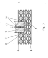
- FIG. 3 shows a high section through the axial center plane of the flame arrester arrangement 1, whereby the structure of the flame arrester arrangement 1 from alternately arranged turns of a smooth first metal strip 8 and provided with a defined corrugation (corrugation), a second metal strip 9 forming corrugated strip is illustrated. Furthermore, it becomes clear from the representation of FIG. 3 that cooling liquid 10 is introduced into the bore via a central bore 13 of the spark erosion electrode 7. The liquid is prevented in the axial direction by the sealingly arranged holding plates 5 at a drain, while in the circumferential direction of the affected by the bore column 11 between the first metal strip 8 and the second metal strip 9 are filled with liquid 10.
- the liquid can penetrate only to contact points 12 between the first metal strip 8 and the second metal strip 9 and is thus held in a defined space in the region of the bore 6. This ensures that the liquid is introduced into the bore 6 in a defined manner and exits the bore 6 on the outer circumference of the spark erosion electrode 7 again and can thus fulfill the function of cooling and discharging the eroded material required for EDM drilling.
- the bore 6 can be introduced in an analogous manner as in solid material, although the flame arrestor has the gap 11 forming axially open spaces.
Landscapes
- Engineering & Computer Science (AREA)
- Mechanical Engineering (AREA)
- Health & Medical Sciences (AREA)
- Public Health (AREA)
- Business, Economics & Management (AREA)
- Emergency Management (AREA)
- Physics & Mathematics (AREA)
- Thermal Sciences (AREA)
- Chemical & Material Sciences (AREA)
- Combustion & Propulsion (AREA)
- General Engineering & Computer Science (AREA)
- Electrical Discharge Machining, Electrochemical Machining, And Combined Machining (AREA)
- Spark Plugs (AREA)
- Gas Burners (AREA)
- Drilling And Boring (AREA)
- Control Of Combustion (AREA)
- Insulated Conductors (AREA)
- Perforating, Stamping-Out Or Severing By Means Other Than Cutting (AREA)
- Fireproofing Substances (AREA)
- Processing And Handling Of Plastics And Other Materials For Molding In General (AREA)
- Gas-Insulated Switchgears (AREA)
- Catalysts (AREA)
- Feeding, Discharge, Calcimining, Fusing, And Gas-Generation Devices (AREA)
- Winding, Rewinding, Material Storage Devices (AREA)
- Casting Support Devices, Ladles, And Melt Control Thereby (AREA)
- Connection Of Plates (AREA)
- Exhaust Gas After Treatment (AREA)
- Clamps And Clips (AREA)
Abstract
Description
- Die Erfindung betrifft ein Verfahren zum Einbringen von radial ausgerichteten Bohrungen für Fixierstifte in eine Flammensperranordnung, die aus zwei gemeinsam zu einer Scheibe mit einem etwa kreisförmigen Außenumfang gewickelten Metallbändern gebildet ist, von denen ein erstes Metallband ein glattes Band und das zweite Metallband ein eine definierte Riffelung aufweisendes Riffelband ist, wobei die beiden Bänder durch Aneinanderliegen definierte Spalte für einen Fluiddurchtritt bilden.
- Die Erfindung betrifft ferner eine Flammensperranordnung, die aus zwei gemeinsam zu einer Scheibe mit einem etwa kreisförmigen Außenumfang gewickelten Metallbändern gebildet ist, von denen ein erstes Metallband ein glattes Band und das zweite Metallband ein eine definierte Riffelung aufweisendes Riffelband ist, wobei die beiden Bänder durch Aneinanderliegen definierte Spalte für einen Fluiddurchtritt bilden und durch in radiale Bohrungen eingesetzte Fixierstifte zueinander in Position gehalten werden.
- Es sind seit langer Zeit Flammensperranordnungen bekannt, deren Fluiddurchtrittsspalte durch ein eine definierte Riffelung oder Wellung aufweisendes Riffelband in Verbindung mit einem das Riffelband beidseitig begrenzenden glatten Band gebildet werden. Die Herstellung derartiger Flammensperranordnungen gelingt dadurch, dass das glatte Band zusammen mit dem Riffelband gemeinsam spiralförmig aufgewickelt wird.
- Die für die Erstellung des Flammensperreinsatzes verwendeten Metallbänder müssen aus hochwarmfesten Edelstahl bestehen, nicht nur um die notwendige Temperaturbeständigkeit zu haben, sondern um auch für aggressive Medien widerstandsfähig zu sein, d.h. nicht zu korrodieren. Korrosionserscheinungen würden die definierten Fluiddurchtrittsspalte verändern und so ggf. ein Sicherheitsrisiko darstellen.
- Die mechanische Festigkeit von Flammensperren hängt vor allem vom Reibungswert der Metallbänder an den Kontaktstellen ab.
- Die verwendeten korrosionsbeständigen Materialien zeichnen sich regelmäßig durch eine sehr glatte, d.h. polierte, Oberfläche aus, sodass die Stabilität einer Flammensperre der hier in Frage stehenden Art, insbesondere bei größeren Durchmessern, aufgrund des relativ geringen Reibungswerts, ein Problem darstellen kann. Ggf. müssen besondere Vorrichtungen beschaffen werden, um die gewickelten Flammensperreinsätze in ein Gehäuse einbauen zu können, in dem die Einsätze stabil gehalten werden. Es ist bereits versucht worden, durch axial aufgelötete Verstärkungen die Stabilität der Flammensperreinsätze zu erhöhen. Hierdurch wird jedoch nicht nur der Aufwand höher, sondern auch die Handhabung sowohl bei der Herstellung als auch beim Warten der Flammensperren umständlicher.
- Es ist bekannt, in derartige Flammensperranordnungen von außen radiale Bohrungen einzubringen, die bis zu einem Wickelkern der Flammensperranordnung reichen können. Durch Einsetzen von Fixierstiften in diese Bohrungen wird eine radiale formschlüssige Verbindung zwischen den Bindungen der gewickelten Flammensperranordnung hergestellt. Je nach Größe der gewickelten Scheibe werden üblicherweise zwischen vier und acht Bohrungen mit Fixierstiften vorgesehen. Selbstverständlich ist es auch möglich, die Bohrungen durch den gesamten Durchmesser der Flammensperranordnung hindurchzutreiben.
- Auch beim vorsichtigen Eindringen der radialen Bohrungen in die Flammensperranordnung mittels eines Bohrers werden die Metallbänder im Bereich der Bohrungen verformt, sodass die Durchtrittsspalte der Flammensperranordnung im Bereich der radial eingebrachten Bohrungen bzw. der Fixierstifte verformt sind. Dadurch werden die vorgeschriebenen maximalen Nennweiten der Bohrungen nicht mehr sicher eingehalten, da die Verformungen unkontrolliert sind und daher zu Vergrößerungen der Spaltquerschnitte führen können. Durch einen vergrößerten Spaltquerschnitt kann es jedoch zu einem Flammendurchschlag durch die Flammensperre kommen, weil in dem vergrößerten Spaltquerschnitt keine ausreichende Abkühlung eines durchtretenden brennenden Gases mehr erfolgt, sodass die Flamme nicht sicher gelöscht wird.
- Die Verwendung der bekannten Flammensperranordnung, die durch in Bohrungen eingesetzte Fixierstifte zusammengehalten wird, ist daher zumindest für kritische Anwendungen beispielsweise bei hochexplosiblen Gasen nicht mit der erforderlichen Produktsicherheit möglich.
- Es sind daher andere Wege beschritten worden, Flammensperranordnungen zu stabilisieren, beispielsweise durch die Anbringung von aufgelöteten Verstärkungselementen o. ä.. Hierdurch wird der Aufwand - und damit der Preis - für die Flammensperranordnung jedoch erheblich erhöht.
- Der Erfindung liegt daher die Aufgabe zugrunde, eine formschlüssige Fixierung der Windungen einer gewickelten Flammensperranordnung zu ermöglichen, ohne Risiken für die Ausbildung der definierten Durchtrittsspalte eingehen zu müssen.
- Diese Aufgabe wird erfindungsgemäß mit einem Verfahren der eingangs erwähnten Art dadurch gelöst, dass die gewickelte Flammensperranordnung beidseitig axial vollständig mit Halteplatten abgeschlossen wird und dass vom Außenumfang radial nach innen mit einer Funkenerosionselektrode unter Eindrücken einer Kühlflüssigkeit die Bohrung eingebracht wird.
- Demgemäß wird die genannte Aufgabe mit einer Flammensperranordnung der eingangs erwähnten Art erfindungsgemäß dadurch gelöst, dass die Bohrungen durch Funkenerosion ohne Verformung der in das zweite Metallband eingeformten Riffelung eingebracht sind, sodass die Spalte auch im Bereich der Bohrungen in der durch die eingeformte Riffelung definierten Weise vorhanden sind.
- Die vorliegende Erfindung beruht auf der Erkenntnis, dass durch Funkenerosion die sich zu einer Bohrung ergänzenden Löcher auch in die dünnen Metallbänder eingebracht werden können, ohne die Metallbänder im Bereich der hergestellten Löcher zu verformen. Erfindungsgemäß ist daher vorgesehen, die für die Funkenerosion erforderliche Flüssigkeit, die zum Kühlen der Metallbänder und zum Abtransportieren des für die Bohrung erodierten Materials dient, in die axial offene Flammensperranordnung eingebracht werden kann, wenn die gewickelte Flammensperranordnung beidseitig axial vollständig mit Halteplatten abgeschlossen wird. Dadurch wird erreicht, dass sich im Bereich der hergestellten Bohrung ein geschlossener Flüssigkeitskreislauf ausbildet und die Flüssigkeit nicht undefiniert durch die axial offenen Spalte austritt.
- Dies ist die wesentliche verfahrenstechnische Voraussetzung dafür, das an sich nur für massive Materialien vorgesehene Funkenerosionsbohren nun erfindungsgemäß auch bei einer mit definierten Zwischenräumen gewickelten Flammensperranordnung anzuwenden.
- Erfindungsgemäß wird dabei eine Flammensperranordnung realisiert, deren Bohrungen die durch die Riffelung definierten Spalte nicht verändert, sodass die Fixierstifte zur formschlüssigen Verbindung der Bindungen der gewickelten Flammensperranordnung eingebracht werden können, ohne dass die Gefahr besteht, dass die kritischen Flammenspaltmaße verändert worden sind.
- Die erfindungsgemäße Flammensperranordnung ist vorzugsweise spiralförmig gewickelt. Grundsätzlich ist es jedoch auch möglich, die erfindungsgemäße Verstiftung der Wicklung auch einer Vielzahl von parallel gewickelten Metallbändern vorzusehen.
- Die Erfindung soll im Folgenden anhand der beigefügten Zeichnung erläutert werden. Es zeigen:
- Figur 1 -
- eine schematische Darstellung einer gewickelten Flammensperranordnung zwischen zwei Halteplatten beim Einbringen einer Bohrung mittels einer Funkenerosionselektrode;
- Figur 2 -
- ein vergrößertes Detail X aus Figur 1;
- Figur 3 -
- einen Querschnitt durch Windungen der gewickelten Flammensperranordnung im Bereich des Außenumfangs mit einer zur Herstellung einer Bohrung eingeführten Funkenerosionselektrode.
- Figur 1 zeigt eine Anordnung einer gewickelten Flammensperranordnung 1, die eine flache Scheibe mit einem etwa kreisförmigen Außenumfang bildet und durch eine Abschluss-Umfangslage 2 nach radial außen abgeschlossen sein kann. Die Flammensperranordnung 1 weist ein zentrales axiales Durchgangsloch 3 auf, durch das eine Halteachse 4 hindurchgesteckt ist, sodass die Flammensperranordnung 1 auf der Halteachse 4 drehbar gelagert ist.
- Für die Durchführung des erfindungsgemäßen Verfahrens ist die Flammensperranordnung 1 axial beidseitig mit jeweils einer Halteplatte 5 abgedichtet abgeschlossen.
- Figur 1 zeigt, dass zum Einbringen einer radialen Bohrung 6 in die Flammensperranordnung 1 eine Funkenerosionselektrode 7 vom Außenumfang her in die Flammensperranordnung eingeführt wird. Die Funkenerosionselektrode 7 treibt durch Funkenerosion Löcher in die gewickelten Lagen der Flammensperranordnung und so im Ergebnis die Bohrung 6 radial zum Zentrum der scheibenförmigen Flammensperranordnung 1 voran.
- Figur 2 verdeutlicht dies in einer vergrößerten Darstellung.
- Figur 3 zeigt einen Hochschnitt durch die axiale Mittenebene der Flammensperranordnung 1, wodurch der Aufbau der Flammensperranordnung 1 aus abwechselnd angeordneten Windungen eines glatten ersten Metallbandes 8 und eines mit einer definierten Riffelung (Wellung) versehenen, ein zweites Metallband 9 bildenden Riffelband verdeutlicht wird. Ferner wird aus der Darstellung der Figur 3 deutlich, dass über eine zentrale Bohrung 13 der Funkenerosionselektrode 7 Kühlflüssigkeit 10 in die Bohrung eingeleitet wird. Die Flüssigkeit wird in axialer Richtung durch die abgedichtet angeordneten Halteplatten 5 an einem Abfließen gehindert, während in Umfangsrichtung die von der Bohrung betroffenen Spalte 11 zwischen dem ersten Metallband 8 und dem zweiten Metallband 9 mit Flüssigkeit 10 gefüllt werden. Dabei kann die Flüssigkeit jedoch nur bis zu Kontaktpunkten 12 zwischen dem ersten Metallband 8 und dem zweiten Metallband 9 vordringen und wird somit in einem abgegrenzten Raum im Bereich der Bohrung 6 gehalten. Dadurch wird sichergestellt, dass die Flüssigkeit in definierter Weise in die Bohrung 6 eingeführt wird und aus der Bohrung 6 am Außenumfang der Funkenerosionselektrode 7 wieder austritt und so die für das Funkenerosionsbohren benötigte Funktion der Kühlung und des Abtransports des erodierten Materials erfüllen kann.
- Durch die erfindungsgemäßen Maßnahmen kann somit die Bohrung 6 in analoger Weise wie in massives Material eingebracht werden, obwohl die Flammensperranordnung die die Spalte 11 ausbildenden, axial offenen Zwischenräume aufweist.
- Es zeigt sich, dass die durch Funkenerosion eingebrachte Bohrung 6 zu keinerlei Veränderungen der Form der Riffelung des zweiten Metallbandes 9 oder des glatten ersten Metallbandes 8 führt, sodass die definierten Querschnitte der Spalte 11 der Flammensperranordnung 1 unverändert auch im Bereich der Bohrung 6 erhalten bleiben.
- In die fertig gestellten Bohrungen 6 werden dann passende Fixierstifte eingesetzt, sodass die Windungen der gewickelten Metallbänder 8, 9 nunmehr formschlüssig miteinander verbunden sind, sodass eine axiale Verschiebung der Windungen der Metallbänder 8, 9 nicht mehr möglich ist. Weitere Stabilisierungen der Flammensperranordnung 1 sind dann nicht mehr erforderlich.
Claims (2)
- Verfahren zum Einbringen von radial ausgerichteten Bohrungen (6) für Fixierstifte in eine Flammensperranordnung (1), die aus zwei gemeinsam zu einer Scheibe mit einem etwa kreisförmigen Außenumfang gewickelten Metallbändern (8, 9) gebildet ist, von denen ein erstes Metallband (8) ein glattes Band und das zweite Metallband (9) ein eine definierte Riffelung aufweisendes Riffelband ist, wobei die beiden Bänder (8, 9) durch Aneinanderliegen definierte Spalte (11) für einen Fluiddurchtritt bilden, dadurch gekennzeichnet, dass die gewickelte Flammensperranordnung (1) beidseitig axial vollständig mit Halteplatten (5) abgeschlossen wird und dass vom Außenumfang radial nach innen mit einer Funkenerosionselektrode (7) unter Eindrücken einer Kühlflüssigkeit (10) die Bohrung eingebracht wird.
- Flammensperranordnung, die aus zwei gemeinsam zu einer Scheibe mit einem etwa kreisförmigen Außenumfang gewickelten Metallbändern (8, 9) gebildet ist, von denen ein erstes Metallband (8) ein glattes Band und das zweite Metallband (9) ein eine definierte Riffelung aufweisendes Riffelband ist, wobei die beiden Bänder (8, 9) durch Aneinanderliegen definierte Spalte (11) für einen Fluiddurchtritt bilden und durch in radiale Bohrungen (6) eingesetzte Fixierstifte zueinander in Position gehalten werden, dadurch gekennzeichnet, dass die Bohrungen (6) durch Funkenerosion ohne Verformung der in das zweite Metallband eingeformten Riffelung eingebracht sind, sodass die Spalte (11) auch im Bereich der Bohrungen (6) in der durch die Riffelung definierten Weise vorhanden sind.
Priority Applications (3)
| Application Number | Priority Date | Filing Date | Title |
|---|---|---|---|
| SI200730171T SI1864695T1 (sl) | 2006-06-07 | 2007-04-19 | Komplet plamenske pregrade in postopek za vključitev vrtin v komplet plamenske pregrade |
| PL07007943T PL1864695T3 (pl) | 2006-06-07 | 2007-04-19 | Tłumik płomieni i sposób wykonywania otworów w tłumiku płomieni |
| CY20101100176T CY1109834T1 (el) | 2006-06-07 | 2010-02-24 | Φλογοπαγιδα και μεθοδος για την εισαγωγη οπων σε μια φλογοπαγιδα |
Applications Claiming Priority (1)
| Application Number | Priority Date | Filing Date | Title |
|---|---|---|---|
| DE102006026779A DE102006026779A1 (de) | 2006-06-07 | 2006-06-07 | Flammensperranordnung und Verfahren zum Einbringen von Bohrungen in eine Flammensperranordnung |
Publications (2)
| Publication Number | Publication Date |
|---|---|
| EP1864695A1 true EP1864695A1 (de) | 2007-12-12 |
| EP1864695B1 EP1864695B1 (de) | 2009-12-30 |
Family
ID=38231160
Family Applications (1)
| Application Number | Title | Priority Date | Filing Date |
|---|---|---|---|
| EP07007943A Active EP1864695B1 (de) | 2006-06-07 | 2007-04-19 | Flammensperranordnung und Verfahren zum Einbringen von Bohrungen in eine Flammensperranordnung |
Country Status (16)
| Country | Link |
|---|---|
| US (2) | US7955073B2 (de) |
| EP (1) | EP1864695B1 (de) |
| JP (1) | JP5128852B2 (de) |
| KR (1) | KR101216870B1 (de) |
| AT (1) | ATE453435T1 (de) |
| BR (1) | BRPI0702290B1 (de) |
| CA (1) | CA2590628C (de) |
| CY (1) | CY1109834T1 (de) |
| DE (2) | DE102006026779A1 (de) |
| DK (1) | DK1864695T3 (de) |
| ES (1) | ES2336709T3 (de) |
| NO (1) | NO20072400L (de) |
| PL (1) | PL1864695T3 (de) |
| PT (1) | PT1864695E (de) |
| SI (1) | SI1864695T1 (de) |
| TW (1) | TWI362952B (de) |
Families Citing this family (8)
| Publication number | Priority date | Publication date | Assignee | Title |
|---|---|---|---|---|
| CN104801801B (zh) * | 2015-04-30 | 2017-03-01 | 南京航空航天大学 | 基于低温环境的冰冻辅助微小孔加工方法及装置 |
| RU2646732C2 (ru) * | 2016-07-13 | 2018-03-06 | Ооо "Инарт" | Огнепреградитель |
| US20180056100A1 (en) | 2016-08-31 | 2018-03-01 | Emerson Process Management Regulator Technologies Tulsa, Llc | Method for Manufacturing a Flame Arrestor |
| US9987508B2 (en) | 2016-08-31 | 2018-06-05 | Emerson Process Management Regulator Technologies Tulsa, Llc | Hybrid composite flame cell |
| US10174941B2 (en) * | 2016-09-07 | 2019-01-08 | Selas Heat Technology Company Llc | Ribbon pack for gas burners |
| JP6534766B1 (ja) * | 2018-08-28 | 2019-06-26 | 株式会社ケーヒン | 吸気マニホールド |
| GB201816489D0 (en) | 2018-10-10 | 2018-11-28 | Elmac Tech Limited | Flame Arrester Element |
| USD1054527S1 (en) | 2022-02-12 | 2024-12-17 | Mark W Wyne | Flame arrestor |
Citations (2)
| Publication number | Priority date | Publication date | Assignee | Title |
|---|---|---|---|---|
| US2420599A (en) * | 1944-02-04 | 1947-05-13 | Shand And Jurs Company | Flame arrester |
| US2613144A (en) * | 1950-01-10 | 1952-10-07 | Orson A Carnahan | Backfire trap |
Family Cites Families (12)
| Publication number | Priority date | Publication date | Assignee | Title |
|---|---|---|---|---|
| US1896286A (en) * | 1929-01-23 | 1933-02-07 | Burns Bruce | Burner plate |
| JPS57121424A (en) * | 1981-01-19 | 1982-07-28 | Mitsubishi Electric Corp | Honeycomb structure machining method |
| EP0175054A1 (de) * | 1982-04-05 | 1986-03-26 | Rübeling, Günter | Verfahren zur Herstellung von Zahnersatzteilen |
| JPS6020138B2 (ja) * | 1982-06-14 | 1985-05-20 | 富士通株式会社 | 金属製ハニカム構造体の切断加工方法 |
| US4638139A (en) * | 1984-09-21 | 1987-01-20 | Rca Corporation | Electrical discharge machine cooling fluid containment apparatus |
| GB8612538D0 (en) * | 1986-05-22 | 1986-07-02 | Imi Amal Ltd | Flame arrester |
| JP3400839B2 (ja) * | 1994-01-11 | 2003-04-28 | 新日本製鐵株式会社 | 金属製触媒担体のワイヤ放電切断方法 |
| US6403910B1 (en) * | 1999-12-14 | 2002-06-11 | Hi-Tek Manufacturing, Inc. | EDM apparatus and method for performing EDM operation |
| US6389692B1 (en) * | 2000-12-15 | 2002-05-21 | General Electric Company | Method for removing stuck locking pin in turbine rotor |
| EP1437191A1 (de) * | 2003-01-13 | 2004-07-14 | Siemens Aktiengesellschaft | Verfahren zur Erzeugung eines Lochs |
| DE10336530B3 (de) * | 2003-08-05 | 2005-02-17 | Leinemann Gmbh & Co. | Flammendurchschlagsicherung |
| DE102006026510B3 (de) | 2006-06-06 | 2007-05-24 | Leinemann Gmbh & Co. Kg | Flammensperreinsatz und Verfahren zu seiner Herstellung |
-
2006
- 2006-06-07 DE DE102006026779A patent/DE102006026779A1/de not_active Withdrawn
-
2007
- 2007-04-19 EP EP07007943A patent/EP1864695B1/de active Active
- 2007-04-19 AT AT07007943T patent/ATE453435T1/de active
- 2007-04-19 DE DE502007002460T patent/DE502007002460D1/de active Active
- 2007-04-19 PT PT07007943T patent/PT1864695E/pt unknown
- 2007-04-19 DK DK07007943.9T patent/DK1864695T3/da active
- 2007-04-19 ES ES07007943T patent/ES2336709T3/es active Active
- 2007-04-19 PL PL07007943T patent/PL1864695T3/pl unknown
- 2007-04-19 SI SI200730171T patent/SI1864695T1/sl unknown
- 2007-04-25 TW TW096114554A patent/TWI362952B/zh active
- 2007-05-09 NO NO20072400A patent/NO20072400L/no not_active Application Discontinuation
- 2007-05-17 BR BRPI0702290-5A patent/BRPI0702290B1/pt active IP Right Grant
- 2007-05-24 US US11/753,243 patent/US7955073B2/en active Active
- 2007-05-28 CA CA2590628A patent/CA2590628C/en active Active
- 2007-05-31 JP JP2007144300A patent/JP5128852B2/ja active Active
- 2007-06-05 KR KR1020070055040A patent/KR101216870B1/ko active Active
-
2009
- 2009-12-10 US US12/635,047 patent/US7959434B2/en active Active
-
2010
- 2010-02-24 CY CY20101100176T patent/CY1109834T1/el unknown
Patent Citations (2)
| Publication number | Priority date | Publication date | Assignee | Title |
|---|---|---|---|---|
| US2420599A (en) * | 1944-02-04 | 1947-05-13 | Shand And Jurs Company | Flame arrester |
| US2613144A (en) * | 1950-01-10 | 1952-10-07 | Orson A Carnahan | Backfire trap |
Also Published As
| Publication number | Publication date |
|---|---|
| ATE453435T1 (de) | 2010-01-15 |
| ES2336709T3 (es) | 2010-04-15 |
| BRPI0702290A (pt) | 2008-02-19 |
| JP5128852B2 (ja) | 2013-01-23 |
| US7955073B2 (en) | 2011-06-07 |
| PL1864695T3 (pl) | 2010-05-31 |
| TW200800325A (en) | 2008-01-01 |
| CA2590628C (en) | 2013-06-18 |
| CY1109834T1 (el) | 2014-09-10 |
| DE502007002460D1 (de) | 2010-02-11 |
| CA2590628A1 (en) | 2007-12-07 |
| DE102006026779A1 (de) | 2007-12-20 |
| SI1864695T1 (sl) | 2010-03-31 |
| JP2007326210A (ja) | 2007-12-20 |
| US7959434B2 (en) | 2011-06-14 |
| KR20070117475A (ko) | 2007-12-12 |
| NO20072400L (no) | 2007-12-10 |
| DK1864695T3 (da) | 2010-03-22 |
| BRPI0702290B1 (pt) | 2020-06-30 |
| EP1864695B1 (de) | 2009-12-30 |
| TWI362952B (en) | 2012-05-01 |
| US20100083479A1 (en) | 2010-04-08 |
| KR101216870B1 (ko) | 2012-12-28 |
| US20080176177A1 (en) | 2008-07-24 |
| PT1864695E (pt) | 2010-01-29 |
Similar Documents
| Publication | Publication Date | Title |
|---|---|---|
| EP1864695B1 (de) | Flammensperranordnung und Verfahren zum Einbringen von Bohrungen in eine Flammensperranordnung | |
| DE69608350T2 (de) | Schraubverbindung für Rohre | |
| EP0169402B1 (de) | Gesteinsbohrer | |
| DE2640458C3 (de) | Druckreduzierventil | |
| EP2662124B1 (de) | Trennvorrichtung für rohrförmige Durchflussvorrichtungen | |
| EP2260906B1 (de) | Flammensperranordnung | |
| EP2829804B1 (de) | Brennkammerschindel einer Gasturbine sowie Verfahren zu deren Herstellung | |
| DE2241273C2 (de) | Biegsame Dichtung aus Metall | |
| DE10119534A1 (de) | Metallische Dichtung | |
| EP1864694B1 (de) | Flammensperreinsatz und Verfahren zu seiner Herstellung | |
| DE1501585C3 (de) | Regenerativ-Wärmetauscher | |
| DE19810713C2 (de) | Kernbohrvorrichtung, Vorrichtung zum Einstecken in ein Kronenrohr und Verfahren zur Kühlung einer Bohrstelle | |
| DE3319717A1 (de) | Bohrkopf fuer einen mehrteiligen erdbohrer | |
| DE102007000143A1 (de) | Acetylen-Manometer mit Schutzdrossel | |
| EP2801725B1 (de) | Vorrichtung mit mindestens einem Kanal zum Führen eines gasförmigen oder flüssigen Betriebsmittels | |
| EP0281685A1 (de) | Als Kompensator wirkender, rohrförmiger Faltenbalg | |
| DE3036398C2 (de) | Schutzvorrichtung für bruchgefährdete Abschnitte von Rohrleitungen | |
| DE102017108270B4 (de) | Dichtungskassette für einen Injektor einer Verbrennungskraftmaschine und Injektoranordnung für eine Verbrennungskraftmaschine | |
| DE102007050498B4 (de) | Verfahren zur Herstellung von Schlitzen in der Bodenwand einer napfförmigen Hülsenanordnung | |
| EP4506597B1 (de) | Semimetalldichtung | |
| DE2622457C3 (de) | Rollenlagerung | |
| EP1378706A1 (de) | Flanschverbindung sowie Verfahren zum Montieren einer solchen Flanschverbindung | |
| DE102020004451B3 (de) | Verfahren zur Herstellung eines Ventils | |
| EP1177397A1 (de) | Schlauch mit gewellter innenfläche und einschubteil | |
| DE1491421A1 (de) | Elektronenstrahlroehre mit mehreren Resonanzhohlraeumen und Verfahren zur Herstellung derselben |
Legal Events
| Date | Code | Title | Description |
|---|---|---|---|
| PUAI | Public reference made under article 153(3) epc to a published international application that has entered the european phase |
Free format text: ORIGINAL CODE: 0009012 |
|
| 17P | Request for examination filed |
Effective date: 20070804 |
|
| AK | Designated contracting states |
Kind code of ref document: A1 Designated state(s): AT BE BG CH CY CZ DE DK EE ES FI FR GB GR HU IE IS IT LI LT LU LV MC MT NL PL PT RO SE SI SK TR |
|
| AX | Request for extension of the european patent |
Extension state: AL BA HR MK YU |
|
| AKX | Designation fees paid |
Designated state(s): AT BE BG CH CY CZ DE DK EE ES FI FR GB GR HU IE IS IT LI LT LU LV MC MT NL PL PT RO SE SI SK TR |
|
| GRAP | Despatch of communication of intention to grant a patent |
Free format text: ORIGINAL CODE: EPIDOSNIGR1 |
|
| GRAS | Grant fee paid |
Free format text: ORIGINAL CODE: EPIDOSNIGR3 |
|
| GRAA | (expected) grant |
Free format text: ORIGINAL CODE: 0009210 |
|
| AK | Designated contracting states |
Kind code of ref document: B1 Designated state(s): AT BE BG CH CY CZ DE DK EE ES FI FR GB GR HU IE IS IT LI LT LU LV MC MT NL PL PT RO SE SI SK TR |
|
| REG | Reference to a national code |
Ref country code: GB Ref legal event code: FG4D Free format text: NOT ENGLISH |
|
| REG | Reference to a national code |
Ref country code: CH Ref legal event code: NV Representative=s name: BRAUNPAT BRAUN EDER AG Ref country code: CH Ref legal event code: EP |
|
| REG | Reference to a national code |
Ref country code: IE Ref legal event code: FG4D |
|
| REG | Reference to a national code |
Ref country code: PT Ref legal event code: SC4A Free format text: AVAILABILITY OF NATIONAL TRANSLATION Effective date: 20100122 |
|
| REF | Corresponds to: |
Ref document number: 502007002460 Country of ref document: DE Date of ref document: 20100211 Kind code of ref document: P |
|
| REG | Reference to a national code |
Ref country code: DK Ref legal event code: T3 |
|
| REG | Reference to a national code |
Ref country code: RO Ref legal event code: EPE |
|
| REG | Reference to a national code |
Ref country code: NL Ref legal event code: T3 |
|
| REG | Reference to a national code |
Ref country code: ES Ref legal event code: FG2A Ref document number: 2336709 Country of ref document: ES Kind code of ref document: T3 |
|
| REG | Reference to a national code |
Ref country code: GR Ref legal event code: EP Ref document number: 20100400506 Country of ref document: GR |
|
| REG | Reference to a national code |
Ref country code: PL Ref legal event code: T3 |
|
| REG | Reference to a national code |
Ref country code: SK Ref legal event code: T3 Ref document number: E 6913 Country of ref document: SK |
|
| REG | Reference to a national code |
Ref country code: HU Ref legal event code: AG4A Ref document number: E008060 Country of ref document: HU |
|
| PLBE | No opposition filed within time limit |
Free format text: ORIGINAL CODE: 0009261 |
|
| STAA | Information on the status of an ep patent application or granted ep patent |
Free format text: STATUS: NO OPPOSITION FILED WITHIN TIME LIMIT |
|
| 26N | No opposition filed |
Effective date: 20101001 |
|
| PG25 | Lapsed in a contracting state [announced via postgrant information from national office to epo] |
Ref country code: IT Free format text: LAPSE BECAUSE OF NON-PAYMENT OF DUE FEES Effective date: 20100419 |
|
| PGFP | Annual fee paid to national office [announced via postgrant information from national office to epo] |
Ref country code: LU Payment date: 20110420 Year of fee payment: 5 |
|
| PGFP | Annual fee paid to national office [announced via postgrant information from national office to epo] |
Ref country code: CH Payment date: 20110421 Year of fee payment: 5 Ref country code: SE Payment date: 20110419 Year of fee payment: 5 Ref country code: PT Payment date: 20110411 Year of fee payment: 5 Ref country code: MC Payment date: 20110419 Year of fee payment: 5 Ref country code: GR Payment date: 20110426 Year of fee payment: 5 Ref country code: IE Payment date: 20110415 Year of fee payment: 5 Ref country code: IS Payment date: 20110420 Year of fee payment: 5 Ref country code: LT Payment date: 20110412 Year of fee payment: 5 Ref country code: LV Payment date: 20110421 Year of fee payment: 5 |
|
| PGFP | Annual fee paid to national office [announced via postgrant information from national office to epo] |
Ref country code: SK Payment date: 20110418 Year of fee payment: 5 Ref country code: RO Payment date: 20110418 Year of fee payment: 5 Ref country code: SI Payment date: 20110407 Year of fee payment: 5 Ref country code: BG Payment date: 20110426 Year of fee payment: 5 Ref country code: EE Payment date: 20110425 Year of fee payment: 5 Ref country code: FI Payment date: 20110418 Year of fee payment: 5 |
|
| PGFP | Annual fee paid to national office [announced via postgrant information from national office to epo] |
Ref country code: CY Payment date: 20110308 Year of fee payment: 5 |
|
| PGFP | Annual fee paid to national office [announced via postgrant information from national office to epo] |
Ref country code: MT Payment date: 20110314 Year of fee payment: 5 |
|
| REG | Reference to a national code |
Ref country code: PT Ref legal event code: MM4A Free format text: LAPSE DUE TO NON-PAYMENT OF FEES Effective date: 20121019 |
|
| REG | Reference to a national code |
Ref country code: LT Ref legal event code: MM4D Effective date: 20120419 |
|
| PG25 | Lapsed in a contracting state [announced via postgrant information from national office to epo] |
Ref country code: MC Free format text: LAPSE BECAUSE OF NON-PAYMENT OF DUE FEES Effective date: 20120430 |
|
| REG | Reference to a national code |
Ref country code: CH Ref legal event code: PL |
|
| REG | Reference to a national code |
Ref country code: SE Ref legal event code: EUG |
|
| REG | Reference to a national code |
Ref country code: EE Ref legal event code: MM4A Ref document number: E004163 Country of ref document: EE Effective date: 20120430 |
|
| REG | Reference to a national code |
Ref country code: SK Ref legal event code: MM4A Ref document number: E 6913 Country of ref document: SK Effective date: 20120419 |
|
| REG | Reference to a national code |
Ref country code: IE Ref legal event code: MM4A |
|
| REG | Reference to a national code |
Ref country code: GR Ref legal event code: ML Ref document number: 20100400506 Country of ref document: GR Effective date: 20121102 |
|
| PG25 | Lapsed in a contracting state [announced via postgrant information from national office to epo] |
Ref country code: SK Free format text: LAPSE BECAUSE OF NON-PAYMENT OF DUE FEES Effective date: 20120419 Ref country code: CH Free format text: LAPSE BECAUSE OF NON-PAYMENT OF DUE FEES Effective date: 20120430 Ref country code: FI Free format text: LAPSE BECAUSE OF NON-PAYMENT OF DUE FEES Effective date: 20120419 Ref country code: IS Free format text: LAPSE BECAUSE OF FAILURE TO SUBMIT A TRANSLATION OF THE DESCRIPTION OR TO PAY THE FEE WITHIN THE PRESCRIBED TIME-LIMIT Effective date: 20121031 Ref country code: LT Free format text: LAPSE BECAUSE OF NON-PAYMENT OF DUE FEES Effective date: 20120419 Ref country code: LI Free format text: LAPSE BECAUSE OF NON-PAYMENT OF DUE FEES Effective date: 20120430 Ref country code: CY Free format text: LAPSE BECAUSE OF NON-PAYMENT OF DUE FEES Effective date: 20120419 Ref country code: IE Free format text: LAPSE BECAUSE OF NON-PAYMENT OF DUE FEES Effective date: 20120419 Ref country code: EE Free format text: LAPSE BECAUSE OF NON-PAYMENT OF DUE FEES Effective date: 20120430 |
|
| REG | Reference to a national code |
Ref country code: SI Ref legal event code: KO00 Effective date: 20121224 |
|
| PG25 | Lapsed in a contracting state [announced via postgrant information from national office to epo] |
Ref country code: SE Free format text: LAPSE BECAUSE OF NON-PAYMENT OF DUE FEES Effective date: 20120420 Ref country code: LV Free format text: LAPSE BECAUSE OF NON-PAYMENT OF DUE FEES Effective date: 20120419 Ref country code: SI Free format text: LAPSE BECAUSE OF NON-PAYMENT OF DUE FEES Effective date: 20120420 Ref country code: PT Free format text: LAPSE BECAUSE OF NON-PAYMENT OF DUE FEES Effective date: 20121019 Ref country code: GR Free format text: LAPSE BECAUSE OF NON-PAYMENT OF DUE FEES Effective date: 20121102 |
|
| PG25 | Lapsed in a contracting state [announced via postgrant information from national office to epo] |
Ref country code: RO Free format text: LAPSE BECAUSE OF NON-PAYMENT OF DUE FEES Effective date: 20120419 |
|
| PG25 | Lapsed in a contracting state [announced via postgrant information from national office to epo] |
Ref country code: BG Free format text: LAPSE BECAUSE OF NON-PAYMENT OF DUE FEES Effective date: 20121231 Ref country code: MT Free format text: LAPSE BECAUSE OF FAILURE TO SUBMIT A TRANSLATION OF THE DESCRIPTION OR TO PAY THE FEE WITHIN THE PRESCRIBED TIME-LIMIT Effective date: 20130430 |
|
| PG25 | Lapsed in a contracting state [announced via postgrant information from national office to epo] |
Ref country code: LU Free format text: LAPSE BECAUSE OF NON-PAYMENT OF DUE FEES Effective date: 20120419 |
|
| REG | Reference to a national code |
Ref country code: DE Ref legal event code: R082 Ref document number: 502007002460 Country of ref document: DE Representative=s name: GRAMM, LINS & PARTNER PATENT- UND RECHTSANWAEL, DE |
|
| REG | Reference to a national code |
Ref country code: FR Ref legal event code: PLFP Year of fee payment: 10 |
|
| REG | Reference to a national code |
Ref country code: FR Ref legal event code: PLFP Year of fee payment: 11 |
|
| REG | Reference to a national code |
Ref country code: FR Ref legal event code: PLFP Year of fee payment: 12 |
|
| PG25 | Lapsed in a contracting state [announced via postgrant information from national office to epo] |
Ref country code: MT Free format text: LAPSE BECAUSE OF FAILURE TO SUBMIT A TRANSLATION OF THE DESCRIPTION OR TO PAY THE FEE WITHIN THE PRESCRIBED TIME-LIMIT Effective date: 20120419 |
|
| PGFP | Annual fee paid to national office [announced via postgrant information from national office to epo] |
Ref country code: NL Payment date: 20250422 Year of fee payment: 19 |
|
| PGFP | Annual fee paid to national office [announced via postgrant information from national office to epo] |
Ref country code: DE Payment date: 20250428 Year of fee payment: 19 Ref country code: PL Payment date: 20250407 Year of fee payment: 19 |
|
| PGFP | Annual fee paid to national office [announced via postgrant information from national office to epo] |
Ref country code: ES Payment date: 20250519 Year of fee payment: 19 Ref country code: DK Payment date: 20250423 Year of fee payment: 19 |
|
| PGFP | Annual fee paid to national office [announced via postgrant information from national office to epo] |
Ref country code: HU Payment date: 20250423 Year of fee payment: 19 |
|
| PGFP | Annual fee paid to national office [announced via postgrant information from national office to epo] |
Ref country code: BE Payment date: 20250422 Year of fee payment: 19 Ref country code: IT Payment date: 20250430 Year of fee payment: 19 |
|
| PGFP | Annual fee paid to national office [announced via postgrant information from national office to epo] |
Ref country code: FR Payment date: 20250428 Year of fee payment: 19 |
|
| PGFP | Annual fee paid to national office [announced via postgrant information from national office to epo] |
Ref country code: AT Payment date: 20250416 Year of fee payment: 19 |
|
| PGFP | Annual fee paid to national office [announced via postgrant information from national office to epo] |
Ref country code: TR Payment date: 20250410 Year of fee payment: 19 |
|
| PGFP | Annual fee paid to national office [announced via postgrant information from national office to epo] |
Ref country code: CZ Payment date: 20250404 Year of fee payment: 19 |
|
| PGFP | Annual fee paid to national office [announced via postgrant information from national office to epo] |
Ref country code: GB Payment date: 20260324 Year of fee payment: 20 |