EP1867496B1 - Pneumatique - Google Patents
Pneumatique Download PDFInfo
- Publication number
- EP1867496B1 EP1867496B1 EP06711511A EP06711511A EP1867496B1 EP 1867496 B1 EP1867496 B1 EP 1867496B1 EP 06711511 A EP06711511 A EP 06711511A EP 06711511 A EP06711511 A EP 06711511A EP 1867496 B1 EP1867496 B1 EP 1867496B1
- Authority
- EP
- European Patent Office
- Prior art keywords
- tire
- tread
- groove
- step portion
- lug
- Prior art date
- Legal status (The legal status is an assumption and is not a legal conclusion. Google has not performed a legal analysis and makes no representation as to the accuracy of the status listed.)
- Expired - Lifetime
Links
Images



Classifications
-
- B—PERFORMING OPERATIONS; TRANSPORTING
- B60—VEHICLES IN GENERAL
- B60C—VEHICLE TYRES; TYRE INFLATION; TYRE CHANGING; CONNECTING VALVES TO INFLATABLE ELASTIC BODIES IN GENERAL; DEVICES OR ARRANGEMENTS RELATED TO TYRES
- B60C11/00—Tyre tread bands; Tread patterns; Anti-skid inserts
- B60C11/03—Tread patterns
- B60C11/0311—Patterns comprising tread lugs arranged parallel or oblique to the axis of rotation
-
- B—PERFORMING OPERATIONS; TRANSPORTING
- B60—VEHICLES IN GENERAL
- B60C—VEHICLE TYRES; TYRE INFLATION; TYRE CHANGING; CONNECTING VALVES TO INFLATABLE ELASTIC BODIES IN GENERAL; DEVICES OR ARRANGEMENTS RELATED TO TYRES
- B60C11/00—Tyre tread bands; Tread patterns; Anti-skid inserts
- B60C11/03—Tread patterns
- B60C11/0311—Patterns comprising tread lugs arranged parallel or oblique to the axis of rotation
- B60C11/0316—Patterns comprising tread lugs arranged parallel or oblique to the axis of rotation further characterised by the groove cross-section
-
- B—PERFORMING OPERATIONS; TRANSPORTING
- B60—VEHICLES IN GENERAL
- B60C—VEHICLE TYRES; TYRE INFLATION; TYRE CHANGING; CONNECTING VALVES TO INFLATABLE ELASTIC BODIES IN GENERAL; DEVICES OR ARRANGEMENTS RELATED TO TYRES
- B60C2200/00—Tyres specially adapted for particular applications
- B60C2200/06—Tyres specially adapted for particular applications for heavy duty vehicles
- B60C2200/065—Tyres specially adapted for particular applications for heavy duty vehicles for construction vehicles
Definitions
- the present invention relates to a pneumatic tire for heavy load, and more particularly, to a pneumatic tire capable of enhancing the biased abrasion resistance of a tread.
- Patent Document 1 Japanese Patent Application Laid-open No. 2000-264022
- Patent Document 2 Japanese Patent Application Laid-open No. 2001-39124 JP61060308 discloses a known pneumatic tire, according to the preamble of claim 1.
- the biased abrasion not only deteriorates outward appearance, but also increases the volume of rubber to be worn and thus, the abrasion resistance is deteriorated.
- the lug groove at the most worn portion is made shallow, and the rigidity of the land portion is increased.
- the deformation of the land portion is suppressed, since a force which becomes burden on the land portion is also increased, sufficient effect can not be obtained, and since the volume of the tread rubber is increased, the temperature of the tire during running is increased, and the durability is deteriorated.
- the present inventor studied very hard from two view points, that is, a force acting in a widthwise direction of the tire and a force acting in a circumferential direction of the tire concerning abrasion of the tread and deformation of the land portion.
- the force acting in the widthwise direction of the tire is mainly caused by a slip in a direction orthogonal to a tire equatorial plane generated between the tread side of the tire and the road surface, and in an outward direction in the widthwise direction of the tire, and that in a pattern having the lug groove, there is a powerful tendency that a slip between the tread side of the tire and the road surface is generated in a direction orthogonal to a lug groove wall.
- a pneumatic tire having lug grooves arranged in a tread in a direction intersecting with a circumferential direction of the tire and in the circumferential direction of the tire, and land portions divided by the lug grooves, in which when a distance from a ground-contact end to a tire equatorial plane in a state where the tire is assembled to a normal rim and a normal internal pressure is charged into the tire and a normal load is applied to the tire is defined as L, in a region where a distance from the tire equatorial plane to an axial outer side of the tire is in a range of from 0.45L to 0.55L, a step portion which is a boundary between a tread side groove wall and a tire center side groove wall is provided respectively on both sides of the lug groove, an average groove width at the tread side of the step portions is widened toward an axial outer side of the tire and the width of the step portion is increased toward the axial outer side of the tire, and the tread side groove walls
- a ground-contact pressure is concentrated because a belt width is narrow. For this reason, there is a tendency that in the region on the land portion of from 0.45L to 0.55L from the tire equatorial plane to the axial outer side of the tire (intermediate point between the tire equatorial plane and the ground-contact end, i.e., so-called 1/4 point), the kicking end has a greater slip toward the axial outer side of the tire than that of the tread-in end, and the abrasion amount thereof is greater.
- the component toward an axial inner side of the tire which is opposite from the axial outer side of the tire is added to the force applied to the kicking end of the land portion and with this, the abrasion of the kicking end can be moderated, and it is possible to improve the phenomenon (biased abrasion and heel-and-toe abrasion in the circumferential direction of the tire) in which the difference in abrasion amount between the tread-in end and the kicking end is increased.
- the abrasion amount of the kicking end of the land portion is suppressed, the concentration of ground-contact pressure near the kicking end is improved and as a result, the abrasion amount at the axial outer side of the tire from the 1/4 point is reduced and the biased abrasion in the tire width direction is also improved.
- the groove wall of the lug groove is provided with the step portion, the tread side groove width at the tread side of the step portion is widened toward the axial outer side of the tire, and the width of the step portion is increased toward the axial outer side of the tire. Therefore, in a portion of the land portion where the ground-contact length near the ground-contact end is short, deformation of the land portion can be suppressed by the enhanced rigidity of the skirt of the land portion, deformation of the land portion can be absorbed by the step portion, and lift from the road surface at the tread-in end of the land portion can be suppressed. Even in a portion of the land portion where the ground-contact length near the tire equatorial plane is long, the volume of the lug groove can sufficiently be secured, (the volume of the tread rubber is not excessively increased), and heat radiation ability and drainage ability can be maintained.
- the "normal rim” means a standard rim having an appropriate size defined in the YEAR BOOK of 2004 issued by JATMA
- the "normal load” and the “normal internal pressure” are the maximum load and air pressure against the maximum load in an appropriate size and ply rating defined in the YEAR BOOK of 2004 issued by JATMA.
- a circumferential groove extending in the circumferential direction of the tire is formed in a region on the tread where a distance from the tire equatorial plane to the axial outer side of the tire is in a range of from 0.55L to 0.70L.
- the present inventor conducted research concerning a relation between a slip between the tread side and the road surface and an angle formed between the groove wall of the lug groove and the axial direction of the tire. As a result, it was found that not only the 1/4 point where the abrasion amount was great, but also the angle of the lug groove near the ground-contact end, greatly influence the generation of the biased abrasion, and that, depending upon the angle, the influence of deformation of the land portion near the ground-contact end is exerted to the vicinity of the 1/4 point, and the biased abrasion suppressing effect is deteriorated.
- the circumferential groove extending in the circumferential direction of the tire is formed in the region where a distance from the tire equatorial plane to the axial outer side of the tire is in a range of from 0.55L to 0.70L. Therefore, influence of the lug groove angle near the ground-contact end exerted on the biased abrasion suppressing effect can be eliminated, and the effect of the lug groove of claim 1 can be maximized.
- the reason why the position where the circumferential groove is formed is set to the region of from 0.55L to 0.70L from the tire equatorial plane to the axial outer side of the tire is that if the distance is less than 0.55L, the rigidity near the circumferential groove is lowered and the biased abrasion resistance is deteriorated, and if the distance exceeds 0.70L, the effect of the circumferential groove is not easily transmitted to the 1/4 point (the region between the circumferential groove and the tire equatorial plane is widened, and in the region, the influence of deformation of the land portion near the ground-contact end is exerted to the 1/4 point), and the influence of the lug groove angle near the ground-contact end exerted on the biased abrasion suppressing effect can not be eliminated.
- the groove width of the circumferential groove is in a range of from 0.01L to 0.1L with respect to the distance L from the tire equatorial plane to the ground-contact end, and that the groove depth of the circumferential groove is in a range of from 20 to 60% of the groove depth of the lug groove.
- a depth position where the step portion is formed is a position of from 0.3 to 0.7 times of a groove depth of the lug groove from the tread side to the tire center side.
- the reason why the depth position of the step portion is set to the range from 0.3 to 0.7 times of the groove depth of the lug groove from the tread side to the tire center side is that if the depth position exceeds 0.7 times, the step portion is excessively close to the bottom of the lug groove and the step portion is too far from the tread side and the biased abrasion suppressing effect is deteriorated, and if the depth position is less than 0.3 times, the step portion is too close to the tread side, the step portion disappears soon by abrasion of the tread and thus, the effect continuation time of the step portion becomes short.
- the effect of the step portion can be exhibited most effectively by appropriately setting the distance from the tread side to the step portion.
- an angle formed between the step portion and the tread side groove wall connected to the step portion is in a range of from 70° to 120°.
- the reason why the angle formed between the step portion and the tread side groove wall connected to the step portion is in a range of from 70° to 120° is that if the angle is less than 70°, the durability with respect to the land portion wrench or the like is deteriorated, and if the angle exceeds 120°, the land portion deformation absorbing effect by the step portion is reduced.
- the pneumatic tire of the invention has excellent effect that in the pneumatic tire for heavy load, the biased abrasion resistance of the tread can be enhanced while the durability of the tire being maintained.
- Fig. 1A is a diagram showing a tread pattern of a pneumatic tire according to a first embodiment
- a pneumatic tire 10 of the present embodiment includes lug grooves 14 formed in a tread 12 arranged in a direction intersecting with a circumferential direction of the tire and in the circumferential direction of the tire, and land portions 16 divided by the lug grooves 14.
- a center rib 24 connected to the land portions 16 is provided at a tire equatorial plane CL.
- the lug grooves 14 terminate at the side of the tire equatorial plane CL without penetrating the center rib 24, and is formed up to at least a ground-contact end 18 at the axial outer side of the tire.
- Thin grooves for connecting the lug grooves 14 while interposing the tire equatorial plane CL therebetween may be arranged in the center rib 24.
- Step portions 22 are provided on the pneumatic tire 10.
- the step portions 22 are boundaries between tread side groove walls 20A and tire center side groove walls 20B.
- the step portions 22 are provided on opposite groove walls 20 of the lug groove 14 in a region 40 where a distance from the tire equatorial plane CL toward the axial outer side of the tire is from 0.45L to 0.55L if a distance from the ground-contact end 18 to the tire equatorial plane CL is defined as L when the tire is assembled to a normal rim and a normal internal pressure is charged into the tire and a normal load is applied.
- the reason why the range of the region 40 is set such that the distance from the tire equatorial plane CL toward the axial outer side of the tire is from 0.45L to 0.55L is that a biased abrasion resistance in the vicinity of an intermediate point between the tire equatorial plane CL and the ground-contact end 18, i.e., in the vicinity of a so-called 1/4 point is caused to be enhanced.
- Positions of from 0.45L and 0.55L from the tire equatorial plane CL in Fig. 1A are exaggerated for purposes of illustration, and the positions 0.45L and 0.55L from the tire equatorial plane CL are much closer as can be found from its size ratio.
- a cross-sectional shape of the step portion 22 is step-shaped, but the cross section may have such a shape that corners between the step portion 22 and the tread side groove wall 20A have a curvature as shown in Fig. 1C . This is because that if the step portion 22 has the curvature, a crack is not easily generated in the corners.
- both the tread side groove wall 20A and the tire center side groove wall 20B of the lug groove 14 are formed such that their groove widths are increased from the groove bottom toward the tread side 12A.
- the average groove width WA in the tread side groove wall 20A of the step portion 22 is widened toward the axial outer side of the tire, and the width WS of the step portion 22 is increased toward the axial outer side.
- the tread side groove walls 20A at a tread-in end 16A and at a kicking end 16B of the land portion 16 are respectively inclined in opposite directions at angles ⁇ with respect to the tire axial direction.
- tread-in end 16A is a tread side edge in tread side groove wall 20A at the tread-side
- the kicking end 16B is a tread side edge in the tread side groove wall 20A at the kicking side.
- the average groove width WB at the tire center side of the step portion 22 is not changed almost at all in the region 40, but since the average groove width WA is widened toward the axial outer side of the tire, a difference between the average groove width WA and the average groove width WB is increased and the width WS of the step portion 22 is increased with an amount of the difference correspondingly.
- the average groove width WB of the lug groove 14 is slightly narrowed toward the axial outer side of the tire, the average groove width WA is substantially constant, and the width WS of the step portion 22 is slightly increased.
- the shape of the lug groove 14 in the region 50 is not limited to this.
- a depth position where the step portion 22 is formed is a position of from 0.3 to 0.7 times of a groove depth of the lug groove 14 from the tread side 12A to the tire center side.
- the reason why the depth position of the step portion 22 is set in this range is that if the depth position exceeds 0.7 times, the step portion 22 is excessively close to the bottom of the lug groove 14 and the step portion 22 is too far from the tread side 12A and the biased abrasion suppressing effect is deteriorated, and if the depth position is less than 0.3 times, the step portion 22 is too close to the tread side 12A, the step portion 22 will disappear soon by abrasion of the tread 12 and thus, the effect continuation time of the step portion 22 becomes short.
- the step portion 22 is illustrated in a direction which is tangent to the circumferential direction of the tire, but if the step portion 22 is inclined in a direction different from this direction, a boundary between the tread side groove wall 20A and the step portion 22 is set to be the depth position of the step portion 22.
- the boundary between the step portion 22 and the tire center side groove wall 20B is set to be the depth position of the step portion.
- an angle ⁇ formed between the step portion 22 and the tread side groove wall 20A which is continuous with the step portion 22 is in a range of from 70° to 120°.
- the reason why the angle ⁇ is set in this range is that if the angle is less than 70°, the durability with respect to the land portion wrench is deteriorated, and if the angle exceeds 120°, the deformation absorbing effect of the land portion 16 by the step portion 22 is reduced.
- the step portion 22 is formed by projecting the tire center side groove wall 20B from, as a reference, the tread side groove wall 20A (by widening the skirt), and the tread side groove wall 20A and the tire center side groove wall 20B are substantially in parallel to each other.
- the above numeric value range of the angle ⁇ shows a range of inclination angle of the step portion 22 when the tread side groove wall 20A and the tire center side groove wall 20B are substantially in parallel to each other.
- the average groove width WA of the lug groove 14 at the side of the tread side 12A in this embodiment is widened toward the axial outer side of the tire in the region 40, the direction of the slip at the tread-in end 16A is in the outer direction of the tire, and the slip at the kicking end 16B is in the inner direction of the tire.
- the tread-in end 16A has a component Fout in the outer direction of the tire
- the kicking end 16B has a component Fin in the inner direction of the tire.
- the kicking end 16B has a greater slip in the outer direction of the tire which may cause the abrasion because a ground-contact pressure concentrates, as compared with the tread-in end 16A.
- the component Fin in the inner direction of the tire is added in the kicking end 16B and the component Fout in the outer direction of the tire is added in the tread-in end 16A, and thus, the abrasion of the tread-in end 16A is accelerated, and the abrasion of the kicking end 16B is suppressed.
- the biased abrasion i.e., the heal-and-toe abrasion in the circumferential direction of the tire in which the abrasion amount of the kicking end 16B becomes especially greater than that of the tread-in end 16A is improved.
- the concentration of the ground-contact pressure around the kicking end 16B is improved and as a result, the abrasion amount in the region 50 from 1/4 point toward the axial outer side of the tire is also reduced, and the biased abrasion in the widthwise direction of the tire is improved.
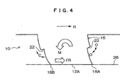
- the ground-contact length in the circumferential direction of the tire at the land portion 16 near the ground-contact end 18 becomes short, and the rigidity of the land portion is reduced.
- the groove wall 20 is not provided with the step portion 22, the land portion 16 is deformed by a moment M caused by the force FR from the road surface 26, the tread-in end 16A lifts from the road surface 26 in the direction of arrow U, and the tread-in end 16A can not bear the ground-contact pressure.
- the average groove width WA of the step portion 22 at the side of the tread side 12A is widened toward the axial outer side of the tire
- the width WS of the step portion 22 is increased toward the axial outer side of the tire
- the groove wall 20 of the lug groove 14 is provided with the step portion 22, in the portion of the land portion 16 close to the ground-contact end 18 where the ground-contact length is short, the rigidity of the skirt of the land portion 16 is enhanced and deformation of the land portion 16 can be suppressed.
- the deformation of the land portion 16 can be absorbed by the step portion 22, the lift of the land portion 16 from the road surface 26 at the tread-in end 16A can be suppressed, and the tread-in end 16A can bear the ground-contact pressure and the abrasion of the kicking end 18 can be reduced.
- the deformation at the tread-in side is generated in a direction (direction of the arrow O) in which the angle ⁇ of the step portion 22 is increased
- the deformation at the kicking-side is generated in a direction (direction of arrow C) in which the angle ⁇ of the step portion 22 is reduced, thereby absorbing the deformation of the land portion 16 caused by the moment M.
- a distance from the tread side 12A to the step portion 22 is appropriately set and the angle ⁇ formed between the step portion 22 and the tread side groove wall 20A is also appropriately set. Therefore, the effect of the step portion 22 can be exhibited most effectively.
- the volume of the lug groove 14 is sufficiently secured (volume of the tread rubber is not excessive) even in a portion of the land portion 16 where the ground-contact length close to the tire equatorial plane CL is long, and radiation ability and drainage ability are maintained.
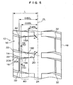
- a pneumatic tire 30 of the present embodiment in the pneumatic tire 10 of the first embodiment, a circumferential groove 32 extending in the circumferential direction of the tire is formed in the tread 12 in a region where a distance from the tire equatorial plane CL toward the axial outer side of the tire is in a range of from 0.55L to 0.70L.
- the reason why the position where the circumferential groove 32 is formed is set in this manner is that if the distance is less than 0.55L, the rigidity near the circumferential groove 32 is lowered and the biased abrasion resistance is deteriorated, and if the distance exceeds 0.70L, the effect of the circumferential groove 32 is not easily transmitted to the 1/4 point, the influence of the lug groove angle near the ground-contact end 18 exerted on the biased abrasion suppressing effect can not be eliminated.
- the groove width of the circumferential groove 32 is in a range of from 0.01L to 0.1L with respect to a distance L from the tire equatorial plane CL to the ground-contact end 18, and a groove depth of the circumferential groove 32 is in a range of from 20 to 60% of a groove depth of the lug groove 14.
- the groove width and the groove depth of the circumferential groove 32 are appropriately set as described above, it is possible to suppress a crack, or the like, generated from the groove bottom of the circumferential groove 32.
- test conditions further include that the tire size is 40.00 R 57, internal pressure is 700 kPa, tires are mounted on front wheels which are steering wheels, running speed is 20 km/h, running speed is 30000 km, and the road surface is unpaved.
- a pneumatic tire 50 relating to the conventional examples, groove walls 54 of a lug groove 52 are inclined at a tread-in end 56A and a kicking end 56B of a land portion 56 in the same direction with respect to the axial direction of the tire.
- the reference numeral 58 represents a center rib
- the reference numeral 60 represents a tread.
- the pneumatic tire of the embodiment 1 includes the tread 12 shown in Figs. 1A and 1B , the inclination angle ⁇ of the tread side groove wall 20A is in a range of from 70° to 85°, and the groove depth of the lug groove 14 is 90 mm.
- the width WS of the step portion 22 at the ground-contact end 18 is 15 mm, and its width is reduced toward the tire equatorial plane CL.
- a groove width of the lug groove 14 near the tread side 12A of the ground-contact end 18 is 80 mm.
- the pneumatic tire of the embodiment 2 is different from the pneumatic tire of the embodiment 1 in that corners between the step portion 22 and the tread side groove wall 20A have a curvature as shown in Fig. 1C , and other structures are the same as those of the embodiment 1.
- the pneumatic tire of the embodiment 3 is different from the pneumatic tire of the embodiment in that the circumferential groove 32 is formed as shown in Fig. 5 , and other structures are the same as those of the embodiment 1.
- the comparative example 1 has excessively small inclination angle ⁇
- the comparative example 2 has excessively large inclination angle ⁇
- the comparative example 3 has the circumferential groove 32 located on excessively inner side (close to the tire equatorial plane CL)
- the comparative example 4 has the circumferential groove 32 located on excessively outer side (closet to the ground-contact end 18).
- the biased abrasion resistance is more excellent.
- the abrasion amount of rubber is converted into rubber weight, and this is indicated using index in which a value of the conventional example is 100. As the numeric value is smaller, the abrasion amount is less.
- the comparative example 5 has the step portion 22 located on the groove bottom side of the lug groove 14, and the comparative example 6 has the step portion 22 located on the side of the tread side 12A.
- the angle ⁇ formed between the tread side groove wall 20A and the step portion 22 is acute angle, and in the comparative example 8, the angle ⁇ is obtuse angle.
- the biased abrasion resistance is more excellent.
- the abrasion amount of the rubber is converted into rubber weight, and this is indicated using index in which a value of the conventional example is 100 as in the above test example. As the numeric value is smaller, the abrasion amount is less.
- a length of a crack generated in the step portion 22 is also indicated as an index of wrench performance of the land portion.
Landscapes
- Engineering & Computer Science (AREA)
- Mechanical Engineering (AREA)
- Tires In General (AREA)
Claims (4)
- Pneumatique (10) ayant des rainures en barrette (14) agencées dans une bande de roulement (12) dans une direction croisant une direction circonférentielle du pneumatique et agencées dans la direction circonférentielle du pneumatique, et des parties de méplats (16) divisées par les rainures en barrette, dans lequel
lorsqu'une distance d'une extrémité de contact avec le sol (18) jusqu'à un plan équatorial du pneumatique est définie par L dans un état dans lequel le pneumatique est monté sur une jante normale et qu'une pression interne normale est chargée dans le pneumatique et qu'une charge normale est appliquée au pneumatique, dans une région où une distance du plan équatorial du pneumatique (CL) jusqu'à un côté externe axial du pneumatique se trouve dans la plage de 0,45 L à 0,55 L,
une partie étagée (22) qui est une frontière entre une paroi de rainure côté bande de roulement (20A) et une paroi de rainure côté centre du pneumatique (20B) est respectivement prévue sur les deux côtés de la rainure en barrette, et
les parois de rainures côté bande de roulement au niveau d'une extrémité d'attaque (16A) de la bande de roulement et d'une extrémité de queue (16B) de la bande de roulement de la partie de méplat sont inclinées dans des directions opposées entre elles par rapport à une direction axiale du pneumatique,
caractérisé en ce qu'une largeur de rainure moyenne (WA) côté bande de roulement des parties étagées s'élargit vers le côté externe axial du pneumatique et la largeur de la partie étagée (WS) s'accroît vers le côté externe axial du pneumatique. - Pneumatique de la revendication 1, dans lequel une rainure circonférentielle (32) s'étendant dans la direction circonférentielle du pneumatique est formée au niveau d'une région de la bande de roulement où une distance du plan équatorial du pneumatique jusqu'au côté externe axial du pneumatique se trouve dans la plage de 0,55 L à 0,70 L.
- Pneumatique de la revendication 1 ou 2, dans lequel une position de profondeur où la partie étagée est formée est une position allant de 0,3 à 0,7 fois d'une profondeur de rainure de la rainure en barrette du côté bande de roulement jusqu'au côté centre du pneumatique.
- Pneumatique selon l'une quelconque des revendications 1 à 3, dans lequel un angle formé entre la partie étagée et la paroi de rainure côté bande de roulement reliée à la partie étagée se trouve dans la plage de 70° à 120°.
Applications Claiming Priority (2)
| Application Number | Priority Date | Filing Date | Title |
|---|---|---|---|
| JP2005027757A JP4602782B2 (ja) | 2005-02-03 | 2005-02-03 | 重荷重用空気入りタイヤ |
| PCT/JP2006/300162 WO2006082696A1 (fr) | 2005-02-03 | 2006-01-11 | Pneumatique |
Publications (3)
| Publication Number | Publication Date |
|---|---|
| EP1867496A1 EP1867496A1 (fr) | 2007-12-19 |
| EP1867496A4 EP1867496A4 (fr) | 2009-08-05 |
| EP1867496B1 true EP1867496B1 (fr) | 2010-08-18 |
Family
ID=36777085
Family Applications (1)
| Application Number | Title | Priority Date | Filing Date |
|---|---|---|---|
| EP06711511A Expired - Lifetime EP1867496B1 (fr) | 2005-02-03 | 2006-01-11 | Pneumatique |
Country Status (6)
| Country | Link |
|---|---|
| US (1) | US8800618B2 (fr) |
| EP (1) | EP1867496B1 (fr) |
| JP (1) | JP4602782B2 (fr) |
| CN (1) | CN101111398B (fr) |
| ES (1) | ES2350850T3 (fr) |
| WO (1) | WO2006082696A1 (fr) |
Families Citing this family (18)
| Publication number | Priority date | Publication date | Assignee | Title |
|---|---|---|---|---|
| JP4690064B2 (ja) * | 2005-02-03 | 2011-06-01 | 株式会社ブリヂストン | 空気入りタイヤ |
| JP4137900B2 (ja) * | 2005-02-22 | 2008-08-20 | 住友ゴム工業株式会社 | 農用車輪 |
| JP4968895B2 (ja) | 2006-09-25 | 2012-07-04 | 東洋ゴム工業株式会社 | 悪路走行用空気入りタイヤ |
| CN101497298B (zh) * | 2008-01-30 | 2011-01-05 | 山东玲珑橡胶有限公司 | 一种阶梯式花纹沟曲纹载重斜交轮胎 |
| JP5435877B2 (ja) * | 2008-01-31 | 2014-03-05 | 株式会社ブリヂストン | 空気入りタイヤ |
| JP5265212B2 (ja) * | 2008-02-12 | 2013-08-14 | 株式会社ブリヂストン | 重荷重用空気入りラジアルタイヤ |
| JP4510903B2 (ja) * | 2008-03-24 | 2010-07-28 | 住友ゴム工業株式会社 | 空気入りタイヤ |
| WO2013088726A1 (fr) * | 2011-12-13 | 2013-06-20 | 株式会社ブリヂストン | Pneumatique |
| JP5887159B2 (ja) * | 2012-02-08 | 2016-03-16 | 株式会社ブリヂストン | 建設車両用タイヤ |
| JP5799043B2 (ja) * | 2013-03-13 | 2015-10-21 | 株式会社ブリヂストン | 空気入りタイヤ |
| USD746220S1 (en) | 2014-04-13 | 2015-12-29 | Bridgestone Americas Tire Operations, Llc | Tire tread |
| CN105172480B (zh) * | 2014-05-26 | 2018-09-04 | 住友橡胶工业株式会社 | 充气轮胎 |
| WO2017187960A1 (fr) * | 2016-04-28 | 2017-11-02 | 株式会社ブリヂストン | Pneumatique |
| JP6841079B2 (ja) * | 2017-02-22 | 2021-03-10 | 横浜ゴム株式会社 | 空気入りタイヤ |
| FR3068648A1 (fr) * | 2017-07-04 | 2019-01-11 | Compagnie Generale Des Etablissements Michelin | Bande de roulement de pneumatique pour vehicule agricole |
| USD858427S1 (en) | 2017-11-02 | 2019-09-03 | Cooper Tire & Rubber Company | Tire tread |
| USD858428S1 (en) | 2017-11-02 | 2019-09-03 | Cooper Tire & Rubber Company | Tire tread |
| CN115891512B (zh) * | 2022-11-29 | 2024-09-03 | 江苏通用科技股份有限公司 | 全钢子午线矿山轮胎花纹散热结构 |
Family Cites Families (14)
| Publication number | Priority date | Publication date | Assignee | Title |
|---|---|---|---|---|
| JPS5369304A (en) * | 1976-12-03 | 1978-06-20 | Bridgestone Corp | Low-noise pneumatic tire |
| JPS585803B2 (ja) * | 1979-01-13 | 1983-02-01 | 株式会社ブリヂストン | 低騒音ラグタイヤ |
| JPH0659765B2 (ja) * | 1984-09-03 | 1994-08-10 | 住友ゴム工業株式会社 | 重車両用タイヤ |
| JPH0521441Y2 (fr) * | 1986-03-18 | 1993-06-02 | ||
| JP2918227B2 (ja) * | 1988-02-29 | 1999-07-12 | オーツタイヤ株式会社 | 空気入りタイヤのトレッド部の構造 |
| JPH02179507A (ja) * | 1988-12-29 | 1990-07-12 | Bridgestone Corp | 空気入りタイヤ |
| JPH05607A (ja) * | 1991-06-25 | 1993-01-08 | Sumitomo Rubber Ind Ltd | 空気入りタイヤ |
| JPH05229312A (ja) * | 1992-02-20 | 1993-09-07 | Bridgestone Corp | 空気入りラグタイヤ |
| CA2257612A1 (fr) * | 1996-06-07 | 1997-12-11 | The Goodyear Tire & Rubber Company | Bande de roulement convertible pour pneu radial de camion ou de remorque |
| JP4227239B2 (ja) | 1999-03-18 | 2009-02-18 | 株式会社ブリヂストン | 空気入りタイヤ |
| JP2001039124A (ja) | 1999-07-28 | 2001-02-13 | Bridgestone Corp | 空気入りタイヤ |
| JP2002067625A (ja) * | 2000-09-04 | 2002-03-08 | Bridgestone Corp | 空気入りタイヤ及びその製造方法 |
| EP1566291B1 (fr) * | 2002-11-06 | 2011-07-20 | Bridgestone Corporation | Pneumatique |
| JP4521829B2 (ja) * | 2005-11-09 | 2010-08-11 | 東洋ゴム工業株式会社 | 空気入りタイヤ |
-
2005
- 2005-02-03 JP JP2005027757A patent/JP4602782B2/ja not_active Expired - Fee Related
-
2006
- 2006-01-11 CN CN2006800037495A patent/CN101111398B/zh not_active Expired - Fee Related
- 2006-01-11 WO PCT/JP2006/300162 patent/WO2006082696A1/fr not_active Ceased
- 2006-01-11 US US11/883,550 patent/US8800618B2/en active Active
- 2006-01-11 ES ES06711511T patent/ES2350850T3/es not_active Expired - Lifetime
- 2006-01-11 EP EP06711511A patent/EP1867496B1/fr not_active Expired - Lifetime
Also Published As
| Publication number | Publication date |
|---|---|
| ES2350850T3 (es) | 2011-01-27 |
| EP1867496A1 (fr) | 2007-12-19 |
| US8800618B2 (en) | 2014-08-12 |
| CN101111398B (zh) | 2010-05-19 |
| JP2006213175A (ja) | 2006-08-17 |
| WO2006082696A1 (fr) | 2006-08-10 |
| JP4602782B2 (ja) | 2010-12-22 |
| US20080041509A1 (en) | 2008-02-21 |
| CN101111398A (zh) | 2008-01-23 |
| EP1867496A4 (fr) | 2009-08-05 |
Similar Documents
| Publication | Publication Date | Title |
|---|---|---|
| EP1867496B1 (fr) | Pneumatique | |
| EP3296127B1 (fr) | Pneumatique | |
| EP3647077B1 (fr) | Pneumatique | |
| EP3056359B1 (fr) | Pneumatique | |
| EP3205516B1 (fr) | Pneumatique | |
| EP3118025B1 (fr) | Pneumatique | |
| EP3135504B1 (fr) | Pneu pour poids lourds | |
| EP2210749B1 (fr) | Pneumatique | |
| EP3572243B1 (fr) | Pneumatique | |
| EP3398793B1 (fr) | Pneumatique | |
| EP3299183B1 (fr) | Pneumatique | |
| EP2127907B1 (fr) | Pneu | |
| EP2692543B1 (fr) | Pneumatique | |
| EP3466726B1 (fr) | Pneumatique | |
| EP2610083B1 (fr) | Pneu | |
| CN103182904A (zh) | 充气轮胎 | |
| EP2298578B1 (fr) | Bandage pneumatique | |
| EP3321103B1 (fr) | Pneu pour poids lourd | |
| EP3375636B1 (fr) | Pneumatique | |
| EP4173846B1 (fr) | Pneumatique | |
| EP3960504B1 (fr) | Pneumatique | |
| EP3575110A1 (fr) | Pneumatique | |
| EP3822093B1 (fr) | Pneumatique | |
| EP1571010B1 (fr) | Pneu | |
| EP3025878B1 (fr) | Pneu pour poids lourd |
Legal Events
| Date | Code | Title | Description |
|---|---|---|---|
| PUAI | Public reference made under article 153(3) epc to a published international application that has entered the european phase |
Free format text: ORIGINAL CODE: 0009012 |
|
| 17P | Request for examination filed |
Effective date: 20070806 |
|
| AK | Designated contracting states |
Kind code of ref document: A1 Designated state(s): ES FR LU |
|
| DAX | Request for extension of the european patent (deleted) | ||
| RBV | Designated contracting states (corrected) |
Designated state(s): ES FR LU |
|
| A4 | Supplementary search report drawn up and despatched |
Effective date: 20090706 |
|
| 17Q | First examination report despatched |
Effective date: 20091005 |
|
| GRAP | Despatch of communication of intention to grant a patent |
Free format text: ORIGINAL CODE: EPIDOSNIGR1 |
|
| RIN1 | Information on inventor provided before grant (corrected) |
Inventor name: SHIMIZU, AKIYOSHIC/O BRIDGESTONE CORPORATION |
|
| GRAS | Grant fee paid |
Free format text: ORIGINAL CODE: EPIDOSNIGR3 |
|
| GRAA | (expected) grant |
Free format text: ORIGINAL CODE: 0009210 |
|
| AK | Designated contracting states |
Kind code of ref document: B1 Designated state(s): ES FR LU |
|
| REG | Reference to a national code |
Ref country code: ES Ref legal event code: FG2A Effective date: 20110117 |
|
| PLBE | No opposition filed within time limit |
Free format text: ORIGINAL CODE: 0009261 |
|
| STAA | Information on the status of an ep patent application or granted ep patent |
Free format text: STATUS: NO OPPOSITION FILED WITHIN TIME LIMIT |
|
| 26N | No opposition filed |
Effective date: 20110519 |
|
| REG | Reference to a national code |
Ref country code: FR Ref legal event code: CA Effective date: 20140812 |
|
| REG | Reference to a national code |
Ref country code: FR Ref legal event code: PLFP Year of fee payment: 11 |
|
| REG | Reference to a national code |
Ref country code: FR Ref legal event code: PLFP Year of fee payment: 12 |
|
| REG | Reference to a national code |
Ref country code: FR Ref legal event code: PLFP Year of fee payment: 13 |
|
| PGFP | Annual fee paid to national office [announced via postgrant information from national office to epo] |
Ref country code: LU Payment date: 20230123 Year of fee payment: 18 Ref country code: FR Payment date: 20230124 Year of fee payment: 18 Ref country code: ES Payment date: 20230330 Year of fee payment: 18 |
|
| P01 | Opt-out of the competence of the unified patent court (upc) registered |
Effective date: 20230531 |
|
| PG25 | Lapsed in a contracting state [announced via postgrant information from national office to epo] |
Ref country code: LU Free format text: LAPSE BECAUSE OF NON-PAYMENT OF DUE FEES Effective date: 20240111 |
|
| PG25 | Lapsed in a contracting state [announced via postgrant information from national office to epo] |
Ref country code: LU Free format text: LAPSE BECAUSE OF NON-PAYMENT OF DUE FEES Effective date: 20240111 |
|
| PG25 | Lapsed in a contracting state [announced via postgrant information from national office to epo] |
Ref country code: FR Free format text: LAPSE BECAUSE OF NON-PAYMENT OF DUE FEES Effective date: 20240131 |
|
| PG25 | Lapsed in a contracting state [announced via postgrant information from national office to epo] |
Ref country code: FR Free format text: LAPSE BECAUSE OF NON-PAYMENT OF DUE FEES Effective date: 20240131 |
|
| REG | Reference to a national code |
Ref country code: ES Ref legal event code: FD2A Effective date: 20250227 |
|
| PG25 | Lapsed in a contracting state [announced via postgrant information from national office to epo] |
Ref country code: ES Free format text: LAPSE BECAUSE OF NON-PAYMENT OF DUE FEES Effective date: 20240112 |