EP1867599A2 - Pédale de commande pour véhicule industriel et véhicule industriel doté de celle-ci - Google Patents
Pédale de commande pour véhicule industriel et véhicule industriel doté de celle-ci Download PDFInfo
- Publication number
- EP1867599A2 EP1867599A2 EP07110211A EP07110211A EP1867599A2 EP 1867599 A2 EP1867599 A2 EP 1867599A2 EP 07110211 A EP07110211 A EP 07110211A EP 07110211 A EP07110211 A EP 07110211A EP 1867599 A2 EP1867599 A2 EP 1867599A2
- Authority
- EP
- European Patent Office
- Prior art keywords
- pedal
- operator
- pedal portion
- step surface
- industrial vehicle
- Prior art date
- Legal status (The legal status is an assumption and is not a legal conclusion. Google has not performed a legal analysis and makes no representation as to the accuracy of the status listed.)
- Withdrawn
Links
- 230000000994 depressogenic effect Effects 0.000 claims abstract description 19
- 210000003127 knee Anatomy 0.000 description 5
- 230000007246 mechanism Effects 0.000 description 4
- 230000004075 alteration Effects 0.000 description 3
- 238000010276 construction Methods 0.000 description 2
- 230000000881 depressing effect Effects 0.000 description 2
- 230000000903 blocking effect Effects 0.000 description 1
- 230000008859 change Effects 0.000 description 1
- 230000000694 effects Effects 0.000 description 1
- 230000006872 improvement Effects 0.000 description 1
Images





Classifications
-
- G—PHYSICS
- G05—CONTROLLING; REGULATING
- G05G—CONTROL DEVICES OR SYSTEMS INSOFAR AS CHARACTERISED BY MECHANICAL FEATURES ONLY
- G05G1/00—Controlling members, e.g. knobs or handles; Assemblies or arrangements thereof; Indicating position of controlling members
- G05G1/30—Controlling members actuated by foot
- G05G1/50—Manufacturing of pedals; Pedals characterised by the material used
- G05G1/506—Controlling members for foot-actuation
-
- B—PERFORMING OPERATIONS; TRANSPORTING
- B66—HOISTING; LIFTING; HAULING
- B66F—HOISTING, LIFTING, HAULING OR PUSHING, NOT OTHERWISE PROVIDED FOR, e.g. DEVICES WHICH APPLY A LIFTING OR PUSHING FORCE DIRECTLY TO THE SURFACE OF A LOAD
- B66F9/00—Devices for lifting or lowering bulky or heavy goods for loading or unloading purposes
- B66F9/06—Devices for lifting or lowering bulky or heavy goods for loading or unloading purposes movable, with their loads, on wheels or the like, e.g. fork-lift trucks
- B66F9/075—Constructional features or details
- B66F9/07504—Accessories, e.g. for towing, charging, locking
-
- B—PERFORMING OPERATIONS; TRANSPORTING
- B66—HOISTING; LIFTING; HAULING
- B66F—HOISTING, LIFTING, HAULING OR PUSHING, NOT OTHERWISE PROVIDED FOR, e.g. DEVICES WHICH APPLY A LIFTING OR PUSHING FORCE DIRECTLY TO THE SURFACE OF A LOAD
- B66F9/00—Devices for lifting or lowering bulky or heavy goods for loading or unloading purposes
- B66F9/06—Devices for lifting or lowering bulky or heavy goods for loading or unloading purposes movable, with their loads, on wheels or the like, e.g. fork-lift trucks
- B66F9/075—Constructional features or details
- B66F9/0759—Details of operating station, e.g. seats, levers, operator platforms, cabin suspension
-
- Y—GENERAL TAGGING OF NEW TECHNOLOGICAL DEVELOPMENTS; GENERAL TAGGING OF CROSS-SECTIONAL TECHNOLOGIES SPANNING OVER SEVERAL SECTIONS OF THE IPC; TECHNICAL SUBJECTS COVERED BY FORMER USPC CROSS-REFERENCE ART COLLECTIONS [XRACs] AND DIGESTS
- Y10—TECHNICAL SUBJECTS COVERED BY FORMER USPC
- Y10T—TECHNICAL SUBJECTS COVERED BY FORMER US CLASSIFICATION
- Y10T74/00—Machine element or mechanism
- Y10T74/20—Control lever and linkage systems
- Y10T74/20528—Foot operated
-
- Y—GENERAL TAGGING OF NEW TECHNOLOGICAL DEVELOPMENTS; GENERAL TAGGING OF CROSS-SECTIONAL TECHNOLOGIES SPANNING OVER SEVERAL SECTIONS OF THE IPC; TECHNICAL SUBJECTS COVERED BY FORMER USPC CROSS-REFERENCE ART COLLECTIONS [XRACs] AND DIGESTS
- Y10—TECHNICAL SUBJECTS COVERED BY FORMER USPC
- Y10T—TECHNICAL SUBJECTS COVERED BY FORMER US CLASSIFICATION
- Y10T74/00—Machine element or mechanism
- Y10T74/20—Control lever and linkage systems
- Y10T74/20576—Elements
- Y10T74/20888—Pedals
- Y10T74/209—Extension
- Y10T74/20906—Offset
Definitions
- the present invention relates to an accelerator pedal and an industrial vehicle having the same.
- Japanese Unexamined Patent Application Publications Nos. 2001-248461 , 2005-335854 and 2000-318498 disclose a seat swiveling device which can change the direction of a seat.
- a forklift truck having any one of the seat swiveling devices disclosed in the Japanese Unexamined Patent Application Publications can decrease the extent of body twisting of the operator thereby to reduce the fatigue.
- the Japanese Unexamined Patent Application Publication No. 2001-248461 discloses an industrial vehicle having a main accelerator pedal which is interlocked with an auxiliary accelerator pedal in conjunction with the operation of a seat swiveling device.
- the industrial vehicle of the above Publication requires the additional auxiliary accelerator pedal and the interlock mechanism for the additional accelerator pedal, so that the number of parts for the vehicle is increased and additional assembling needs be performed, with the result that the cost of the industrial vehicle is increased.
- the Japanese Unexamined Patent Application Publications Nos. 2005-335854 and 2000-318498 disclose a seat assembly for an industrial vehicle such as a forklift truck, having a seat swiveling shaft which is provided at a position adjacent to the front of the seat.
- the industrial vehicles of the above two Publications are advantageous over the counterpart of the first-mentioned Publication in that the right foot of the operator will not be moved away from the accelerator pedal and an additional part such as an auxiliary pedal is not necessary.
- the seat swiveling device permits changing of the facing direction of the operator's body from the forward-facing position slightly toward the right, it is difficult for the operator to push the accelerator pedal properly because the position of the accelerator pedal is fixed. Thus, operability of the accelerator pedal for use with the seat swiveling device needs to be improved.
- An object of the present invention is to provide an accelerator pedal and an industrial vehicle having the same that require no complicated configuration, avoid increasing the number of parts and improve the pedal operability
- an industrial vehicle includes an operating pedal depressed by an operator for operating running of the industrial vehicle.
- the operating pedal includes a first pedal portion having a first step surface which is depressed by the operator while the operator maintains his or her posture to look forward and a second pedal portion having a second step surface which is depressed by the operator while the operator maintains his or her posture to look backward.
- the second pedal portion is formed on a lateral side of the first pedal portion so as to be inclines with respect to such that an angle made between the first step surface and the second step surface is an obtuse angle.
- FIGS. 1 through 5 The following will describe a forklift truck as an industrial vehicle according to a preferred embodiment of the present invention with reference to FIGS. 1 through 5.
- the references to directions or locations such as front, rear, left, right, up and down as viewed from the forklift truck operator OP seated on a swivel seat 17 and facing forward (or forward direction) are used.
- the forklift truck has a pair of front wheels 11 and a pair of steerable rear wheels 12.
- An engine (not shown) is mounted in the center of a forklift truck body 10 and an engine hood 13 is mounted to cover the upper part of the engine.
- the front wheels 11 are driven by the engine for moving the forklift truck in forward or backward direction.
- the forklift truck further has a loading apparatus 14 which includes a working implement or a pair of forks 15 (only one fork being shown in the drawing) which is inserted into a pallet 16 in contact with its inner surface 16a and lifts a load W which is placed on the pallet 16.
- FIG. 1 shows a state in which two loads W are placed on the pallet 16, thereby blocking the forward view of the operator OP
- the swivel seat 17 as an operator's seat including a swiveling device 17a is provided on the top of the engine hood 13. As shown in FIG. 2, the swivel seat 17 is rotatable by the swiveling device 17a in clockwise direction as seen from the top for a predetermined swivel angle a from the position where the swivel seat 17 faces straight forward.
- the swivel angle a is about 20 degrees in this preferred embodiment.
- the pivot axis of the swivel seat 17 is located substantially at the center of the front end of the seat indicated by L1 in FIG 2.
- An accelerator pedal 20 as an operating pedal is disposed on a floor 19 of the forklift truck body 10 which is located under the feet of the operator OP seated on the swivel seat 17.
- An instrument panel 21 is provided in the front of the swivel seat 17 and a steering wheel 22 is mounted above the center of the instrument panel 21.
- a lift lever 23 and a tilt lever 24 are mounted on the right side of the steering wheel 22 for lifting and tilting operation.
- a brake pedal 25 and a clutch pedal 26 are disposed below and rearward of the instrument panel 21,
- An overhead guard 27 is arranged above the swivel seat 17 so as to cover the operator OP.
- the accelerator pedal 20 includes a main pedal portion 20a as a first pedal portion and a sub-pedal portion 20b as a second pedal portion.
- the shape of the surface of the main pedal portion 20a is a parallelogram whose vertical lateral sides are longer than the horizontal top and bottom sides and the thickness of the main pedal portion 20a is a few centimeters.
- the main pedal portion 20a has a step surface 20c as a first step surface which faces the operator OP seated on the swivel seat 17 and is depressed by the operator OP in driving the forklift truck.
- Plural antislip grooves 20e are formed vertically in the step surface 20c of the main pedal portion 20a.
- the shape of the surface of the sub-pedal portion 20b is a parallelogram and has substantially the same thickness as the main pedal portion 20a;
- the longitudinal length of the sub-pedal portion 20b as measured in vertical direction is about one-third of the main pedal portion 20a and width of the sub-pedal portion 20b is substantially the same as that of the main pedal portion 20a.
- the face of the sub-pedal portion 20b which faces the back of the forklift is a step surface 20d as a second step surface pushed by the operator OP in driving operation.
- the face of the sub-pedal portion 20b in this preferred embodiment faces the front of the operator OP when he or she is seated on the swivel seat 17.
- Plural antislip grooves 20f are formed in the step surface 20d of the sub-pedal portion 20b in the longitudinal direction thereof.
- the sub-pedal portion 20b is formed integral with the main pedal portion 20a on the right side thereof in parallel relation thereto. That is, the second pedal portion is located on the side to which the operator seat is rotated.
- the sub-pedal portion 20b extends rightward from the main pedal portion 20a at an inclination angle ⁇ that is made between the face of the sub-pedal portion 20b which faces the front of the forklift truck and an imaginary plane extending from the face of the main pedal portion 20a which faces the front of the forklift truck.
- this inclination angle ⁇ is about 20 degrees.
- the sub-pedal portion 20b is formed integrally with the main pedal portion 20a so as to be inclined with respect to such that the angle made between the step surface 20c of the main pedal portion 20a and the step surface 20d of the sub-pedal portion 20b is an obtuse angle.
- the obtuse angle and the inclination angle ß make 180 degrees. It is preferable that the inclination angle ß should be substantially same as the swivel angle a so that the step surface 20d of the sub-pedal portion 20b faces toward the operator OP when the swivel seat 17 on which the operator OP is seated is turned for the angle ß.
- Link mechanism which is connected to a throttle valve (not shown) is provided in the face of the main pedal portion 20a which faces the front of the forklift truck.
- Reference symbol R in FIG. 3A designates an axis which is located adjacent to and parallel to the bottom end of the main pedal portion 20a and about which the accelerator pedal 20 is pivoted when its main pedal portion 20a or sub-pedal portion 20b is depressed by the operator OP.
- the operator OP takes a posture to look behind the forklift truck.
- the operator OP turns the swivel seat 17 clockwise as seen from the top for the angle a around the pivot axis L1, then the operator OP twists his or her upper part of the body to the right to look backward.
- the right knee of the operator OP is opened or moved rightward and the right foot of the operator OP is moved away from the main pedal portion 20a, as shown in FIG. 5B.
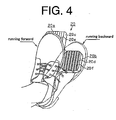
- the right foot is turned rightward about his or her heel, as shown by dotted-line foot in FIG. 4.
- the toe of the right foot of the operator OP is placed on the step surface 20d of the sub-pedal portion 20b of the accelerator pedal 20.
- the operator OP twists his or her upper part of the body rightwardly backward and depresses the sub-pedal portion 20b while maintaining the posture to look backward.
- Depressing the sub-pedal portion 20b, the main pedal portion 20a, with which the sub-pedal portion 20b is made integral, is pivoted in the direction R1.
- the throttle valve (not shown) is opened and the engine speed is increased. Then, the driving force of the engine is transmitted to the front wheels 11 and, therefore, the forklift truck is driven backward.
- the accelerator pedal 20 of the present embodiment of the invention functions effectively to improve the operability of a forklift truck, as will be described below.
- the right heel of the operator OP is moved rightward by a distance corresponding to the width of one foot from the main pedal portion 20a ta a position below the sub-pedal portion 20b.
- the heel of the operator OP is positioned below the sub-pedal portion 20b and the toe of the right foot of the operator OP is set on the step surface 20d of the sub-pedal portion 20b.
- the accelerator pedal 20 can be depressed by pushing the sub-pedal portion 20b with the right foot.
- the right heel may be positioned either at the main pedal portion 20a or a position below the sub-pedal portion 20b.
- the accelerator pedal 20 can be operated by the operator OP with his or her toe which is then placed on the sub-pedal portion 20b.
- the accelerator pedal 20 is also applicable to an industrial vehicle in which its seat is fixed.
- the operator OP twists the upper part of his or her body rightwardly backward to look behind and the right foot of the operator OP is placed at a position such that his or her toe is turned toward the right or moves away from the accelerator pedal 20.
- the operator OP can easily operate the accelerator pedal 20 by the depressing the sub-pedal portion 20b which is provided adjacent to the operator OP and, therefore, the pedal operability is improved.
- the size of the sub-pedal portion 20b may be changed. If the seat is made with a larger swivel angle a, the position of the right foot of the operator OP moves further away from the accelerator pedal 20. Then, the size of the sub-pedal portion 20b may be changed such that it is extended laterally In view of a case that the heel of the right foot of the operator OP who is looking backward is located below the sub-pedal portion 20b, the sub-pedal portion 20b may be made so as to have the same length as the main pedal portion 20a. In either case, operability of the accelerator pedal 20 can be improved.
- the inclination angle ⁇ of the sub-pedal portion 20b may be between 0 degree and under 90 degrees. That is, the inclination angle ⁇ of the sub-pedal portion 20b with respect to the main pedal portion 20a may be changed so as to suit specific accelerator pedal used in each different model of industrial vehicle such as forklift truck.
- the inclination angle ⁇ may be selected from the above range according to the physique size and personal preference of the operator.
- the sub-pedal portion 20b may be formed as shown in FIG 6, wherein the sub-pedal portion 20b is tilted backward about its bottom side so that the plane of the step surface 20d extends substantially perpendicularly to the floor of the forklift truck.
- the sub-pedal portion 20b is closer to the operator OP and, therefore, pedal operability can be improved.
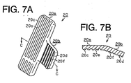
- Part of the accelerator pedal 20 between the step surface 20c of the main pedal portion 20a and the step surface 20d of the sub-pedal portion 20b may be formed with a curvature, as shown in FIG. 7, which can be improve operability of the accelerator pedal 20 when the operator OP depresses the accelerator pedal 20 at the area thereof between the step surface 20d of the main pedal portion 20a and the step surface 20d of the sub-pedal portion 20b.
- the accelerator pedal 20 may be constructed such that the sub-pedal portion 20b is detachably mounted to the main pedal portion 20a, An increase of the number of parts for such accelerator pedal is restricted as compared with the above-cited conventional art and good pedal operability is maintained. Additionally, the detachable sub-pedal portion 20b is advantageously applicable to an existing forklift truck without removing its existing accelerator pedal.
- the pivot axis L1 of the swivel seat 17 may be located further forward of the center of the front end of the swivel seat 17 (refer to FIG. 8).
- the swivel seat 17 may be constructed so that it is rotatable in counter-clockwise direction as viewed from the top.
- the sub-pedal portion 20b is located on the left side of the main pedal portion 20a and the operator twists the upper part of the body toward the left in looking backward while driving the forklift truck.
- the operator OP can operate the sub-pedal portion 20b on the left side of the main pedal portion 20a when he or she looks backward and his or her foot is shifted leftward.
- the present invention is further applicable to industrial vehicle other than the forklift truck, such as shovel loader, wheel loader and skid steer loader.
- An industrial vehicle includes an operating pedal depressed by an operator for operating running of the industrial vehicle.
- the operating pedal includes a first pedal portion having a first step surface which is depressed by the operator while the operator maintains his or her posture to look forward and a second pedal portion having a second step surface which is depressed by the operator while the operator maintains his or her posture to look backward.
- the second pedal portion is formed on a lateral side of the first pedal portion so as to be inclines with respect to such that an angle made between the first step surface and the second step surface is an obtuse angle
Landscapes
- Engineering & Computer Science (AREA)
- Transportation (AREA)
- Structural Engineering (AREA)
- Geology (AREA)
- Civil Engineering (AREA)
- Life Sciences & Earth Sciences (AREA)
- Mechanical Engineering (AREA)
- Automation & Control Theory (AREA)
- General Physics & Mathematics (AREA)
- Physics & Mathematics (AREA)
- Manufacturing & Machinery (AREA)
- Auxiliary Drives, Propulsion Controls, And Safety Devices (AREA)
- Mechanical Control Devices (AREA)
- Forklifts And Lifting Vehicles (AREA)
- Control Of Throttle Valves Provided In The Intake System Or In The Exhaust System (AREA)
Applications Claiming Priority (1)
| Application Number | Priority Date | Filing Date | Title |
|---|---|---|---|
| JP2006166321A JP2007331593A (ja) | 2006-06-15 | 2006-06-15 | 走行操作ペダル及び走行操作ペダルを備えた産業車両 |
Publications (1)
| Publication Number | Publication Date |
|---|---|
| EP1867599A2 true EP1867599A2 (fr) | 2007-12-19 |
Family
ID=38523490
Family Applications (1)
| Application Number | Title | Priority Date | Filing Date |
|---|---|---|---|
| EP07110211A Withdrawn EP1867599A2 (fr) | 2006-06-15 | 2007-06-13 | Pédale de commande pour véhicule industriel et véhicule industriel doté de celle-ci |
Country Status (3)
| Country | Link |
|---|---|
| US (1) | US20070289403A1 (fr) |
| EP (1) | EP1867599A2 (fr) |
| JP (1) | JP2007331593A (fr) |
Families Citing this family (6)
| Publication number | Priority date | Publication date | Assignee | Title |
|---|---|---|---|---|
| JP4928103B2 (ja) * | 2005-09-05 | 2012-05-09 | ヤンマー株式会社 | 走行車両のペダル構造 |
| JP5113725B2 (ja) * | 2008-11-10 | 2013-01-09 | 株式会社クボタ | 作業車のペダル構造 |
| US8794102B2 (en) | 2010-05-11 | 2014-08-05 | Honda Motor Co., Ltd. | Accelerator pedal assembly for vehicle |
| JP5685470B2 (ja) * | 2011-03-31 | 2015-03-18 | 富士重工業株式会社 | 車両用操作ペダル構造 |
| JP7180248B2 (ja) * | 2018-09-28 | 2022-11-30 | マツダ株式会社 | 車両用ペダル構造 |
| JP7012966B2 (ja) * | 2019-06-14 | 2022-02-15 | イオマップ合同会社 | ブレーキペダル及び該ブレーキペダルを備えた自動車 |
Family Cites Families (7)
| Publication number | Priority date | Publication date | Assignee | Title |
|---|---|---|---|---|
| US1428843A (en) * | 1920-07-28 | 1922-09-12 | Frederick C Grant | Pedal attachment for automobiles |
| US1445355A (en) * | 1921-11-17 | 1923-02-13 | Reichert John | Pedal extension |
| US5231891A (en) * | 1989-05-16 | 1993-08-03 | Kubota Corp. | Double pedal mechanism for working vehicle |
| DE29723095U1 (de) * | 1997-06-12 | 1998-03-26 | Schatz, Werner, 72631 Aichtal | Flurförderfahrzeug |
| EP1260477A1 (fr) * | 2000-03-01 | 2002-11-27 | TCM Corporation | Vehicule industriel |
| JP2001248461A (ja) * | 2000-03-01 | 2001-09-14 | Tcm Corp | 産業用車両 |
| JP2004123334A (ja) * | 2002-10-03 | 2004-04-22 | Toyota Industries Corp | 産業車両用アクセルペダル |
-
2006
- 2006-06-15 JP JP2006166321A patent/JP2007331593A/ja active Pending
-
2007
- 2007-06-13 EP EP07110211A patent/EP1867599A2/fr not_active Withdrawn
- 2007-06-14 US US11/818,803 patent/US20070289403A1/en not_active Abandoned
Also Published As
| Publication number | Publication date |
|---|---|
| JP2007331593A (ja) | 2007-12-27 |
| US20070289403A1 (en) | 2007-12-20 |
Similar Documents
| Publication | Publication Date | Title |
|---|---|---|
| EP1867599A2 (fr) | Pédale de commande pour véhicule industriel et véhicule industriel doté de celle-ci | |
| EP1743864A2 (fr) | Chariot industriel | |
| EP3396073B1 (fr) | Dispositif pour le fonctionnement d'une machine de construction | |
| EP2700754A1 (fr) | Engin de chantier | |
| US5921340A (en) | Industrial truck with a swivelling driver's seat | |
| WO2018088000A1 (fr) | Véhicule de manutention de cargaison de type vertical | |
| US20130074645A1 (en) | Control lever for operating a working machine | |
| JPH10131235A (ja) | 作業車両の運転席 | |
| JP7201350B2 (ja) | 作業機械およびモータグレーダ | |
| US11787291B2 (en) | Operation device and work vehicle | |
| JP2009261285A (ja) | 乗用型作業機 | |
| US20130168116A1 (en) | Cab and motor grader | |
| JP7281869B2 (ja) | 作業車両 | |
| US11256282B2 (en) | Control lever device of industrial vehicle | |
| WO2018159210A1 (fr) | Engin de chantier | |
| JP3946945B2 (ja) | コンバインのレバー装置 | |
| JP2002196833A (ja) | 作業機の操作構造 | |
| CN121403990A (zh) | 作业车辆 | |
| JPH08337132A (ja) | 産業車両の運転室及びフロアマット | |
| JPH1160185A (ja) | フォークリフトのティルト機構 | |
| JP2002145597A (ja) | ローリフトトラック | |
| JP2020095698A (ja) | 作業車両の操作レバー及び作業車両 | |
| JP2003095589A (ja) | 荷役運搬車両 | |
| JP2020091712A (ja) | 作業車両の操作レバー及び作業車両 | |
| JP2020091713A (ja) | 作業車両の操作レバー及び作業車両 |
Legal Events
| Date | Code | Title | Description |
|---|---|---|---|
| PUAI | Public reference made under article 153(3) epc to a published international application that has entered the european phase |
Free format text: ORIGINAL CODE: 0009012 |
|
| 17P | Request for examination filed |
Effective date: 20070613 |
|
| AK | Designated contracting states |
Kind code of ref document: A2 Designated state(s): AT BE BG CH CY CZ DE DK EE ES FI FR GB GR HU IE IS IT LI LT LU LV MC MT NL PL PT RO SE SI SK TR |
|
| AX | Request for extension of the european patent |
Extension state: AL BA HR MK YU |
|
| STAA | Information on the status of an ep patent application or granted ep patent |
Free format text: STATUS: THE APPLICATION HAS BEEN WITHDRAWN |
|
| 18W | Application withdrawn |
Effective date: 20090507 |