EP1870314B1 - Unité de direction électrique pour un véhicule de manutention - Google Patents
Unité de direction électrique pour un véhicule de manutention Download PDFInfo
- Publication number
- EP1870314B1 EP1870314B1 EP07012106A EP07012106A EP1870314B1 EP 1870314 B1 EP1870314 B1 EP 1870314B1 EP 07012106 A EP07012106 A EP 07012106A EP 07012106 A EP07012106 A EP 07012106A EP 1870314 B1 EP1870314 B1 EP 1870314B1
- Authority
- EP
- European Patent Office
- Prior art keywords
- steering
- gear
- slewing ring
- steering unit
- housing
- Prior art date
- Legal status (The legal status is an assumption and is not a legal conclusion. Google has not performed a legal analysis and makes no representation as to the accuracy of the status listed.)
- Active
Links
Images


Classifications
-
- B—PERFORMING OPERATIONS; TRANSPORTING
- B62—LAND VEHICLES FOR TRAVELLING OTHERWISE THAN ON RAILS
- B62D—MOTOR VEHICLES; TRAILERS
- B62D5/00—Power-assisted or power-driven steering
- B62D5/04—Power-assisted or power-driven steering electrical, e.g. using an electric servo-motor connected to, or forming part of, the steering gear
- B62D5/0418—Electric motor acting on road wheel carriers
-
- B—PERFORMING OPERATIONS; TRANSPORTING
- B62—LAND VEHICLES FOR TRAVELLING OTHERWISE THAN ON RAILS
- B62D—MOTOR VEHICLES; TRAILERS
- B62D7/00—Steering linkage; Stub axles or their mountings
- B62D7/02—Steering linkage; Stub axles or their mountings for pivoted bogies
- B62D7/023—Steering turntables
-
- B—PERFORMING OPERATIONS; TRANSPORTING
- B66—HOISTING; LIFTING; HAULING
- B66F—HOISTING, LIFTING, HAULING OR PUSHING, NOT OTHERWISE PROVIDED FOR, e.g. DEVICES WHICH APPLY A LIFTING OR PUSHING FORCE DIRECTLY TO THE SURFACE OF A LOAD
- B66F9/00—Devices for lifting or lowering bulky or heavy goods for loading or unloading purposes
- B66F9/06—Devices for lifting or lowering bulky or heavy goods for loading or unloading purposes movable, with their loads, on wheels or the like, e.g. fork-lift trucks
- B66F9/075—Constructional features or details
- B66F9/07572—Propulsion arrangements
Definitions
- the invention relates to a steering unit, in particular for a forklift truck, comprising a steering gear designed as a planetary gear with at least one gear stage and a steering motor, wherein the steering gear can be arranged in a housing, driven with the steering motor and coupled via a wheel with an impeller, wherein between the Gear stage and the wheel carrier a slewing ring bearing with a slewing ring inner ring and a slewing ring outer ring is arranged.
- Steering units for industrial trucks usually consist of hydraulic steering gears.
- a rack which is connected to a pinion, guided longitudinally displaceable by hydraulic actuation within the steering housing.
- the pinion itself is connected via a shaft directly to a wheel carrier in connection or is rotatably connected thereto.
- the WO 2005/077695 A1 discloses a steering and wheel drive for a material handling vehicle with a traction motor, a driving gear and a steering unit of the generic type.
- a traction motor By means of the traction motor and the drive gear, an impeller is driven, while the impeller is 29enkbar by the steering motor and the steering gear about a vertical axis.
- the steering gear is designed here as a multi-stage planetary gear or as a tungsten gear and has in a first embodiment, three gear stages. Within the gear stages, the planet gears are arranged, which are each rotatably connected to a planet carrier, wherein the planet gear engages in an internal toothing of a bearing inner ring of a slewing ring bearing.
- This bearing inner ring is connected via rolling elements with a bearing outer ring, so that the bearing inner ring for pivoting the drive gear and thus the impeller can rotate relative to the bearing outer ring about a vertical axis.
- the planetary bearing is firmly connected to the stationary ring gear, so that the planetary gears are held substantially stationary.
- the steering gear is designed as a planetary gear, wherein the output generated by the steering motor driven via a rotary bearing on the drive gear, so that it is pivotable about a vertical axis.
- the present invention therefore has the object of disclosing a hydraulic power unit to dispense with an electric steering unit, which allows a steering movement with the highest accuracy and also ensures the respective position of the wheels for transmission to existing control devices.
- the slewing ring inner ring is designed as a planet carrier of the gear stage.
- a fundamentally new approach is proposed, namely the use of a gear stage, which is directly coupled to a steering motor.
- the steering motor itself may be made of an electric motor, but it is conceivable that other engine variants are used.
- a conventional rack and pinion steering is completely dispensed with and instead a gear component used to directly bring about the rotational movement of the steerable impeller.
- the slewing ring inner ring simultaneously forms the planet carrier of the transmission output stage.
- an element of the gear stage is designed as a planetary gear, wherein in particular a single or multi-stage planetary gear is used.
- a steering movement with a small deflection can be effected even at a correspondingly high speed.
- a small steering motor can be used which has great dynamics.
- the housing For receiving an electric steering motor, the housing has on the connection side of the steering motor a receptacle for a bearing, which is provided for mounting the armature of the steering motor, and a cup-shaped shell to which the housing of the steering motor can be flanged flush.
- the steering motor and the housing of the steering unit thus form the desired compact unit, which is designed to be maintenance-friendly and, moreover, largely prevents deposits of dirt.
- the housing of the steering unit is bell-shaped and is already used to hold the intended gear stage. Below the gear stage, a slewing ring is provided, which is located between the gear stage and a wheel carrier.
- the housing itself is directly on the transmission side with the slewing bearing outer ring connected, preferably screwed, while the wheel carrier connected to the slewing ring inner ring, and also preferably screwed, is.
- the slewing ring inner ring and the wheel carrier may be integrally formed.
- the male load which is to be transmitted to the wheels on the wheel, is thus taken up exclusively by the turntable bearing, which is also connected in addition to the attachment to the gear stage with the chassis of the vehicle, so that all forces, in particular the load forces occurring, for example at a Forklift, can be transmitted directly over the slewing ring bearing on the wheel and the wheels.
- the slewing ring outer ring and inner ring here forms at the same time the conclusion of the housing and that on the side of the gear stage.
- the slewing ring inner ring is supported relative to the slewing ring outer ring by a plurality of bearing elements, wherein a seal may be further arranged between the ring gear outer ring and wheel, so that the proposed gear grease can not escape from the steering housing.
- the ring gears of the planetary gear used are in this case rotatably connected to the housing and thus have the advantage that they are additionally supported by the outer housing and radial forces are introduced directly into the housing, while the output via the sun or a planet carrier directly on the Drehkranzlageännenring he follows.
- the wheel carrier itself is provided for receiving at least one preferably two wheels, which are supported by bearing elements relative to the wheel carrier, wherein the wheels are designed as non-driven, but steerable over the wheel carrier wheels.
- an embodiment is selected in which the steering motor consists of an electric motor which is arranged symmetrically to the longitudinal axis of the steering unit and uses a slewing ring, which is located between the steering motor and the wheel carrier is located, wherein the slewing ring inner ring is simultaneously formed as a planet carrier of the transmission output stage.
- the steering motor consists of an electric motor which is arranged symmetrically to the longitudinal axis of the steering unit and uses a slewing ring, which is located between the steering motor and the wheel carrier is located, wherein the slewing ring inner ring is simultaneously formed as a planet carrier of the transmission output stage.
- the axes of the planet carrier lead a gear disc, so that the gear wheel rotates with the planet carrier.
- the gear wheel itself acts directly or indirectly via another gear a rotary encoder, which detects the position of the rotary bearing inner ring by a material measure and sensor elements and thus the steering angle of the wheels. With the help of the rotary encoder can thus be transmitted to the connected electronics, which position the wheels currently occupy, so that a readjustment can take place.
- the rotary encoder thus enables precise control of the wheels and a constant control to allow any readjustments in a fully automatic operation.
- the rotational angle sensor includes a material measure and at least one sensor element, wherein the material measure usually consists of a perforated disc or a structured magneto-sensitive structure, so that either photoelectric barriers or magnetic semiconductors, for example GMR sensors can be used as sensor elements.
- the rotary encoder is flanged to the housing immediately laterally adjacent to the steering motor.
- a novel electric steering unit is thus inventively provided, which is provided in particular for industrial trucks and at least one housing with steering gear and at least one gear stage, which is driven by an electric steering motor, the output via a gear component is at least one impeller and wherein the position of the impeller is detected by a rotary encoder at any time.
- the rotary encoder is in this case coupled to the transmission output stage in such a way that each steering angle can be detected directly by the rotary encoder.
- the essential advantage of the present invention is that with the help of an electric steering motor and a gear stage, an extremely sensitive steering movement can be performed, which is independent of component tolerances of the conventional rack and pinion steering and can also be used without the use of a hydraulic unit.
- this steering unit is used in industrial trucks, such as forklifts, which already have a corresponding on-board voltage through the existing batteries and are equipped with an electric steering motor, so that in addition to the electric drive also an electric steering unit can be used.
- the essential advantage of this can be achieved, further, is that an immediate control of the respective steering angle via a rotary encoder is possible.
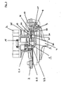
- FIG. 1 shows a steering unit 1 according to the invention, which can be used to drive a material handling vehicle, not shown.
- the steering unit 1 consists of a housing 2 and a steering motor 3 and is connected to a flanged wheel carrier 4, which is provided for receiving two wheels, not shown.
- the steering motor 3 is flanged directly to the housing 2 and connected by means not shown mounting screws with the housing 2.
- the output shaft 14 of the steering motor 3 is supported by bearing elements 15.
- the Housing 2 has for this purpose on the motor side a cup-shaped shape, on which the steering motor 3 is mounted with housing, so that a seamless transition takes place.
- a three-stage planetary gear 5 is installed in the illustrated embodiment, which is provided for transmitting the rotational movement of the steering motor 3 to a steering movement of the wheel carrier 4.
- the individual planetary stages 5.1, 5.2 and 5.3 are nested within each other within the housing 2, wherein the respective ring gears are rotatably connected to the housing 2.
- a planet carrier 6 of the third stage is in this case rotatably connected to the wheel carrier 4 and is used for the output of the steering movement.
- the wheel carrier 4 is connected to the housing 2 via a slewing ring bearing 7, which consists of a slewing bearing outer ring 8 and a slewing ring inner ring 9.
- the slewing ring outer ring 8 is in this case rotatably connected by means of bolts 10 with the housing 2 and supported by a further screw 17 to the vehicle frame 18, while the slewing ring inner ring 9 via bearing means 11 and rotatably connected on the one hand with the wheel carrier 4 and on the other hand with the planet carrier 6.
- a sealing ring 16 is provided for sealing the gear stage, so that the existing lubricant, such as gear grease within the gear stage can not escape.
- the wheel carrier 4 is provided in the proposed embodiment for receiving two wheels, which are each supported on a stub shaft.
- a wheel receptacle 12 is placed at the end, which in turn are supported by bearing means 19, 20 relative to the stub shaft and has fastening bolts 13, on which the impeller is placed and screwed.
- a wheel carrier can be provided for receiving only a single impeller.
- the peculiarity of the present invention is that instead of a conventional hydraulic steering gear such with an electric steering motor and a gear stage is used, wherein the high speed of the steering motor by, for example, a 3-stage planetary gear 5 so far reduced is that the pivot bearing inner ring 9, which is directly connected to the wheel carrier 4, performs a slow rotational movement, which is used as a steering movement for the wheels.
- the executed rotational movement is very precise and subject to small tolerances.
- a particular advantage here is to take into account that high torques can be transmitted. Furthermore, the exact position can be determined by appropriate sensors.
- FIG. 2 shows in a perspective rear view of an industrial truck 100 with a front drive shaft 101 and a rear steering unit 102, which again in a single representation of the FIG. 2 is shown.
- the industrial truck 100 has a box-shaped structure 103 with a driver's seat 104 and a steering 105, which acts directly on the steering unit 102.
- an open canopy 106 is arranged to protect the driver from falling objects.
- the industrial vehicle 100 has two forks 107 for lifting loads, which are arranged movable in a guide 108 upwards.
- the front axle 101 has two single wheels 109, each having an unrecognizable drive motor.
- the rear steering unit 102 has a steering motor 110 with a housing 111, which has the gear stages and a turntable bearing, so that the two steering wheels 112 can be moved by means of the steering wheel 105 in the respective position. Details of the steering unit 102 are the FIG. 1 refer to.
- FIG. 3 shows in a sectional partial view of the planetary gear 5 with the planetary stages 5.1, 5.2 and 5.3 and the steering motor located above 3.
- the slewing ring inner ring 9 of the slewing ring 7 simultaneously forms the planet carrier 6.
- the slewing ring outer ring 8 is connected via bolts 10 to the housing 2.
- the planet carrier 6 or slewing ring inner ring 9 has bores 30 in which Planetenradachsen 31 are mounted for the planet 32 of the last planetary stage 5.3.
- the patch on the Planetenradachsen 31 gear wheel 34 is for example on a lug 33 and drives a gear pinion 36, which is equipped with a material measure for controlling a rotary encoder 35.
- the control can in this case take place directly via the gear wheel 34 or it is possible, as indicated in the embodiment shown, to control the rotary encoder 35 via a further gear pinion 36.
- the gear wheel 34 rotates with the planet carrier 6, so that with the help of the gear wheel 34 and the gear pinion 36, the respective position of the steering angle of the wheels 109 can be detected.
- the rotary encoder 35 is equipped with sensor elements, this may be, for example, magneto-sensitive sensor elements, which are controlled by a material measure, for example, a modulated toothing, and thus can detect an absolute value of the rotation angle.
- a perforated disc with transmitted light barriers or optionally with reflection light barriers.
- the rotary encoder 35 is in this case flanged laterally on the housing 2 and protrudes through a bore 37 into the housing 2, so that a coupling with the gear pinion 36 can take place.
Landscapes
- Engineering & Computer Science (AREA)
- Transportation (AREA)
- Chemical & Material Sciences (AREA)
- Combustion & Propulsion (AREA)
- Mechanical Engineering (AREA)
- Structural Engineering (AREA)
- Civil Engineering (AREA)
- Life Sciences & Earth Sciences (AREA)
- Geology (AREA)
- Retarders (AREA)
- Non-Deflectable Wheels, Steering Of Trailers, Or Other Steering (AREA)
- Arrangement Or Mounting Of Propulsion Units For Vehicles (AREA)
- Handcart (AREA)
- Power Steering Mechanism (AREA)
Claims (15)
- Unité de direction (1), en particulier pour un convoyeur au sol (100), comprenant un mécanisme de direction conçu sous forme d'engrenage planétaire et doté d'au moins un étage de transmission et un moteur de direction (3), le mécanisme de direction pouvant être disposé dans un carter (2), pouvant être entraîné par le moteur de direction (3) et pouvant être accouplé à une roue mobile (112) via un support de roue (4), un palier de couronne orientable (7) doté d'une bague intérieure de palier de couronne orientable (9) et d'une bague extérieure de palier de couronne orientable (8) étant disposé entre l'étage de transmission (5) et le support de roue (4), caractérisée en ce que la bague intérieure de palier de couronne orientable (9) est conçue sous forme de porte-satellites (6) de l'étage de transmission.
- Unité de direction (1) selon la revendication 1, caractérisée en ce que l'étage de transmission (5) et le moteur de direction (3) présentent un axe de symétrie commun.
- Unité de direction (1) selon la revendication 1 ou 2, caractérisée en ce qu'un engrenage planétaire, de préférence un engrenage planétaire simple ou à plusieurs étages (5.1, 5.2, 5.3) est prévu comme étage de transmission (5).
- Unité de direction selon l'une des revendications 1, 2 ou 3, caractérisée en ce que le carter (2) présente côté raccordement du moteur de direction (3) une coque en forme de pot à laquelle le carter du moteur de direction (3) est fixée par bride et/ou en ce que le carter (2) est, du côté opposé au moteur de direction (3), conçu en forme de cloche pour recevoir l'étage de transmission (5).
- Unité de direction (1) selon l'une des revendications 1 à 4, caractérisée en ce que le carter (2) est relié, de préférence vissé, à la bague extérieure de palier de couronne orientable (8) côté transmission.
- Unité de direction (1) selon la revendication 5, caractérisée en ce que le support de roue (4) est conçu solidaire en rotation avec la bague intérieure de palier de couronne orientable (9) ou en ce que le support de roue et la bague intérieure de palier de couronne orientable (9) sont conçus d'un seul tenant.
- Unité de direction (1) selon l'une des revendications 1 à 6, caractérisée en ce que la bague intérieure de palier de couronne orientable (9) est soutenu par plusieurs éléments de support (11) par rapport à la bague extérieure de palier de couronne orientable (8) et/ou en ce qu'un joint (16) est disposé entre le support de roue (4) et, par conséquent, la bague intérieure de palier de couronne orientable (9) et la bague extérieure de palier de couronne orientable (8).
- Unité de direction (1) selon l'une des revendications 1 à 7, caractérisée en ce que la bague extérieure de palier de couronne orientable (8) et la bague intérieure de palier de couronne orientable (9) forment la terminaison du carter (2).
- Unité de direction (1) selon l'une des revendications 1 à 8, caractérisée en ce que les couronnes de l'engrenage planétaire (5) sont reliées au carter (2) de façon solidaire en rotation et la prise de mouvement a lieu directement sur la bague intérieure de palier de couronne orientable (9) via la roue solaire ou un porte-satellites (6).
- Unité de direction (1) selon l'une des revendications 1 à 9, caractérisée en ce que le support de roue (4) est prévu pour le logement d'une ou deux roues mobiles (112), lesquelles sont soutenues par des éléments de support (19, 20) par rapport au support de roue (4) et/ou en ce que les roues mobiles (112) sont réalisées sous forme de roues mobiles (112) non motrices, mais orientables.
- Unité de direction (1) selon l'une des revendications 1 à 10, caractérisée en ce que le moteur de direction (3) est constitué d'un moteur électrique, qui est disposé symétriquement à l'essieu directeur de l'unité de direction.
- Unité de direction (1) selon l'une des revendications 1 à 11, caractérisée en ce que les axes (31) du porte-satellites (6) pour les différents pignons satellites sont prévus pour le logement d'un disque de roue dentée (34) et/ou en ce que le disque de roue dentée (34) repose au moins sur un axe, de préférence sur tous les axes (31) et, par conséquent, tourne avec le porte-satellites (6).
- Unité de direction (1) selon la revendication 12, caractérisée en ce que le disque de roue dentée (34) sollicite un transmetteur d'angle (35) directement ou indirectement via une roue dentée (36), le transmetteur enregistrant la position de la bague intérieure de palier de couronne orientable (9) par une mesure matérialisée et des éléments capteurs.
- Unité de direction (1) selon la revendication 13, caractérisée en ce que le transmetteur d'angle (35) est fixé au carter par bride sur le côté du moteur de direction (3).
- Unité de direction (1) selon la revendication 14, caractérisée en ce que le transmetteur d'angle (35) est accouplé à l'étage de sortie de la transmission (53).
Applications Claiming Priority (1)
| Application Number | Priority Date | Filing Date | Title |
|---|---|---|---|
| DE102006029283A DE102006029283B4 (de) | 2006-06-23 | 2006-06-23 | Lenkantrieb für Flurförderfahrzeug |
Publications (2)
| Publication Number | Publication Date |
|---|---|
| EP1870314A1 EP1870314A1 (fr) | 2007-12-26 |
| EP1870314B1 true EP1870314B1 (fr) | 2010-12-01 |
Family
ID=38323944
Family Applications (1)
| Application Number | Title | Priority Date | Filing Date |
|---|---|---|---|
| EP07012106A Active EP1870314B1 (fr) | 2006-06-23 | 2007-06-21 | Unité de direction électrique pour un véhicule de manutention |
Country Status (4)
| Country | Link |
|---|---|
| US (1) | US20070295542A1 (fr) |
| EP (1) | EP1870314B1 (fr) |
| AT (1) | ATE490149T1 (fr) |
| DE (2) | DE102006029283B4 (fr) |
Cited By (1)
| Publication number | Priority date | Publication date | Assignee | Title |
|---|---|---|---|---|
| DE102013107052B4 (de) | 2013-07-04 | 2022-04-28 | Linde Material Handling Gmbh | Lenkachse eines Flurförderzeugs |
Families Citing this family (14)
| Publication number | Priority date | Publication date | Assignee | Title |
|---|---|---|---|---|
| KR100622501B1 (ko) * | 2004-12-22 | 2006-09-19 | 현대자동차주식회사 | 자동차의 조향 랙 스트로크 가변장치 |
| US7617890B2 (en) * | 2006-05-08 | 2009-11-17 | Deere & Company | Steering mechanism for self-propelled mower |
| DE102008013915A1 (de) * | 2008-03-12 | 2009-09-17 | Jungheinrich Ag | Flurförderzeug, insbesondere Staplerfahrzeug |
| DE102009054726A1 (de) * | 2009-12-16 | 2011-06-22 | ZF Friedrichshafen AG, 88046 | Antriebseinheit eines Flurförderzeugs |
| DE102009054727A1 (de) * | 2009-12-16 | 2011-06-22 | ZF Friedrichshafen AG, 88046 | Antriebseinheit eines Flurförderzeugs |
| DE102010030360A1 (de) * | 2010-06-22 | 2011-12-22 | Zf Friedrichshafen Ag | Lenkbare Antriebsanordnung für ein Flurförderzeug |
| DE102010040742A1 (de) | 2010-09-14 | 2012-03-15 | Zf Friedrichshafen Ag | Lenkantriebsanordnung für ein Flurförderzeug |
| JP5166653B2 (ja) * | 2011-03-29 | 2013-03-21 | 株式会社小松製作所 | 電動フォークリフト |
| FR3029466B1 (fr) * | 2014-12-03 | 2018-03-23 | Moteurs Leroy-Somer | Dispositif d'entrainement pour chariot ou analogue |
| CN105347265A (zh) * | 2015-11-20 | 2016-02-24 | 安徽依诺玛智能科技有限公司 | 一种用于激光导向avg叉车的卧式驱动机构 |
| DE102021118141A1 (de) | 2021-07-14 | 2023-01-19 | Ebm-Papst St. Georgen Gmbh & Co. Kg | Radantriebsmodul zur Lenkung und zum Antrieb eines Rades |
| CN113612343B (zh) * | 2021-07-27 | 2022-10-14 | 十堰安联汽车零部件有限公司 | 电控液压转向机的电机和减速器分体结构 |
| DE102022210114A1 (de) | 2022-09-26 | 2024-03-28 | Zf Friedrichshafen Ag | Lenkanordnung mit mehrstufigen Planetengetriebe für ein Flurförderfahrzeug sowie Flurförderfahrzeug mit der Lenkanordnung |
| CN115503819A (zh) * | 2022-10-20 | 2022-12-23 | 山东新一代信息产业技术研究院有限公司 | 一种机器人转向方法及装置 |
Family Cites Families (19)
| Publication number | Priority date | Publication date | Assignee | Title |
|---|---|---|---|---|
| DE2406610C2 (de) * | 1974-02-12 | 1986-09-18 | Linde Ag, 6200 Wiesbaden | Drehschemellenkachse für einen Hublader mit hydraulischem Lenkantrieb |
| US4658927A (en) * | 1984-11-19 | 1987-04-21 | Mazda Motor Corporation | Steering system for vehicle |
| US4986387A (en) * | 1989-08-07 | 1991-01-22 | Teledyne Princeton, Inc. | Fork-lift truck having three drive wheels with third wheel steerable |
| DE19711381C2 (de) * | 1997-03-19 | 1999-03-25 | Daimler Benz Ag | Radaufhängung für Fahrzeuge, insbesondere Nutzfahrzeuge |
| US6039143A (en) * | 1997-06-02 | 2000-03-21 | General Motors Corporation | Steerable drive axle with electrically-powered steering apparatus |
| DE19911458A1 (de) * | 1998-03-19 | 1999-10-14 | Linde Ag | Lenkantrieb für Flurförderzeuge |
| JP2000153795A (ja) * | 1998-06-29 | 2000-06-06 | Yamaha Motor Co Ltd | 電動補助車両 |
| JP2003097299A (ja) * | 2001-09-20 | 2003-04-03 | Hitachi Ltd | 内燃機関の制御弁駆動機構 |
| US6732438B2 (en) * | 2002-04-02 | 2004-05-11 | Delphi Technologies, Inc. | Rotary position sensor |
| US6749533B2 (en) * | 2002-05-24 | 2004-06-15 | Macdonald Dettwiler, Space And Advanced Robotics Ltd. | Gearbox |
| US6745116B2 (en) * | 2002-09-24 | 2004-06-01 | Yazaki Corporation | Steering angle sensor for vehicle |
| EP1588138A1 (fr) * | 2003-01-24 | 2005-10-26 | The Commonwealth of Australia as represented by the Defence Science and Technology Organisation of the Department of Defence | Moyenne synchrone des vibrations d'un train epicycloidal |
| US6791219B1 (en) * | 2003-06-18 | 2004-09-14 | Bvr Technologies Company | Contactless electro-mechanical actuator with coupled electronic motor commutation and output position sensors |
| DE102004006722A1 (de) * | 2004-02-11 | 2005-09-01 | Zf Friedrichshafen Ag | Lenk- und Radantrieb für ein Flurförderzeug |
| KR101105592B1 (ko) * | 2004-02-11 | 2012-01-17 | 젯트에프 프리드리히스하펜 아게 | 작업장 내 운반 차량용 조향 및 휠 구동부 |
| US20070068583A1 (en) * | 2005-09-27 | 2007-03-29 | Johnson Dwight N | Motor-driven hydraulic valve cartridge |
| DE202005020635U1 (de) | 2005-12-09 | 2006-05-11 | Zf Friedrichshafen Ag | Antrieb für Flurförderfahrzeuge |
| DE102006023577A1 (de) * | 2006-05-19 | 2007-11-22 | Jungheinrich Ag | Radnabenantrieb für Flurförderzeuge |
| DE102006027369A1 (de) * | 2006-06-13 | 2007-12-27 | Jungheinrich Aktiengesellschaft | Lenkantrieb für ein gelenktes Rad eines Flurförderzeugs, insbesondere eines Hinterrades eines Dreirad-Flurförderzeugs |
-
2006
- 2006-06-23 DE DE102006029283A patent/DE102006029283B4/de not_active Expired - Fee Related
-
2007
- 2007-06-21 EP EP07012106A patent/EP1870314B1/fr active Active
- 2007-06-21 DE DE502007005814T patent/DE502007005814D1/de active Active
- 2007-06-21 AT AT07012106T patent/ATE490149T1/de active
- 2007-06-22 US US11/767,462 patent/US20070295542A1/en not_active Abandoned
Cited By (1)
| Publication number | Priority date | Publication date | Assignee | Title |
|---|---|---|---|---|
| DE102013107052B4 (de) | 2013-07-04 | 2022-04-28 | Linde Material Handling Gmbh | Lenkachse eines Flurförderzeugs |
Also Published As
| Publication number | Publication date |
|---|---|
| EP1870314A1 (fr) | 2007-12-26 |
| DE502007005814D1 (de) | 2011-01-13 |
| ATE490149T1 (de) | 2010-12-15 |
| US20070295542A1 (en) | 2007-12-27 |
| DE102006029283A1 (de) | 2007-12-27 |
| DE102006029283B4 (de) | 2008-10-02 |
Similar Documents
| Publication | Publication Date | Title |
|---|---|---|
| EP1870314A1 (fr) | Unité de direction électrique pour un véhicule de manutention | |
| EP1889743B1 (fr) | Engrenage | |
| EP1857317B1 (fr) | Moyeu de roue pour chariots de manutention | |
| EP1725415B1 (fr) | Entrainement de direction et de roue pour chariot de manutention | |
| DE102007035010A1 (de) | Lenkeinheit für ein Rad eines Flurförderzeugs | |
| EP3981633B1 (fr) | Unité d'entraînement et de direction pour chariots de manutention | |
| EP1867554A2 (fr) | Actionnement de direction d'une roue directrice d'un chariot de manutention, en particulier une roue arrière d'un chariot de manutention à trois roues | |
| DE102013200388A1 (de) | Antrieb für ein Flurförderzeug mit Lenkunterstützung | |
| EP1289790B1 (fr) | Essieu moteur entraine directement pourvu d'un etage de transmission planetaire-differentiel | |
| EP1808323A2 (fr) | Unité d'entraînement et d'orientation d'une roue de chariot élévateur | |
| DE102018119977A1 (de) | Lenkgetriebe für ein Steer-by-Wire-Lenksystem | |
| EP3625110B1 (fr) | Direction électromécanique assistée de véhicule | |
| DE10008984B4 (de) | Lenksystem für ein Flurförderzeug | |
| DE102021213063B4 (de) | Lenkantrieb für eine Lenkachse eines lenkbaren Fahrzeugs, Lenkachse und Flurförderzeug | |
| EP1008508A2 (fr) | Système de direction pour chariot de manutention | |
| EP2562058B1 (fr) | Dispositif d'appui monté de manière modulaire pour un semi-remorque et semi-remorque doté d'un tel dispositif d'appui | |
| EP3466737A1 (fr) | Dispositif d'entraînement pour un chariot de manutention | |
| DE102022203955B4 (de) | Lenkbare Antriebseinheit für ein Flurförderzeug und Flurförderzeug | |
| EP1795431B1 (fr) | Arrangement des composants ou modules éléctroniques d'un transpalette manuel, avec un moteur de direction, un mécanisme de direction et une unité de propulsion dirigeable | |
| DE102007035011B4 (de) | Antriebs- und Lenkeinheit für ein Rad eines Flurförderzeugs | |
| EP2018990B1 (fr) | Commande de moyeu de roue pour un chariot de manutention | |
| EP4054919B1 (fr) | Direction pour véhicule | |
| EP4237366A1 (fr) | Chariot de manutention comprenant un entraînement de direction rotatif | |
| EP1795432A1 (fr) | Dispositif d'entraînement pour chariot élévateur | |
| DE102005058944A1 (de) | Lenkunterstützung für Flurförderfahrzeuge, insbesondere für Handhubwagen und Verfahren zum Steuern der Lenkunterstützung |
Legal Events
| Date | Code | Title | Description |
|---|---|---|---|
| PUAI | Public reference made under article 153(3) epc to a published international application that has entered the european phase |
Free format text: ORIGINAL CODE: 0009012 |
|
| AK | Designated contracting states |
Kind code of ref document: A1 Designated state(s): AT BE BG CH CY CZ DE DK EE ES FI FR GB GR HU IE IS IT LI LT LU LV MC MT NL PL PT RO SE SI SK TR |
|
| AX | Request for extension of the european patent |
Extension state: AL BA HR MK YU |
|
| 17P | Request for examination filed |
Effective date: 20080322 |
|
| AKX | Designation fees paid |
Designated state(s): AT BE BG CH CY CZ DE DK EE ES FI FR GB GR HU IE IS IT LI LT LU LV MC MT NL PL PT RO SE SI SK TR |
|
| 17Q | First examination report despatched |
Effective date: 20090528 |
|
| GRAP | Despatch of communication of intention to grant a patent |
Free format text: ORIGINAL CODE: EPIDOSNIGR1 |
|
| GRAS | Grant fee paid |
Free format text: ORIGINAL CODE: EPIDOSNIGR3 |
|
| GRAA | (expected) grant |
Free format text: ORIGINAL CODE: 0009210 |
|
| AK | Designated contracting states |
Kind code of ref document: B1 Designated state(s): AT BE BG CH CY CZ DE DK EE ES FI FR GB GR HU IE IS IT LI LT LU LV MC MT NL PL PT RO SE SI SK TR |
|
| REG | Reference to a national code |
Ref country code: GB Ref legal event code: FG4D Free format text: NOT ENGLISH |
|
| REG | Reference to a national code |
Ref country code: CH Ref legal event code: EP |
|
| REG | Reference to a national code |
Ref country code: IE Ref legal event code: FG4D |
|
| REF | Corresponds to: |
Ref document number: 502007005814 Country of ref document: DE Date of ref document: 20110113 Kind code of ref document: P |
|
| REG | Reference to a national code |
Ref country code: SE Ref legal event code: TRGR |
|
| REG | Reference to a national code |
Ref country code: NL Ref legal event code: VDEP Effective date: 20101201 |
|
| PG25 | Lapsed in a contracting state [announced via postgrant information from national office to epo] |
Ref country code: LT Free format text: LAPSE BECAUSE OF FAILURE TO SUBMIT A TRANSLATION OF THE DESCRIPTION OR TO PAY THE FEE WITHIN THE PRESCRIBED TIME-LIMIT Effective date: 20101201 |
|
| LTIE | Lt: invalidation of european patent or patent extension |
Effective date: 20101201 |
|
| PG25 | Lapsed in a contracting state [announced via postgrant information from national office to epo] |
Ref country code: SI Free format text: LAPSE BECAUSE OF FAILURE TO SUBMIT A TRANSLATION OF THE DESCRIPTION OR TO PAY THE FEE WITHIN THE PRESCRIBED TIME-LIMIT Effective date: 20101201 Ref country code: LV Free format text: LAPSE BECAUSE OF FAILURE TO SUBMIT A TRANSLATION OF THE DESCRIPTION OR TO PAY THE FEE WITHIN THE PRESCRIBED TIME-LIMIT Effective date: 20101201 Ref country code: FI Free format text: LAPSE BECAUSE OF FAILURE TO SUBMIT A TRANSLATION OF THE DESCRIPTION OR TO PAY THE FEE WITHIN THE PRESCRIBED TIME-LIMIT Effective date: 20101201 Ref country code: NL Free format text: LAPSE BECAUSE OF FAILURE TO SUBMIT A TRANSLATION OF THE DESCRIPTION OR TO PAY THE FEE WITHIN THE PRESCRIBED TIME-LIMIT Effective date: 20101201 Ref country code: CY Free format text: LAPSE BECAUSE OF FAILURE TO SUBMIT A TRANSLATION OF THE DESCRIPTION OR TO PAY THE FEE WITHIN THE PRESCRIBED TIME-LIMIT Effective date: 20101201 Ref country code: BG Free format text: LAPSE BECAUSE OF FAILURE TO SUBMIT A TRANSLATION OF THE DESCRIPTION OR TO PAY THE FEE WITHIN THE PRESCRIBED TIME-LIMIT Effective date: 20110301 |
|
| REG | Reference to a national code |
Ref country code: IE Ref legal event code: FD4D |
|
| PG25 | Lapsed in a contracting state [announced via postgrant information from national office to epo] |
Ref country code: GR Free format text: LAPSE BECAUSE OF FAILURE TO SUBMIT A TRANSLATION OF THE DESCRIPTION OR TO PAY THE FEE WITHIN THE PRESCRIBED TIME-LIMIT Effective date: 20110302 |
|
| PG25 | Lapsed in a contracting state [announced via postgrant information from national office to epo] |
Ref country code: CZ Free format text: LAPSE BECAUSE OF FAILURE TO SUBMIT A TRANSLATION OF THE DESCRIPTION OR TO PAY THE FEE WITHIN THE PRESCRIBED TIME-LIMIT Effective date: 20101201 Ref country code: EE Free format text: LAPSE BECAUSE OF FAILURE TO SUBMIT A TRANSLATION OF THE DESCRIPTION OR TO PAY THE FEE WITHIN THE PRESCRIBED TIME-LIMIT Effective date: 20101201 Ref country code: PT Free format text: LAPSE BECAUSE OF FAILURE TO SUBMIT A TRANSLATION OF THE DESCRIPTION OR TO PAY THE FEE WITHIN THE PRESCRIBED TIME-LIMIT Effective date: 20110401 Ref country code: IS Free format text: LAPSE BECAUSE OF FAILURE TO SUBMIT A TRANSLATION OF THE DESCRIPTION OR TO PAY THE FEE WITHIN THE PRESCRIBED TIME-LIMIT Effective date: 20110401 Ref country code: ES Free format text: LAPSE BECAUSE OF FAILURE TO SUBMIT A TRANSLATION OF THE DESCRIPTION OR TO PAY THE FEE WITHIN THE PRESCRIBED TIME-LIMIT Effective date: 20110312 Ref country code: IE Free format text: LAPSE BECAUSE OF FAILURE TO SUBMIT A TRANSLATION OF THE DESCRIPTION OR TO PAY THE FEE WITHIN THE PRESCRIBED TIME-LIMIT Effective date: 20101201 |
|
| PG25 | Lapsed in a contracting state [announced via postgrant information from national office to epo] |
Ref country code: PL Free format text: LAPSE BECAUSE OF FAILURE TO SUBMIT A TRANSLATION OF THE DESCRIPTION OR TO PAY THE FEE WITHIN THE PRESCRIBED TIME-LIMIT Effective date: 20101201 Ref country code: RO Free format text: LAPSE BECAUSE OF FAILURE TO SUBMIT A TRANSLATION OF THE DESCRIPTION OR TO PAY THE FEE WITHIN THE PRESCRIBED TIME-LIMIT Effective date: 20101201 Ref country code: SK Free format text: LAPSE BECAUSE OF FAILURE TO SUBMIT A TRANSLATION OF THE DESCRIPTION OR TO PAY THE FEE WITHIN THE PRESCRIBED TIME-LIMIT Effective date: 20101201 |
|
| PLBE | No opposition filed within time limit |
Free format text: ORIGINAL CODE: 0009261 |
|
| STAA | Information on the status of an ep patent application or granted ep patent |
Free format text: STATUS: NO OPPOSITION FILED WITHIN TIME LIMIT |
|
| PG25 | Lapsed in a contracting state [announced via postgrant information from national office to epo] |
Ref country code: DK Free format text: LAPSE BECAUSE OF FAILURE TO SUBMIT A TRANSLATION OF THE DESCRIPTION OR TO PAY THE FEE WITHIN THE PRESCRIBED TIME-LIMIT Effective date: 20101201 |
|
| 26N | No opposition filed |
Effective date: 20110902 |
|
| REG | Reference to a national code |
Ref country code: DE Ref legal event code: R097 Ref document number: 502007005814 Country of ref document: DE Effective date: 20110902 |
|
| PG25 | Lapsed in a contracting state [announced via postgrant information from national office to epo] |
Ref country code: MT Free format text: LAPSE BECAUSE OF FAILURE TO SUBMIT A TRANSLATION OF THE DESCRIPTION OR TO PAY THE FEE WITHIN THE PRESCRIBED TIME-LIMIT Effective date: 20101201 |
|
| BERE | Be: lapsed |
Owner name: KORDEL ANTRIEBSTECHNIK G.M.B.H. Effective date: 20110630 |
|
| REG | Reference to a national code |
Ref country code: CH Ref legal event code: PL |
|
| GBPC | Gb: european patent ceased through non-payment of renewal fee |
Effective date: 20110621 |
|
| PG25 | Lapsed in a contracting state [announced via postgrant information from national office to epo] |
Ref country code: BE Free format text: LAPSE BECAUSE OF NON-PAYMENT OF DUE FEES Effective date: 20110630 |
|
| PG25 | Lapsed in a contracting state [announced via postgrant information from national office to epo] |
Ref country code: LI Free format text: LAPSE BECAUSE OF NON-PAYMENT OF DUE FEES Effective date: 20110630 Ref country code: CH Free format text: LAPSE BECAUSE OF NON-PAYMENT OF DUE FEES Effective date: 20110630 |
|
| PG25 | Lapsed in a contracting state [announced via postgrant information from national office to epo] |
Ref country code: GB Free format text: LAPSE BECAUSE OF NON-PAYMENT OF DUE FEES Effective date: 20110621 |
|
| PG25 | Lapsed in a contracting state [announced via postgrant information from national office to epo] |
Ref country code: MC Free format text: LAPSE BECAUSE OF NON-PAYMENT OF DUE FEES Effective date: 20110630 |
|
| PG25 | Lapsed in a contracting state [announced via postgrant information from national office to epo] |
Ref country code: LU Free format text: LAPSE BECAUSE OF NON-PAYMENT OF DUE FEES Effective date: 20110621 |
|
| REG | Reference to a national code |
Ref country code: AT Ref legal event code: MM01 Ref document number: 490149 Country of ref document: AT Kind code of ref document: T Effective date: 20120621 |
|
| PG25 | Lapsed in a contracting state [announced via postgrant information from national office to epo] |
Ref country code: TR Free format text: LAPSE BECAUSE OF FAILURE TO SUBMIT A TRANSLATION OF THE DESCRIPTION OR TO PAY THE FEE WITHIN THE PRESCRIBED TIME-LIMIT Effective date: 20101201 |
|
| PG25 | Lapsed in a contracting state [announced via postgrant information from national office to epo] |
Ref country code: HU Free format text: LAPSE BECAUSE OF FAILURE TO SUBMIT A TRANSLATION OF THE DESCRIPTION OR TO PAY THE FEE WITHIN THE PRESCRIBED TIME-LIMIT Effective date: 20101201 Ref country code: AT Free format text: LAPSE BECAUSE OF NON-PAYMENT OF DUE FEES Effective date: 20120621 |
|
| REG | Reference to a national code |
Ref country code: FR Ref legal event code: PLFP Year of fee payment: 10 |
|
| REG | Reference to a national code |
Ref country code: FR Ref legal event code: PLFP Year of fee payment: 11 |
|
| REG | Reference to a national code |
Ref country code: FR Ref legal event code: PLFP Year of fee payment: 12 |
|
| PGFP | Annual fee paid to national office [announced via postgrant information from national office to epo] |
Ref country code: FR Payment date: 20180625 Year of fee payment: 12 |
|
| PGFP | Annual fee paid to national office [announced via postgrant information from national office to epo] |
Ref country code: SE Payment date: 20180626 Year of fee payment: 12 |
|
| REG | Reference to a national code |
Ref country code: SE Ref legal event code: EUG |
|
| PG25 | Lapsed in a contracting state [announced via postgrant information from national office to epo] |
Ref country code: SE Free format text: LAPSE BECAUSE OF NON-PAYMENT OF DUE FEES Effective date: 20190622 |
|
| PG25 | Lapsed in a contracting state [announced via postgrant information from national office to epo] |
Ref country code: FR Free format text: LAPSE BECAUSE OF NON-PAYMENT OF DUE FEES Effective date: 20190630 |
|
| REG | Reference to a national code |
Ref country code: DE Ref legal event code: R082 Ref document number: 502007005814 Country of ref document: DE Representative=s name: SEYER & NOBBE PATENTANWAELTE PARTNERSCHAFTSGES, DE |
|
| PGFP | Annual fee paid to national office [announced via postgrant information from national office to epo] |
Ref country code: DE Payment date: 20250415 Year of fee payment: 19 |
|
| PGFP | Annual fee paid to national office [announced via postgrant information from national office to epo] |
Ref country code: IT Payment date: 20250630 Year of fee payment: 19 |