EP1870911A1 - Weichmagnetisches material und pulverkern - Google Patents
Weichmagnetisches material und pulverkern Download PDFInfo
- Publication number
- EP1870911A1 EP1870911A1 EP06715444A EP06715444A EP1870911A1 EP 1870911 A1 EP1870911 A1 EP 1870911A1 EP 06715444 A EP06715444 A EP 06715444A EP 06715444 A EP06715444 A EP 06715444A EP 1870911 A1 EP1870911 A1 EP 1870911A1
- Authority
- EP
- European Patent Office
- Prior art keywords
- magnetic particles
- sample
- soft magnetic
- composite magnetic
- metal
- Prior art date
- Legal status (The legal status is an assumption and is not a legal conclusion. Google has not performed a legal analysis and makes no representation as to the accuracy of the status listed.)
- Withdrawn
Links
Images

Classifications
-
- H—ELECTRICITY
- H01—ELECTRIC ELEMENTS
- H01F—MAGNETS; INDUCTANCES; TRANSFORMERS; SELECTION OF MATERIALS FOR THEIR MAGNETIC PROPERTIES
- H01F3/00—Cores, Yokes, or armatures
- H01F3/08—Cores, Yokes, or armatures made from powder
-
- H—ELECTRICITY
- H01—ELECTRIC ELEMENTS
- H01F—MAGNETS; INDUCTANCES; TRANSFORMERS; SELECTION OF MATERIALS FOR THEIR MAGNETIC PROPERTIES
- H01F1/00—Magnets or magnetic bodies characterised by the magnetic materials therefor; Selection of materials for their magnetic properties
- H01F1/01—Magnets or magnetic bodies characterised by the magnetic materials therefor; Selection of materials for their magnetic properties of inorganic materials
- H01F1/03—Magnets or magnetic bodies characterised by the magnetic materials therefor; Selection of materials for their magnetic properties of inorganic materials characterised by their coercivity
- H01F1/12—Magnets or magnetic bodies characterised by the magnetic materials therefor; Selection of materials for their magnetic properties of inorganic materials characterised by their coercivity of soft-magnetic materials
- H01F1/14—Magnets or magnetic bodies characterised by the magnetic materials therefor; Selection of materials for their magnetic properties of inorganic materials characterised by their coercivity of soft-magnetic materials metals or alloys
- H01F1/20—Magnets or magnetic bodies characterised by the magnetic materials therefor; Selection of materials for their magnetic properties of inorganic materials characterised by their coercivity of soft-magnetic materials metals or alloys in the form of particles, e.g. powder
- H01F1/22—Magnets or magnetic bodies characterised by the magnetic materials therefor; Selection of materials for their magnetic properties of inorganic materials characterised by their coercivity of soft-magnetic materials metals or alloys in the form of particles, e.g. powder pressed, sintered, or bound together
- H01F1/24—Magnets or magnetic bodies characterised by the magnetic materials therefor; Selection of materials for their magnetic properties of inorganic materials characterised by their coercivity of soft-magnetic materials metals or alloys in the form of particles, e.g. powder pressed, sintered, or bound together the particles being insulated
-
- H—ELECTRICITY
- H01—ELECTRIC ELEMENTS
- H01F—MAGNETS; INDUCTANCES; TRANSFORMERS; SELECTION OF MATERIALS FOR THEIR MAGNETIC PROPERTIES
- H01F41/00—Apparatus or processes specially adapted for manufacturing or assembling magnets, inductances or transformers; Apparatus or processes specially adapted for manufacturing materials characterised by their magnetic properties
- H01F41/02—Apparatus or processes specially adapted for manufacturing or assembling magnets, inductances or transformers; Apparatus or processes specially adapted for manufacturing materials characterised by their magnetic properties for manufacturing cores, coils, or magnets
- H01F41/0206—Manufacturing of magnetic cores by mechanical means
- H01F41/0246—Manufacturing of magnetic circuits by moulding or by pressing powder
-
- B—PERFORMING OPERATIONS; TRANSPORTING
- B22—CASTING; POWDER METALLURGY
- B22F—WORKING METALLIC POWDER; MANUFACTURE OF ARTICLES FROM METALLIC POWDER; MAKING METALLIC POWDER; APPARATUS OR DEVICES SPECIALLY ADAPTED FOR METALLIC POWDER
- B22F3/00—Manufacture of workpieces or articles from metallic powder characterised by the manner of compacting or sintering; Apparatus specially adapted therefor ; Presses and furnaces
- B22F3/24—After-treatment of workpieces or articles
- B22F2003/248—Thermal after-treatment
-
- B—PERFORMING OPERATIONS; TRANSPORTING
- B22—CASTING; POWDER METALLURGY
- B22F—WORKING METALLIC POWDER; MANUFACTURE OF ARTICLES FROM METALLIC POWDER; MAKING METALLIC POWDER; APPARATUS OR DEVICES SPECIALLY ADAPTED FOR METALLIC POWDER
- B22F2998/00—Supplementary information concerning processes or compositions relating to powder metallurgy
- B22F2998/10—Processes characterised by the sequence of their steps
-
- B—PERFORMING OPERATIONS; TRANSPORTING
- B22—CASTING; POWDER METALLURGY
- B22F—WORKING METALLIC POWDER; MANUFACTURE OF ARTICLES FROM METALLIC POWDER; MAKING METALLIC POWDER; APPARATUS OR DEVICES SPECIALLY ADAPTED FOR METALLIC POWDER
- B22F2999/00—Aspects linked to processes or compositions used in powder metallurgy
-
- H—ELECTRICITY
- H01—ELECTRIC ELEMENTS
- H01F—MAGNETS; INDUCTANCES; TRANSFORMERS; SELECTION OF MATERIALS FOR THEIR MAGNETIC PROPERTIES
- H01F1/00—Magnets or magnetic bodies characterised by the magnetic materials therefor; Selection of materials for their magnetic properties
- H01F1/01—Magnets or magnetic bodies characterised by the magnetic materials therefor; Selection of materials for their magnetic properties of inorganic materials
- H01F1/03—Magnets or magnetic bodies characterised by the magnetic materials therefor; Selection of materials for their magnetic properties of inorganic materials characterised by their coercivity
- H01F1/12—Magnets or magnetic bodies characterised by the magnetic materials therefor; Selection of materials for their magnetic properties of inorganic materials characterised by their coercivity of soft-magnetic materials
- H01F1/14—Magnets or magnetic bodies characterised by the magnetic materials therefor; Selection of materials for their magnetic properties of inorganic materials characterised by their coercivity of soft-magnetic materials metals or alloys
- H01F1/20—Magnets or magnetic bodies characterised by the magnetic materials therefor; Selection of materials for their magnetic properties of inorganic materials characterised by their coercivity of soft-magnetic materials metals or alloys in the form of particles, e.g. powder
Definitions
- the present invention relates to a soft magnetic material and a dust core, and in particular, to a soft magnetic material which includes a plurality of composite magnetic particles each composed of a metal magnetic particle and an insulating coating covering the metal magnetic particle, and a dust core including the soft magnetic material.
- a dust core produced by molding a soft magnetic material under pressure is used.
- the soft magnetic material is composed of a plurality of composite magnetic particles, and each of the composite magnetic particles includes a metal magnetic particle and a glassy insulating coating covering the surface of the metal magnetic particle.
- a magnetic property of the soft magnetic material it is desirable that an application of a low magnetic field can provide a high magnetic flux density, and the soft magnetic material can sensitively respond to a change in the magnetic field from the outside.
- the core loss is represented by the sum of hysteresis loss and eddy-current loss.
- hysteresis loss means an energy loss caused by an energy required for changing the magnetic flux density of the soft magnetic material. Since hysteresis loss is proportional to the operating frequency, the hysteresis loss is dominant mainly in a low-frequency range.
- eddy-current loss used herein means an energy loss that is mainly caused by an eddy-current flowing between metal magnetic particles included in the soft magnetic material.
- the coercive force Hc of the soft magnetic material may be decreased.
- the electrical resistivity p of the soft magnetic material may be increased.
- Patent Reference 1 discloses a technology related to a soft magnetic material.
- Patent Reference 1 discloses an iron-based powder (soft magnetic material) in which an insulating coating made of aluminum phosphate with high heat resistance is provided on the surface of a powder containing iron as a main component.
- a dust core is produced by the following method. First, an aqueous solution for forming an insulating coating containing a phosphate containing aluminum and a dichromate containing potassium or the like is jetted onto an iron powder.
- Patent Reference 1 Japanese Unexamined Patent Application Publication No. 2003-272911
- a soft magnetic material of the present invention includes a plurality of composite magnetic particles each including a metal magnetic particle and an insulating coating covering the metal magnetic particle, wherein each of the plurality of composite magnetic particles has a ratio of the maximum diameter to the equivalent circle diameter of more than 1.0 and 1.3 or less and a specific surface area of 0.10 m 2 /g or more.
- the present inventors have found that the cause of the breakage of an insulating coating during pressure molding of a soft magnetic material lies in projecting portions (portions each having a small radius of curvature) of a metal magnetic particle. More specifically, during pressure molding, stress concentrates particularly on the projecting portions of the metal magnetic particle, and the projecting portions become markedly deformed. In this case, the insulating coating cannot be markedly deformed together with the metal magnetic particle and becomes broken. Alternatively, the insulating coating becomes broken by being pushed by the tips of the projecting portions. Accordingly, in order to prevent the insulating coating from breaking during pressure molding, reducing the projecting portions of metal magnetic particles is effective.
- Metal magnetic particles are divided into a base powder produced by a water-atomizing method (hereinafter referred to as “water-atomized powder”) and a base powder produced by a gas-atomizing method (hereinafter referred to as “gas-atomized powder”). Since a particle of a water-atomized powder has a large number of projecting portions, an insulating coating is easily broken during pressure molding. In contrast, a base powder produced by a gas-atomizing method (hereinafter referred to as “gas-atomized powder”) substantially has a spherical shape and has less projecting portions. Accordingly, it is believed that the breakage of the insulating coating during pressure molding may be prevented by using not a water-atomized powder but a gas-atomized powder as the metal magnetic particles.
- metal magnetic particles aggregate by engagement of irregularities that are present on the surfaces thereof. Therefore, metal magnetic particles of a gas-atomized powder, which substantially have a spherical shape, do not easily aggregate, thus markedly decreasing the strength of a resulting compact. As a result, a dust core produced using metal magnetic particles of a gas-atomized powder cannot be practically used. That is, the strength of a compact cannot be increased while eddy-current loss is decreased using either a known water-atomized powder or a known gas-atomized powder.
- a soft magnetic material of the present invention including a plurality of composite magnetic particles each having a ratio of the maximum diameter to the equivalent circle diameter of more than 1.0 and 1.3 or less and a specific surface area of 0.10 m 2 /g or more.
- the composite magnetic particles included in the soft magnetic material of the present invention have a shape in which fine irregularities of the order of about 1/100 of the particle diameter are formed. These composite magnetic particles have projecting portions smaller than those of particles of known water-atomized powders. Accordingly, stress does not easily concentrate on the projecting portions and an insulating coating is not easily broken. As a result, eddy-current loss can be decreased.
- the composite magnetic particles included in the soft magnetic material of the present invention each have a large number of irregularities compared with known gas-atomized powders. Accordingly, the composite magnetic particles aggregate by means of these irregularities, thereby increasing the friction between the composite magnetic particles. As a result, the strength of the resulting compact can be improved.
- each of the plurality of composite magnetic particles preferably has an average particle diameter in the range of 10 to 500 ⁇ m.
- an average particle diameter of each of the plurality of composite magnetic particles is 5 ⁇ m or more, the metal is not easily oxidized, and thus a decrease in magnetic properties of the soft magnetic material can be suppressed.
- the average particle diameter of each of the plurality of composite magnetic particles is 300 ⁇ m or less, a decrease in compressibility of a mixed powder can be suppressed during pressure molding. Consequently, the density of a compact produced by the pressure molding is not decreased, thus preventing difficulty in handling.
- an average particle diameter of 5 ⁇ m or more is advantageous in that an increase in hysteresis loss due to the demagnetizing-field effect of a gap can be suppressed.
- An average particle diameter of 300 ⁇ m or less is also advantageous in that an increase in eddy-current loss due to the generation of eddy-current loss in the particle can be suppressed.
- a dust core of the present invention is produced by using the above-described soft magnetic material. Accordingly, the strength of a compact can be improved while eddy-current loss is decreased.
- eddy-current loss can be decreased.
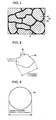
- FIG. 1 is an enlarged schematic view showing a dust core produced by using a soft magnetic material according to a first embodiment of the present invention.
- the dust core produced by using the soft magnetic material of this embodiment includes a plurality of composite magnetic particles 30 each composed of a metal magnetic particle 10 and an insulating coating 20 covering the surface of the metal magnetic particle 10.
- the plurality of composite magnetic particles 30 aggregate, for example, by means of an organic substance 40 disposed between the composite magnetic particles 30 or by means of engagement of irregularities that are present on the composite magnetic particles 30.
- Each of the plurality of composite magnetic particles 30 may further include a protective coating (not shown) covering the insulating coating 20.
- the organic substance 40 is not essential.
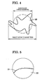
- Figure 2 is a plan view that schematically shows a single composite magnetic particle included in the soft magnetic material according to the first embodiment of the present invention.
- the composite magnetic particle 30 of the soft magnetic material of the present invention has a ratio of the maximum diameter to the equivalent circle diameter of more than 1.0 and 1.3 or less and a specific surface area of 0.10 m 2 /g or more.
- the maximum diameter, the equivalent circle diameter and the specific surface area of the composite magnetic particle 30 are defined by the following methods.
- the shape of the composite magnetic particle 30 is determined by an optical method (for example, observation with an optical microscope), and the maximum diameter is defined as the length of the part constituting the maximum particle diameter.
- the equivalent circle diameter of the composite magnetic particle 30 the shape of the composite magnetic particle 30 is determined by an optical method (for example, observation with an optical microscope), a surface area S of the composite magnetic particle 30 when viewed two-dimensionally is measured, and the equivalent circle diameter is calculated using Eq. (1):
- Equivalent circle diameter 2 ⁇ ⁇ surface area S / ⁇ ⁇ ⁇ 1 / 2 That is, as shown in Fig. 3, when a composite magnetic particle has a spherical shape, the ratio of the maximum diameter to the equivalent circle diameter is 1. As shown in Fig. 4, when a composite magnetic particle has larger projecting portions, the above ratio becomes higher.
- the specific surface area of the composite magnetic particle 30 is measured by a BET method. More specifically, an inert gas whose adsorption occupancy area is known is adsorbed on the surfaces of composite magnetic particles at the temperature of liquid nitrogen. The specific surface area of the composite magnetic particles is determined from the amount of adsorption.
- Figure 5 is an enlarged view of part III in Fig. 2.
- a large number of fine irregularities 31 of the order of about 1/100 of the particle diameter are formed on the surface of the composite magnetic particle 30.
- the composite magnetic particles 30 aggregate by means of engagement of these irregularities 31.
- the average particle diameter of the composite magnetic particles 30 is preferably in the range of 5 to 300 ⁇ m.
- the average particle diameter of the composite magnetic particles 30 is 5 ⁇ m or more, the metal is not easily oxidized, and thus a decrease in magnetic properties of the soft magnetic material can be suppressed.
- the average particle diameter of the composite magnetic particles 30 is 300 ⁇ m or less, a decrease in compressibility of a mixed powder can be suppressed during pressure molding. Consequently, the density of a compact produced by the pressure molding is not decreased, thus preventing difficulty in handling.
- the average particle diameter mentioned here means a particle diameter of a particle at which the cumulative sum of the masses of particles determined by adding the masses of particles starting from the smallest particle diameter reaches 50% in a histogram of particle diameters measured by means of a sieve method, that is, a 50% cumulative mass average particle diameter D.
- the metal magnetic particles 10 are made of, for example, Fe, an Fe-Si alloy, an Fe-N (nitrogen) alloy, an Fe-Ni (nickel) alloy, an Fe-C (carbon) alloy, an Fe-B (boron) alloy, an Fe-Co (cobalt) alloy, an Fe-P alloy, an Fe-Ni-Co alloy, an Fe-Cr (chromium) alloy, or an Fe-Al-Si alloy.
- the metal magnetic particles 10 may be made of a metal element or an alloy as long as the metal magnetic particles 10 contain Fe as a main component.
- the insulating coating 20 functions as an insulating layer disposed between the metal magnetic particles 10.
- the electrical resistivity p of a dust core produced by molding the resulting soft magnetic material under pressure can be increased. Accordingly, the flow of eddy currents between the metal magnetic particles 10 can be suppressed, thereby reducing eddy-current loss the dust core.
- the insulating coating 20 is made of an insulating substance such as a metal oxide, a metal nitride, a metal carbide, a metal phosphate compound, a metal borate compound, or a metal silicate compound each containing Fe, Al, Ca, Mn, Zn, Mg, V, Cr, Y, Ba, Sr, or a rare earth element as a metal.
- an insulating substance such as a metal oxide, a metal nitride, a metal carbide, a metal phosphate compound, a metal borate compound, or a metal silicate compound each containing Fe, Al, Ca, Mn, Zn, Mg, V, Cr, Y, Ba, Sr, or a rare earth element as a metal.
- the thickness of the insulating coating 20 is preferably in the range of 0.005 to 20 ⁇ m.
- the thickness of the insulating coating 20 is 0.005 ⁇ m or more, the generation of a tunneling current can be prevented, and energy loss due to an eddy current can be effectively suppressed.
- the thickness of the insulating coating 20 is 20 ⁇ m or less, the ratio of the insulating coating 20 to the soft magnetic material is not excessively high, thus preventing a marked decrease in the magnetic flux density of a dust core produced by molding the resulting soft magnetic material under pressure.
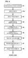
- Figure 6 is a process drawing that sequentially shows the steps of the method of producing the dust core according to the first embodiment of the present invention.
- a base powder composed of metal magnetic particles 10 that contain Fe as a main component and that are made of, for example, pure iron having a purity of 99.8% or more, Fe, an Fe-Si alloy, or an Fe-Co alloy is prepared (step S1).
- the average particle diameter of the metal magnetic particles 10 when the average particle diameter of the metal magnetic particles 10 is in the range of 5 to 300 ⁇ m, the average particle diameter of the composite magnetic material 30 of the produced soft magnetic material can be in the range of 5 to 300 ⁇ m. This is because the thickness of the insulating coating 20 is negligible compared with the particle diameter of each of the metal magnetic particles 10, and the particle diameter of each of the composite magnetic particles 30 and the particle diameter of each of the corresponding metal magnetic particles 10 are substantially the same.
- the metal magnetic particles 10 may be a gas-atomized powder or a water-atomized powder.
- the gas-atomized powder is a powder produced by atomizing a molten metal of a material to be formed into metal magnetic particles with a high-pressure gas, and then rapidly cooling with a gas.
- the water-atomized powder is a powder produced by atomizing a molten metal of a material to be formed into metal magnetic particles into water with a high-pressure water stream.
- the surface layer of the metal magnetic particles 10 is made smooth (step S1a). More specifically, the surface of the soft magnetic material is worn out with a ball mill to remove the projecting portions on the surfaces of the metal magnetic particles 10. As the processing time with the ball mill increases, the projecting portions are removed to a greater extent and the shape of the metal magnetic particles 10 becomes closer to being spherical.
- the processing time with the ball mill is, for example, in the range of 30 to 60 minutes, metal magnetic particles 10 having a ratio of the maximum diameter to the equivalent circle diameter of more than 1.0 and 1.3 or less can be obtained.
- each of the metal magnetic particles 10 When the metal magnetic particles 10 are composed of a gas-atomized powder, each of the metal magnetic particles 10 originally has a substantially spherical shape and has a ratio of the maximum diameter to the equivalent circle diameter of more than 1.0 and 1.3 or less. Accordingly, this spheroidizing treatment may be omitted.
- the metal magnetic particles 10 are heat-treated at a temperature of 400°C or higher and lower than the melting point of the particles (step S2).
- a large number of distortions (dislocations and defects) are present inside the metal magnetic particles 10 before heat treatment. Accordingly, by heat-treating the metal magnetic particles 10, these distortions can be reduced.
- the temperature of the heat treatment is more preferably 700°C or higher and lower than 900°C. When the heat treatment is performed in this temperature range, a satisfactory effect of removing the distortions can be obtained while sintering between the particles can be prevented. This heat treatment may be omitted.
- step S3 irregularities are formed on the surfaces of the metal magnetic particles 10 (step S3). More specifically, the metal magnetic particles 10 are immersed in an aqueous sulfuric acid solution having a predetermined concentration. Accordingly, the surfaces of the metal magnetic particles 10 are etched by sulfuric acid, and irregularities are formed on the surfaces of the metal magnetic particles 10.
- the immersion time in the aqueous sulfuric acid solution is, for example, 20 minutes or more, the specific surface area of the metal magnetic particles 10 becomes 0.10 m 2 /g or more.
- an insulating coating 20 is formed on the surfaces of the metal magnetic particles 10 by immersing the metal magnetic particles 10 in, for example, an aqueous aluminum phosphate solution (step S4).
- a protective coating made of, for example, a silicone resin is formed (step S5). More specifically, a silicone resin dissolved in an organic solvent is mixed with or atomized on the metal magnetic particles 10 coated with the insulating coating 20. The metal magnetic particles 10 are then dried to remove the solvent. The formation of this protective coating may be omitted.
- the soft magnetic material of this embodiment is produced. Furthermore, by performing the following production steps, the dust core of this embodiment is produced.
- the resulting composite magnetic particles 30 are mixed with an organic substance 40 used as a binder (step S6).
- the mixing method is not particularly limited. For example, a dry mixing using a V-type mixer or a wet mixing using a mixer-type blending machine may be employed. Consequently, the plurality of composite magnetic particles 30 are aggregated by the presence of the organic substance 40. This mixing with a binder may be omitted.
- Examples of the organic substance 40 include thermoplastic resins such as thermoplastic polyimides, thermoplastic polyamides, thermoplastic polyamideimides, polyphenylene sulfides, polyamideimides, polyethersulfones, polyetherimides, and polyetheretherketones; non-thermoplastic resins such as high-molecular-weight polyethylenes, fully aromatic polyesters, and fully aromatic polyimides; and higher fatty acids such as zinc stearate, lithium stearate, calcium stearate, lithium palmitate, calcium palmitate, lithium oleate, and calcium oleate. These may be used in combinations.
- thermoplastic resins such as thermoplastic polyimides, thermoplastic polyamides, thermoplastic polyamideimides, polyphenylene sulfides, polyamideimides, polyethersulfones, polyetherimides, and polyetheretherketones
- non-thermoplastic resins such as high-molecular-weight polyethylenes, fully aromatic polyesters, and fully aromatic polyimides
- higher fatty acids
- the powder of the resulting soft magnetic material is supplied in a die and molded under a pressure, for example, in the range of 390 to 1,500 (MPa) (step S7). Accordingly, a compact in which the powder composed of the metal magnetic particles 10 is compressed is prepared.
- the atmosphere during the pressure molding is preferably an inert gas atmosphere or a reduced pressure atmosphere. In this case, oxidation of the mixed powder by oxygen in air can be suppressed.
- the compact prepared by the pressure molding is heat-treated at a temperature in the range of 200°C to 900°C (step S8). Since a large number of distortions and dislocations are generated inside the compact formed by pressure molding, the distortions and dislocations can be removed by the heat treatment. By performing the above-described steps, the dust core shown in Fig. 1 is produced.
- the strength of a compact can be improved while eddy-current loss is decreased. The reason for this will now be described.
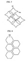
- FIG. 7 is a schematic view showing an aggregated state of composite magnetic particles composed of a water-atomized powder.
- composite magnetic particles 130a produced from a water-atomized powder each include a large number of projecting portions 131. Accordingly, since the composite magnetic particles 130a are engaged with each other by the projecting portions, aggregation between the composite magnetic particles 130a can be enhanced to improve the strength of the resulting compact. However, in the composite magnetic particles 130a, stress is concentrated on the projecting portions during pressure molding, thereby breaking an insulating coating. As a result, eddy-current loss is increased.
- Figure 8 is a schematic view showing an aggregated state of composite magnetic particles composed of a gas-atomized powder.
- composite magnetic particles 130b produced from a gas-atomized powder include little projecting portions. Accordingly, in the composite magnetic particles 130b, the breakage of an insulating coating can be prevented during pressure molding, and thus eddy-current loss can be decreased. However, since the composite magnetic particles 130a do not have projecting portions, aggregation between the composite magnetic particles 130b is decreased, resulting in a decrease in the strength of the resulting compact.
- the composite magnetic particles 30 included in the soft magnetic material of the present invention have a shape in which a large number of fine irregularities 31 of the order of about 1/100 of the particle diameter are formed. Accordingly, aggregation between the composite magnetic particles 30 can be enhanced by the large number of irregularities 31, thereby improving the strength of the resulting compact.
- the projections of the irregularities 31 of the composite magnetic particles 30 are smaller than the projecting portions 131 of the composite magnetic particles 130a composed of a water-atomized powder. Therefore, the breakage of an insulating coating can be suppressed during pressure molding, and thus eddy-current loss can be decreased.
- the insulating coating of the composite magnetic particles 30 included in the soft magnetic material of the present invention is not easily broken during pressure molding compared with that of composite magnetic particles obtained from known water-atomized powders or gas-atomized powders, even when the heat treatment after pressure molding is performed at a high temperature (for example, a temperature higher than 500°C), the breakage of the insulating coating due to heat does not easily occur. Accordingly, distortions in the metal magnetic particles can be efficiently removed while an increase in eddy-current loss is suppressed. Thus, both hysteresis loss and eddy-current loss of the soft magnetic material can be decreased.
- soft magnetic materials of samples A1 to A13 and samples B1 to B13 were prepared using substantially the same production method as that described in the first embodiment.
- the ratio of the maximum diameter to the equivalent circle diameter (maximum diameter/equivalent circle diameter) and the specific surface area (m 2 /g) of composite magnetic particles of the soft magnetic materials were examined.
- a water-atomized powder (samples A1 to A12 and samples B1 to B12) and a gas-atomized powder (samples A13 and B13) each having a particle diameter in the range of 50 to 150 ⁇ m and a purity of 99.8% or more were prepared as metal magnetic particles.
- the metal magnetic particles composed of the water-atomized powder were then spheroidized with a ball mill.
- a planetary ball mill P-5 manufactured by Fritsch GmbH was used for the ball mill processing.
- a plurality types of metal magnetic particles in which a processing condition for the ball mill was different were prepared by changing the ball mill processing time in the range of 1 to 60 minutes. For comparison, metal magnetic particles that were not subjected to the ball mill processing were also prepared.
- the metal magnetic particles composed of the gas-atomized powder were not spheroidized.
- the metal magnetic particles for each sample were then heat-treated at 600°C in a hydrogen stream.
- the metal magnetic particles 10 to be formed into samples B1 to B13 were immersed in an aqueous sulfuric acid solution for 20 minutes to form irregularities on the surfaces of the metal magnetic particles.
- the aqueous sulfuric acid solution used was prepared by dissolving 0.75 g of H 2 SO 4 in 1 L of water relative to 1 kg of the metal magnetic particles and adjusting the pH of the aqueous solution to about 2.0.
- the above treatment with the aqueous sulfuric acid solution was not performed in samples A1 to A13.
- the metal magnetic particles for each sample were immersed in an aqueous solution of a phosphate to form an insulating coating.
- the metal magnetic particles coated with the insulating coating were then mixed with a silicone resin (trade name "TSR116", manufactured by GE Toshiba Silicones Co., Ltd.).
- TSR116 trade name "TSR116”
- the silicone resin was then thermally cured by heating the mixture in air at 150°C for one hour to form a protective coating.
- soft magnetic materials were prepared.
- samples A1 to A13 and samples B1 to B 13 samples that satisfied a ratio of the maximum diameter to the equivalent circle diameter of the composite magnetic particles of more than 1.0 and 1.3 or less and a specific surface area of 0.10 m 2 /g or more were only samples B9 to B13. Accordingly, samples B9 to B13 corresponded to samples of the present invention.
- dust cores were prepared using samples A1 to A13 and samples B1 to B 13 prepared in Example 1 and magnetic properties of the dust cores were evaluated.
- Example 1 Each of the soft magnetic materials prepared in Example 1 was molded under a surface pressure in the range of 10 to 13 ton/cm 2 to prepare a ringshaped compact (outer diameter: 34 mm, inner diameter 20 mm, thickness: 5 mm) having a density of 7.60 g/cm 3 .
- the compact was then heat-treated in a nitrogen stream atmosphere at 500°C for one hour.
- samples A6 to A13 and samples B8 to B13 even when the compacts were heat-treated at a temperature higher than 500°C, the insulating coating was not broken. Therefore, heat treatment was also performed at an optimum temperature exceeding 500°C. Thus, dust cores were prepared.
- Hysteresis loss, eddy-current loss, and core loss of the dust cores prepared above were measured with a BH curve tracer.
- the hysteresis loss and the eddy-current loss were separated as follows.
- the frequency curve of the core loss was fitted by a least squares method using the following three equations to calculate a hysteresis loss coefficient and an eddy-current loss coefficient. The results are shown in Table II.
- the insulating coating is not broken.
- distortions in the metal magnetic particles can be effectively removed while an increase in the eddy-current loss is suppressed.
- hysteresis loss of the soft magnetic materials can be markedly decreased.
- samples A9 to A13 and samples B9 to B13 when the strengths of compacts of samples having the same ratio of the maximum diameter to the equivalent circle diameter of the composite magnetic particles (samples having the same reference number) were compared, for example, the strength of the compact of sample A9 was 53 MPa, whereas that of sample B9 was 96 MPa. Similarly, the strength of the compact of sample A10 was 43 MPa, whereas that of sample B10 was 92 MPa. The strength of the compact of sample A11 was 44 MPa, whereas that of sample B11 was 93 MPa. The strength of the compact of sample A12 was 38 MPa, whereas that of sample B12 was 89 MPa. Furthermore, the strength of the compact of sample A13 was 26 MPa, whereas that of sample B13 was 72 MPa. These results showed that the soft magnetic materials of the present invention could improve the strengths of the resulting compacts.
- a soft magnetic material and a dust core of the present invention are generally used for, for example, a motor core, a solenoid valve, a reactor, and an electromagnetic component.
Landscapes
- Engineering & Computer Science (AREA)
- Power Engineering (AREA)
- Manufacturing & Machinery (AREA)
- Chemical & Material Sciences (AREA)
- Dispersion Chemistry (AREA)
- Soft Magnetic Materials (AREA)
- Powder Metallurgy (AREA)
Applications Claiming Priority (2)
| Application Number | Priority Date | Filing Date | Title |
|---|---|---|---|
| JP2005118581A JP4650073B2 (ja) | 2005-04-15 | 2005-04-15 | 軟磁性材料の製造方法、軟磁性材料および圧粉磁心 |
| PCT/JP2006/304573 WO2006112197A1 (ja) | 2005-04-15 | 2006-03-09 | 軟磁性材料および圧粉磁心 |
Publications (2)
| Publication Number | Publication Date |
|---|---|
| EP1870911A1 true EP1870911A1 (de) | 2007-12-26 |
| EP1870911A4 EP1870911A4 (de) | 2010-01-27 |
Family
ID=37114931
Family Applications (1)
| Application Number | Title | Priority Date | Filing Date |
|---|---|---|---|
| EP06715444A Withdrawn EP1870911A4 (de) | 2005-04-15 | 2006-03-09 | Weichmagnetisches material und pulverkern |
Country Status (5)
| Country | Link |
|---|---|
| US (2) | US20080061264A1 (de) |
| EP (1) | EP1870911A4 (de) |
| JP (1) | JP4650073B2 (de) |
| CN (1) | CN101160633B (de) |
| WO (1) | WO2006112197A1 (de) |
Cited By (2)
| Publication number | Priority date | Publication date | Assignee | Title |
|---|---|---|---|---|
| EP3505276A4 (de) * | 2016-08-25 | 2020-07-29 | Whirlpool S.A. | Oberflächenbeschichtungsschichten mit ferromagnetischen teilchen zur herstellung von weichmagnetischen verbundwerkstoffen (smcs) |
| JP2023085967A (ja) * | 2021-12-09 | 2023-06-21 | 株式会社タムラ製作所 | 軟磁性粉末及び圧粉磁心 |
Families Citing this family (50)
| Publication number | Priority date | Publication date | Assignee | Title |
|---|---|---|---|---|
| JP4613622B2 (ja) * | 2005-01-20 | 2011-01-19 | 住友電気工業株式会社 | 軟磁性材料および圧粉磁心 |
| JP4654881B2 (ja) * | 2005-11-02 | 2011-03-23 | 住友電気工業株式会社 | 軟磁性材料を用いて製造された圧粉磁心 |
| JP2007324270A (ja) * | 2006-05-31 | 2007-12-13 | Toyota Motor Corp | 磁性粉末の製造方法および圧粉コアの製造方法 |
| US20080036566A1 (en) | 2006-08-09 | 2008-02-14 | Andrzej Klesyk | Electronic Component And Methods Relating To Same |
| JP2008308758A (ja) * | 2006-09-26 | 2008-12-25 | Mitsubishi Materials Corp | 高比抵抗を有しかつ低鉄損を有する複合軟磁性材を製造するための複合軟磁性鉄粉末 |
| JP5368686B2 (ja) * | 2007-09-11 | 2013-12-18 | 住友電気工業株式会社 | 軟磁性材料、圧粉磁心、軟磁性材料の製造方法、および圧粉磁心の製造方法 |
| JP2009117484A (ja) * | 2007-11-02 | 2009-05-28 | Tamura Seisakusho Co Ltd | 圧粉磁心の製造方法及び圧粉磁心 |
| CN101615465B (zh) * | 2008-05-30 | 2012-10-17 | 株式会社日立制作所 | 压粉磁体用软磁性粉末和使用其的压粉磁体 |
| US8487487B2 (en) * | 2008-07-15 | 2013-07-16 | Ethicon Endo-Surgery, Inc. | Magnetostrictive actuator of a medical ultrasound transducer assembly, and a medical ultrasound handpiece and a medical ultrasound system having such actuator |
| JP5202382B2 (ja) * | 2009-02-24 | 2013-06-05 | 株式会社神戸製鋼所 | 圧粉磁心用鉄基軟磁性粉末およびその製造方法、ならびに圧粉磁心 |
| JP4995222B2 (ja) * | 2009-04-09 | 2012-08-08 | 株式会社タムラ製作所 | 圧粉磁心及びその製造方法 |
| JP5232708B2 (ja) * | 2009-04-14 | 2013-07-10 | 株式会社タムラ製作所 | 圧粉磁心及びその製造方法 |
| JP5765907B2 (ja) * | 2009-11-09 | 2015-08-19 | 株式会社フェローテック | 磁性部材および電子部品 |
| US8723634B2 (en) | 2010-04-30 | 2014-05-13 | Taiyo Yuden Co., Ltd. | Coil-type electronic component and its manufacturing method |
| JP4866971B2 (ja) | 2010-04-30 | 2012-02-01 | 太陽誘電株式会社 | コイル型電子部品およびその製造方法 |
| JP2012107330A (ja) * | 2010-10-26 | 2012-06-07 | Sumitomo Electric Ind Ltd | 軟磁性粉末、造粒粉、圧粉磁心、電磁部品及び圧粉磁心の製造方法 |
| JP6081051B2 (ja) | 2011-01-20 | 2017-02-15 | 太陽誘電株式会社 | コイル部品 |
| JP2012238841A (ja) | 2011-04-27 | 2012-12-06 | Taiyo Yuden Co Ltd | 磁性材料及びコイル部品 |
| JP4906972B1 (ja) | 2011-04-27 | 2012-03-28 | 太陽誘電株式会社 | 磁性材料およびそれを用いたコイル部品 |
| JP2012238840A (ja) | 2011-04-27 | 2012-12-06 | Taiyo Yuden Co Ltd | 積層インダクタ |
| JP5336543B2 (ja) | 2011-04-28 | 2013-11-06 | 太陽誘電株式会社 | コイル部品 |
| JP5032711B1 (ja) | 2011-07-05 | 2012-09-26 | 太陽誘電株式会社 | 磁性材料およびそれを用いたコイル部品 |
| JP5048155B1 (ja) | 2011-08-05 | 2012-10-17 | 太陽誘電株式会社 | 積層インダクタ |
| JP5048156B1 (ja) | 2011-08-10 | 2012-10-17 | 太陽誘電株式会社 | 積層インダクタ |
| JP5280500B2 (ja) | 2011-08-25 | 2013-09-04 | 太陽誘電株式会社 | 巻線型インダクタ |
| JP5769549B2 (ja) | 2011-08-25 | 2015-08-26 | 太陽誘電株式会社 | 電子部品及びその製造方法 |
| JP5082002B1 (ja) | 2011-08-26 | 2012-11-28 | 太陽誘電株式会社 | 磁性材料およびコイル部品 |
| JP6091744B2 (ja) | 2011-10-28 | 2017-03-08 | 太陽誘電株式会社 | コイル型電子部品 |
| JP5960971B2 (ja) | 2011-11-17 | 2016-08-02 | 太陽誘電株式会社 | 積層インダクタ |
| JP6012960B2 (ja) | 2011-12-15 | 2016-10-25 | 太陽誘電株式会社 | コイル型電子部品 |
| JP6052960B2 (ja) | 2012-01-12 | 2016-12-27 | 株式会社神戸製鋼所 | 軟磁性鉄基粉末の製造方法 |
| JP2012199580A (ja) * | 2012-06-06 | 2012-10-18 | Sumitomo Electric Ind Ltd | 軟磁性複合材料の製造方法 |
| JP5445801B2 (ja) * | 2012-07-12 | 2014-03-19 | 住友電気工業株式会社 | リアクトル、及び昇圧回路 |
| JP5660164B2 (ja) * | 2013-06-28 | 2015-01-28 | 住友電気工業株式会社 | 軟磁性複合材料の製造方法 |
| KR101626659B1 (ko) * | 2013-07-04 | 2016-06-01 | 티디케이가부시기가이샤 | 연자성체 조성물 및 그 제조 방법, 자심, 및, 코일형 전자 부품 |
| JP2014075596A (ja) * | 2013-11-25 | 2014-04-24 | Sumitomo Electric Ind Ltd | リアクトル |
| JP2015103719A (ja) * | 2013-11-26 | 2015-06-04 | 住友電気工業株式会社 | 圧粉磁心、コイル部品、及び圧粉磁心の製造方法 |
| JP5874769B2 (ja) * | 2014-03-12 | 2016-03-02 | 住友電気工業株式会社 | 軟磁性複合材料、及びリアクトル |
| JP6024927B2 (ja) * | 2014-11-12 | 2016-11-16 | 住友電気工業株式会社 | 軟磁性複合材料 |
| JP5881027B1 (ja) * | 2015-03-16 | 2016-03-09 | パナソニックIpマネジメント株式会社 | 樹脂シート、樹脂シートの製造方法、インダクタ部品 |
| JP6679305B2 (ja) * | 2015-12-28 | 2020-04-15 | Dowaエレクトロニクス株式会社 | 磁性コンパウンドとその製造方法並びに電子部品、アンテナ |
| JP2016149559A (ja) * | 2016-03-03 | 2016-08-18 | 住友電気工業株式会社 | 軟磁性複合材料 |
| US10953464B2 (en) * | 2016-11-22 | 2021-03-23 | The Johns Hopkins University | Empowering additive manufacturing metals and alloys against localized three-dimensional corrosion |
| KR20180061508A (ko) * | 2016-11-29 | 2018-06-08 | 현대자동차주식회사 | 연자성 분말 제조방법 |
| CN110681856B (zh) * | 2018-07-06 | 2021-07-27 | 安泰(霸州)特种粉业有限公司 | 一种水雾化软磁合金粉末球化处理方法 |
| CN109193977B (zh) * | 2018-09-26 | 2020-04-14 | 浙江宝捷机电有限公司 | 一种用于发电机铁芯的磁性材料及其制备方法 |
| JP2021034609A (ja) * | 2019-08-27 | 2021-03-01 | パナソニック株式会社 | 圧粉磁心およびその製造方法 |
| JP2020077845A (ja) * | 2018-11-01 | 2020-05-21 | パナソニック株式会社 | 圧粉磁心およびその製造方法 |
| KR102198532B1 (ko) | 2019-06-25 | 2021-01-06 | 삼성전기주식회사 | 코일 부품 |
| JP7375469B2 (ja) * | 2019-10-30 | 2023-11-08 | セイコーエプソン株式会社 | 絶縁体被覆磁性合金粉末粒子、圧粉磁心、およびコイル部品 |
Family Cites Families (11)
| Publication number | Priority date | Publication date | Assignee | Title |
|---|---|---|---|---|
| JPH01294804A (ja) * | 1988-02-25 | 1989-11-28 | Tdk Corp | 圧粉コア用強磁性粉末および圧粉コア |
| DE69031250T2 (de) * | 1989-06-09 | 1997-12-04 | Matsushita Electric Ind Co Ltd | Magnetisches Material |
| JPH03278407A (ja) * | 1989-06-09 | 1991-12-10 | Matsushita Electric Ind Co Ltd | 複合磁性材料 |
| US5294374A (en) * | 1992-03-20 | 1994-03-15 | Leviton Manufacturing Co., Inc. | Electrical overstress materials and method of manufacture |
| JPH07245209A (ja) * | 1994-03-02 | 1995-09-19 | Tdk Corp | 圧粉コアおよびその製造方法 |
| US5756162A (en) * | 1995-08-31 | 1998-05-26 | Samsung Electro-Mechanics Co., Ltd. | Method for manufacturing sendust core powder |
| JP4336810B2 (ja) * | 2001-08-15 | 2009-09-30 | 大同特殊鋼株式会社 | 圧粉磁心 |
| JP2003086415A (ja) * | 2001-09-12 | 2003-03-20 | Aisin Seiki Co Ltd | モータ又は電磁アクチュエータ用軟磁性粒子、モータ又は電磁アクチュエータ用軟磁性粒子の製造方法、モータ又は電磁アクチュエータ用軟磁性成形体、モータ又は電磁アクチュエータ用軟磁性成形体の製造方法 |
| JP2003202704A (ja) * | 2001-12-28 | 2003-07-18 | Toda Kogyo Corp | 磁性カラートナー用複合磁性粒子粉末及び該複合磁性粒子粉末を用いた磁性カラートナー、磁性カラートナーを用いた磁気潜像現像方法及び静電荷像現像方法 |
| JP2004211129A (ja) * | 2002-12-27 | 2004-07-29 | Jfe Steel Kk | 圧粉磁心用金属粉末およびそれを用いた圧粉磁心 |
| US20060188755A1 (en) * | 2005-02-23 | 2006-08-24 | Meiji University Legal Person | Spinel-type ferrimagnetic particles process for producing the same, and magnetic recording medium using the same |
-
2005
- 2005-04-15 JP JP2005118581A patent/JP4650073B2/ja not_active Expired - Fee Related
-
2006
- 2006-03-09 EP EP06715444A patent/EP1870911A4/de not_active Withdrawn
- 2006-03-09 US US11/911,657 patent/US20080061264A1/en not_active Abandoned
- 2006-03-09 WO PCT/JP2006/304573 patent/WO2006112197A1/ja not_active Ceased
- 2006-03-09 CN CN2006800120187A patent/CN101160633B/zh not_active Expired - Fee Related
-
2010
- 2010-11-01 US US12/917,243 patent/US20110045174A1/en not_active Abandoned
Cited By (2)
| Publication number | Priority date | Publication date | Assignee | Title |
|---|---|---|---|---|
| EP3505276A4 (de) * | 2016-08-25 | 2020-07-29 | Whirlpool S.A. | Oberflächenbeschichtungsschichten mit ferromagnetischen teilchen zur herstellung von weichmagnetischen verbundwerkstoffen (smcs) |
| JP2023085967A (ja) * | 2021-12-09 | 2023-06-21 | 株式会社タムラ製作所 | 軟磁性粉末及び圧粉磁心 |
Also Published As
| Publication number | Publication date |
|---|---|
| JP2006302958A (ja) | 2006-11-02 |
| WO2006112197A1 (ja) | 2006-10-26 |
| CN101160633B (zh) | 2010-04-14 |
| JP4650073B2 (ja) | 2011-03-16 |
| US20110045174A1 (en) | 2011-02-24 |
| CN101160633A (zh) | 2008-04-09 |
| EP1870911A4 (de) | 2010-01-27 |
| US20080061264A1 (en) | 2008-03-13 |
Similar Documents
| Publication | Publication Date | Title |
|---|---|---|
| EP1870911A1 (de) | Weichmagnetisches material und pulverkern | |
| EP1840907B1 (de) | Weichmagnetisches material und pulverkern | |
| EP1808242B1 (de) | Verfahren zur herstellung eines mit einem mg-haltigen oxidierten film beschichteten weichmagnetischen metallpulvers und verfahren zur herstellung eines weichmagnetischen verbundmaterials unter verwendung des pulvers | |
| JP4654881B2 (ja) | 軟磁性材料を用いて製造された圧粉磁心 | |
| JP5470683B2 (ja) | 圧粉磁心用金属粉末および圧粉磁心の製造方法 | |
| JP4535070B2 (ja) | 軟磁性材料ならびに圧粉磁心およびその製造方法 | |
| US20110104476A1 (en) | Soft magnetic material, motor core, transformer core, and method for manufacturing soft magnetic material | |
| JP2005286145A (ja) | 軟磁性材料の製造方法、軟磁性粉末および圧粉磁心 | |
| EP1716946A1 (de) | Weichmagnetisches material und pulverkern | |
| JPH02290002A (ja) | Fe―Si系合金圧粉磁心およびその製造方法 | |
| JP2009235517A (ja) | 圧粉磁心用金属粉末および圧粉磁心の製造方法 | |
| JP4507663B2 (ja) | 軟磁性材料の製造方法、軟磁性粉末および圧粉磁心 | |
| JPWO2005013294A1 (ja) | 軟磁性材料、圧粉磁心、トランスコア、モータコアおよび圧粉磁心の製造方法 | |
| JP2005079511A (ja) | 軟磁性材料およびその製造方法 | |
| US7601229B2 (en) | Process for producing soft magnetism material, soft magnetism material and powder magnetic core | |
| JP2005015914A (ja) | 複合磁性材料およびその製造方法 | |
| JP2007231330A (ja) | 圧粉磁心用金属粉末および圧粉磁心の製造方法 | |
| EP1486990A2 (de) | Magnetisches Verbundmaterial und Verfahren zu seiner Herstellung | |
| EP1662517A1 (de) | Weichmagnetisches material und herstellungsverfahren dafür | |
| KR102821782B1 (ko) | 30 중량% 이하의 니켈을 포함하는 연자성 조성물, 이를 포함하는 연자성 코어 및 그 제조 방법 | |
| JP2005142522A (ja) | 軟磁性材料の製造方法、軟磁性材料および圧粉磁心 | |
| JPH10324960A (ja) | 軟磁性燒結金属とその製造方法およびこれを用いた磁性部品 | |
| JP2006049789A (ja) | 軟磁性材料、圧粉磁心および圧粉磁心の製造方法 | |
| JP2005142533A (ja) | 軟磁性材料および圧粉磁心 |
Legal Events
| Date | Code | Title | Description |
|---|---|---|---|
| PUAI | Public reference made under article 153(3) epc to a published international application that has entered the european phase |
Free format text: ORIGINAL CODE: 0009012 |
|
| 17P | Request for examination filed |
Effective date: 20071010 |
|
| AK | Designated contracting states |
Kind code of ref document: A1 Designated state(s): DE FR |
|
| DAX | Request for extension of the european patent (deleted) | ||
| RBV | Designated contracting states (corrected) |
Designated state(s): DE FR |
|
| A4 | Supplementary search report drawn up and despatched |
Effective date: 20100104 |
|
| RIC1 | Information provided on ipc code assigned before grant |
Ipc: H01F 41/02 20060101ALI20091221BHEP Ipc: H01F 1/20 20060101ALI20091221BHEP Ipc: H01F 1/24 20060101AFI20061110BHEP Ipc: B22F 1/02 20060101ALI20091221BHEP |
|
| STAA | Information on the status of an ep patent application or granted ep patent |
Free format text: STATUS: THE APPLICATION HAS BEEN WITHDRAWN |
|
| 18W | Application withdrawn |
Effective date: 20160824 |