EP1871594B1 - Beschleunigungsmittel für voraufgebrachte klebstoffe - Google Patents
Beschleunigungsmittel für voraufgebrachte klebstoffe Download PDFInfo
- Publication number
- EP1871594B1 EP1871594B1 EP06721110.2A EP06721110A EP1871594B1 EP 1871594 B1 EP1871594 B1 EP 1871594B1 EP 06721110 A EP06721110 A EP 06721110A EP 1871594 B1 EP1871594 B1 EP 1871594B1
- Authority
- EP
- European Patent Office
- Prior art keywords
- activator
- adhesive
- projections
- face
- linear
- Prior art date
- Legal status (The legal status is an assumption and is not a legal conclusion. Google has not performed a legal analysis and makes no representation as to the accuracy of the status listed.)
- Expired - Lifetime
Links
Images




Classifications
-
- C—CHEMISTRY; METALLURGY
- C09—DYES; PAINTS; POLISHES; NATURAL RESINS; ADHESIVES; COMPOSITIONS NOT OTHERWISE PROVIDED FOR; APPLICATIONS OF MATERIALS NOT OTHERWISE PROVIDED FOR
- C09J—ADHESIVES; NON-MECHANICAL ASPECTS OF ADHESIVE PROCESSES IN GENERAL; ADHESIVE PROCESSES NOT PROVIDED FOR ELSEWHERE; USE OF MATERIALS AS ADHESIVES
- C09J5/00—Adhesive processes in general; Adhesive processes not provided for elsewhere, e.g. relating to primers
- C09J5/06—Adhesive processes in general; Adhesive processes not provided for elsewhere, e.g. relating to primers involving heating of the applied adhesive
-
- C—CHEMISTRY; METALLURGY
- C08—ORGANIC MACROMOLECULAR COMPOUNDS; THEIR PREPARATION OR CHEMICAL WORKING-UP; COMPOSITIONS BASED THEREON
- C08J—WORKING-UP; GENERAL PROCESSES OF COMPOUNDING; AFTER-TREATMENT NOT COVERED BY SUBCLASSES C08B, C08C, C08F, C08G or C08H
- C08J3/00—Processes of treating or compounding macromolecular substances
- C08J3/24—Crosslinking, e.g. vulcanising, of macromolecules
- C08J3/241—Preventing premature crosslinking by physical separation of components, e.g. encapsulation
-
- F—MECHANICAL ENGINEERING; LIGHTING; HEATING; WEAPONS; BLASTING
- F16—ENGINEERING ELEMENTS AND UNITS; GENERAL MEASURES FOR PRODUCING AND MAINTAINING EFFECTIVE FUNCTIONING OF MACHINES OR INSTALLATIONS; THERMAL INSULATION IN GENERAL
- F16B—DEVICES FOR FASTENING OR SECURING CONSTRUCTIONAL ELEMENTS OR MACHINE PARTS TOGETHER, e.g. NAILS, BOLTS, CIRCLIPS, CLAMPS, CLIPS OR WEDGES; JOINTS OR JOINTING
- F16B39/00—Locking of screws, bolts or nuts
- F16B39/22—Locking of screws, bolts or nuts in which the locking takes place during screwing down or tightening
- F16B39/28—Locking of screws, bolts or nuts in which the locking takes place during screwing down or tightening by special members on, or shape of, the nut or bolt
- F16B39/34—Locking by deformable inserts or like parts
-
- C—CHEMISTRY; METALLURGY
- C08—ORGANIC MACROMOLECULAR COMPOUNDS; THEIR PREPARATION OR CHEMICAL WORKING-UP; COMPOSITIONS BASED THEREON
- C08F—MACROMOLECULAR COMPOUNDS OBTAINED BY REACTIONS ONLY INVOLVING CARBON-TO-CARBON UNSATURATED BONDS
- C08F212/00—Copolymers of compounds having one or more unsaturated aliphatic radicals, each having only one carbon-to-carbon double bond, and at least one being terminated by an aromatic carbocyclic ring
-
- C—CHEMISTRY; METALLURGY
- C08—ORGANIC MACROMOLECULAR COMPOUNDS; THEIR PREPARATION OR CHEMICAL WORKING-UP; COMPOSITIONS BASED THEREON
- C08F—MACROMOLECULAR COMPOUNDS OBTAINED BY REACTIONS ONLY INVOLVING CARBON-TO-CARBON UNSATURATED BONDS
- C08F220/00—Copolymers of compounds having one or more unsaturated aliphatic radicals, each having only one carbon-to-carbon double bond, and only one being terminated by only one carboxyl radical or a salt, anhydride ester, amide, imide or nitrile thereof
Definitions
- the present invention is directed to a novel activator method and apparatus for use in activating or re-activating adhesive and sealant compositions that have been pre-applied to a bonding surface or a substrate prior to mating said bonding surface with the surface or substrate to which it is to be bonded.
- the activator means is a heated activator means for use with pre-applied heat activated/re-activated adhesive and sealant compositions wherein the heat of the activator means transforms the adhesive or sealant into a flowable state and the features of the activator face of the activator means serve to lift the flowable adhesive or sealant from the substrate surface, collect and then redeposit the same on the substrate surface in the area of the intended bondline in a defined profile.
- the activator means has an activator that is not heated or, if heated, provides minimal heat, and whose activator face has features that are capable of lifting the adhesive from the surface of the substrate to which it is pre-applied, mixing and collecting the pre-applied adhesive material and then re-depositing the same on the substrate surface in the area of the intended bondline.
- the activator means is employed with pre-applied, two-part, curable or polymerizable adhesive or sealant compositions, especially encapsulated compositions, and has features on the activator face that are capable of intimately mixing the two parts to activate the cure or polymerization of the composition before re-depositing the activated composition on the substrate surface in the area of the intended bondline.
- the present invention is also directed to industrial bonding systems and apparatus that incorporate said activator means, especially systems and apparatus for high-speed industrial, automated bonding applications as well as bonding methods employing the aforementioned activator means.
- Multi-part adhesive and sealant compositions are widely known and commercially available for both consumer and industrial or commercial use. These compositions are typically characterized as being reactive systems wherein cure or polymerization is initiated once all of the components of the curable composition are brought into intimate contact with one another.
- the most common multi-part adhesive and sealant compositions are two-part systems.
- Two-part adhesive and sealant compositions take many forms and can be employed in numerous ways.
- an adhesive or sealant composition may comprise a first part, Part A, which includes a liquid curable component, and a second part, Part B, which includes an activator in an appropriate solvent, which activator, in the presence of Part A, initiates or effectuates cure or polymerization of the liquid curable component.
- Part A which includes a liquid curable component
- Part B which includes an activator in an appropriate solvent, which activator, in the presence of Part A, initiates or effectuates cure or polymerization of the liquid curable component.
- one or both of the surfaces to be bonded is pretreated or primed
- both Parts A and B may comprise the same or a different liquid curable component with Part A also containing an activator which is, by itself, non-reactive with the liquid curable component of that part, but which is reactive when mixed with Part B.
- the activator may be a chemical additive such as an initiator, accelerator, catalyst, etc., which effectuates polymerization or cure but does not itself become chemically incorporated into the cured or polymerized polymer (though it may be physically entrained therein) or it may be a component co-polymerizable with the liquid curable component of Part B, as for example a cross-linking agent or hardener.
- the activator may be a chemical additive such as an initiator, accelerator, catalyst, etc., which effectuates polymerization or cure but does not itself become chemically incorporated into the cured or polymerized polymer (though it may be physically entrained therein) or it may be a component co-polymerizable with the liquid curable component of Part B, as for example a cross
- two-part epoxy adhesive and sealant compositions often are found in the form of ribbons, strings, beads, etc. of the two parts in a putty-like state, extruded in a side-by-side or concentric relationship.
- cure or hardening is initiated upon intimate mixing of the two components.
- the former allows for continuous, or nearly so, dispensing so long as the reservoirs are replenished.
- concerns arise relative to clogging of the dispenser nozzle due to cure of the two-part compositions in the mixer head or at the nozzle orifice, particularly in the event of a shut down or temporary stoppage of the assembly line.
- the use of the cartridge is especially beneficial in those systems where it is impractical to employ large containers or the containers are unable to be located proximate to the dispenser nozzle. Further, with these systems one has the benefit of being able to dispose of the spent cartridges and avoid concerns of contamination, set-up or cure of the large reservoirs.
- the unspent cartridge is merely replaced with a new cartridge; whereas, if a problem arises with the large reservoir systems, the reservoirs must be emptied and cleaned and the dispensing system purged before dispensing can be resumed.
- cartridges one also has the possibility of integrating the nozzle or mixer head in the cartridge assembly. Thus, the nozzle or mixer head is replaced with each replacement of the cartridge. If a problem should arise where the nozzle or mixer head is clogged, one merely replaces the whole cartridge system and gets on with the assembly operation. The only loss is the unspent materials in the cartridge and a minimal delay in the assembly line process.
- thermoplastic including cooled hot melt
- thermoset adhesive materials that are activated or re-activated, as the case may be, upon exposure to, among others, high temperatures, irradiation (e.g., UV, IR, etc.), electromagnetic fields (e.g., RF, UHF, microwave, etc.) and/or ultrasound.
- irradiation e.g., UV, IR, etc.
- electromagnetic fields e.g., RF, UHF, microwave, etc.
- ultrasound ultrasound
- each presents concerns relative to the generation of the necessary energy to activate or re-activate the adhesive, not only with respect to the substrate being acted upon but also the associated equipment proximate to the activation station of the assembly line as well as other general health, safety and environmental concerns, particularly with respect to workers responsible for the operation and maintenance of the assembly line.
- high-speed packaging formation and closing processes typically employ a pre-applied thermoplastic or thermoset adhesive film applied to the bonding surface which is heated to its activation or melt temperature by one or more heater elements that direct a jet of extremely hot air to the intended bondline.
- jets of hot air can be directed, the greater the distance from the source to the substrate, the more diffuse that jet becomes. Also, once the jet hits the substrate, the hot air then disperses along the surface of the substrate. This can be a significant problem with many substrates that have heat sensitive surfaces, coatings and the like. For example, packaging oftentimes has a coating or varnish and/or printing on its outer surface which may be adversely affected by the high temperatures needed to activate or reactive the pre-applied adhesive material, particularly if the heat cannot be contained to the immediate bondline area. Furthermore, workers who are called upon to address problems with the assembly line often come close to or in direct contact with the heating equipment or the heat generated by the equipment, particularly the jets of hot air, which heat may cause severe burns.
- encapsulated adhesives and sealants are those known as the encapsulated adhesives and sealants.
- Such encapsulated systems may comprise a one-part adhesive, such as the encapsulated PSAs of Schwantes et. al. (US 6,592,990 ) or the encapsulated tacky adhesives of Eichel (US 2,986,477 ), or two- or more part adhesive systems, such as solvent based encapsulated adhesive systems as in Roesch et. al. (US 5,922,798 ) and Eichel (US 2,907,682 ) or, more commonly, the liquid curable systems as in Bachmann et. al.
- the microcapsules may contain, or one type may contain, a solvent that dissolves or renders tacky an adhesive material that exists in a separate microcapsule, as a particle or as the binder that holds the microcapsule to the surface. When the solvent microcapsule is crushed, the solvent is released so as to 'activate' the adhesive.
- cure cannot be initiated or activated until the necessary curatives, whether they be activators, catalysts, initiators or whatever, come in contact with each other and/or the polymerizable components. Crushing the microcapsules allows for all such constituents to come into contact so that cure can be effectuated and the adhesive or sealant formed in-situ.
- the more common of the encapsulated adhesives are the two-part liquid curable systems. Like the in-line applied liquid curable systems mentioned previously, these encapsulated adhesives can be custom formulated to fit any number of particular applications/end-uses and/or achieve a multitude of performance properties. Yet, despite their broad properties and performance profiles, these adhesive have found very limited commercial applications. By far, the most common use of these materials is in mechanical fastening applications, either threaded assemblies or in retaining applications. In the former, activation is achieved by the threading action. In the latter, activation is achieved as a result of the assembly of the two parts to be bonded and is most often associated with insertion assemblies.
- Bonutti (US 4,750,457 ) employs an encapsulated adhesive in the grooves set in the sidewall of an engine cup plug that is to be inserted into the receiving hole of an engine block.
- An interference fit deforms the grooves leading to the fracturing of the microcapsules and a flow of the liquid components contained therein.
- Müller et. al. (US 4,100,954 ) and Mederski (US 5,965,866 ) employ encapsulated adhesives in the recesses of a body or card wherein the force of inserting a dowel or microchip, respectively, into the recess crushes the microcapsules, thereby initiating cure of the adhesive material.
- encapsulated adhesives has also been found with the bonding of rigid flat or planar substrates, albeit in very limited applications. Since activation is initiated by crushing of the microcapsules and the microcapsules themselves are of extremely small diameters, their use, in this regard, is limited to substrates whose bonding surfaces are planar or, if contoured, whose contours mirror image one another so that the two mate together with minimal gap at the bondline or bond interface. If gaps exist which are greater than the diameter of the microcapsules or, depending upon the fragility or rigidity of the capsule walls, even greater than three quarters the diameter of the microcapsules, there may be insufficient release of the curable components so that no or poor bonding occurs.
- a growing area of use for encapsulated adhesives is in the bonding of prous or semi-porous, flexible sheet media, especially paper and paper products as well as woven and non-woven fabrics, sheets and web type products.
- Akridge et. al. (US 5,794,409 ) and Haugwitz (US 4,961,811 ) employ encapsulated liquid curable adhesives in the production and/or closure of paper envelopes for letters, junk mail and the like.
- Schwantes et. al. (US 6,592,990 ), employ encapsulated, in-situ formed PSAs for label bonding applications.
- Activation of the adhesive is typically accomplished by passing the mated surfaces through one or more pinch rollers, under one or more stationary blades, past a set of rotatable discs or a series of sets of rotatable discs, or a combination of the foregoing (See, e.g., Wells et. al., US 6,726,796 ), which operation fractures the microcapsules and spreads the adhesive between the two mated substrates.
- the aforementioned activation means may act directly upon the pre-applied adhesive prior to mating the substrates to be bonded.
- liquid curable compositions due to their low viscosity, liquid curable compositions have a tendency to wick into the porous substrates leaving little curable material in the bond gap or interface to create the bond. This is not as significant a problem with thinner media and very planar surfaces as found with conventional paper envelopes where the liquid materials often saturate the immediate surface layer of the paper, which saturation provides sufficient adhesive material to effectuate the bond.
- the angle of the activator means to the substrate surface is very low to enable a mashing of the pre-applied adhesive or sealant as well as allow for the activated adhesive or sealant to pass under the activator means.
- the apparatus of Wells et. al. is further limited to those applications which can accommodate or only need a thin film of adhesive for effectuating a bond.
- thermoset or thermoplastic adhesive or sealant composition which means directly transfers heat to the adhesive or sealant composition without concern for heating, particularly to adversely high temperatures, areas of the bonding substrate outside of the bonding area and which means has minimal heated surface area so as to minimize the possibility that workers in the area or working on the assembly line will be burned or exposed to the high temperatures.
- EP-A-0014946 describes an ultrasonic sealing element.
- CH-A-380364 describes a conventional heat-sealing apparatus having opposed jaws that press together and seal thermoplastic films.
- the sealing jaws having ridges on the sealing surface parallel to the centerline of the surface.
- DE-A-10106383 describes a pressure roller for activating a microencapsulated adhesive layer located between a label and a backing sheet. The roller simply applies pressure to crush the microcapsules.
- the present invention provides a method of activating a pre-applied adhesive on the surface of a substrate, said method comprising the steps of passing an activator means over the pre-applied adhesive on a substrate surface, characterized in that said activator means has a centerline axis and, perpendicular thereto, a transverse axis, said centerline axis being parallel to and aligned with direction of the relative movement of the activator means to the substrate during activation, and said activator means comprises an activator body having at least one activator face, said activator face having (a) a surface, which surface opposes the substrate surface being acted upon, and (b) a plurality of projections extending from said substrate surface, which projections engage the pre-applied adhesive, thereby lifting the adhesive from the substrate surface, and deposit the adhesive in an activated state in a predetermined pattern or configuration, provided that when at least one of the projections is a linear projection which is perpendicular to the centerline axis, the length of that projection is
- the present invention provides an apparatus for performing the method of the present invention, wherein the apparatus comprises said activator means
- the number, shape and size of the projections depend upon the composition of and the pattern of the pre-applied adhesive as well as, in part, the desired pattern or profile of activated adhesive to be left on the substrate following activation.
- Suitable shapes for the projections include, for example, linear projections such as dams, ridges, herringbones, chevrons, etc. as well as non-linear projections such as hemispheres, hemi-ovals, crosshatches, etc.
- dams and ridges or other linear projections it is preferred that they be aligned at an angle relative to the centerline axis of the activator face to allow for the continuous flow of the adhesive along and past the projections.
- the projections include at least two linear projections, especially in a herringbone pattern, or at least one linear projection in combination with one or more other projections. More preferably, the projections will include two or more linear projections, preferably in a herringbone or chevron pattern in combination with one or more other type projections.
- the use of a plurality of dams and/or ridges alone or in combination with other profiles is particularly beneficial for use with pre-applied two- part curable or polymerizable systems, especially encapsulated systems, as these combinations of features serve to ensure intimate mixing of the components of the adhesive or sealant composition and, where applicable, excellent fracturing of the microcapsules.
- one or more linear projections may be aligned perpendicular to the centerline axis of the activator face provided that either (a) the projection is of sufficiently short length that adhesive accumulated in front of the projection as the substrate advances relative to the activator face is able to flow around and past the ends of the projection or (b) the activator is a reciprocating activator wherein the reciprocation is perpendicular to or essentially perpendicular to the centerline axis so that the reciprocation motion in combination with the relative lateral movement of the activator to the substrate facilitates the flow of the adhesive around and past the ends of the projection.
- Such projections are not preferred.
- the features on the activator face may include one or more recesses which recesses are most often immediately forward the dams or ridges so as to provide a temporary retention, collecting and/or mixing area for the adhesive or sealant composition before exiting the recess.
- the recess may be in the form of one or more defined channels in the activator face, posterior to the aforementioned projections, which channels help direct or determine the flow path of the adhesive or sealant as well as provide additional space in which the adhesive or sealant composition collects and mixes. These channels, in combination with the substrate surface, define a die that corresponds to the adhesive pattern and profile to be left on the substrate following activation.
- the activator may also have incorporated therein or associated therewith a sensing and motor means which enables the activator face to maintain contact with or at a defined distance from the surface of the substrate upon which it is acting, even if the substrate thickness varies from one article to another or even within a given article.
- the sensor will detect changes in the thickness of the substrate or the height of the substrate surface upon which the adhesive lies and relay those readings to a processor which, in turn, activates a motor or lift means that then raises or lowers the activator face, as appropriate.
- the sensor and motor means maintains the activator face in touch contact with the substrate, but without a force that may otherwise result in the activator face marring the substrate surface upon which it acting or cause the activator face to catch the substrate causing a jam or temporary snag in the system.
- the activator face may incorporate a heating means or be in a heat transfer relationship with a heating means so that the activator may transfer heat to the adhesive or sealant composition in contact therewith.
- the heat to be generated must be high in order to achieve the heat needed for melting or activating the adhesive or sealant composition.
- the heating element may be incorporated into or comprise a part of the activator means or may be in a heat transfer relationship with the activator means so long as the needed heat energy is provided to the activator face.
- the activator may be incorporated into any number of existing bonding apparatus in place of current activator means and/or in place of liquid or molten adhesive, especially hot melt adhesive, dispensing means and such apparatus may be readily modified to accept such activator means.
- the activator means may be held in a fixed arrangement so that it does not move relative to the substrate upon which it acts or it may be attached to a robotic arm or like apparatus that controls the movement of the activator means relative to the substrate during the activation process and/or enables the activator means to be retracted from its fixed active position to a stand-by position.
- the present invention is directed to novel activator method and apparatus for use in activating pre-applied adhesives.
- the activator means may exist in several different configurations or embodiments depending upon the physical nature, chemical composition and activation methodology associated with the pre-applied adhesive composition.
- the activator means may include, or be associated with, in a heat transfer relationship, a heating means that generates sufficient heat to activate or re-activate a pre-applied heat activatable or re-activatable thermoset or thermoplastic adhesive or sealant composition.
- the activator means may be free of any heating means, either as an integral part thereof or in a heat transfer relationship therewith, or, if heating is desired, the heating means is only capable of generating low temperatures that have the ability to enhance flow of the pre-applied adhesive material past and through the activator face of the activator means but is otherwise insufficient or unnecessary to activate or re-activate the pre-applied adhesive.
- the activator means may also include or be associated with a reciprocating means and/or vibratory means for providing movement to the activation means relative to the substrate surface upon which it is acting during activation.
- the key element common to the various embodiments of the activator means of the present invention is the presence of an activator face which activator face acts directly upon the pre-applied adhesive or sealant material and includes a plurality of features in the form of projections extending from the surface thereof, alone or in combination and associated with one or more recesses or channels, which features define a flow path for the activated or re-activated adhesive or sealant composition.
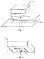
- Figure 1 provides a schematic representation of the relative orientation of the activator means to a substrate upon which it is it to act.
- the activator means 1 has an activator face 2 (the underside of the means as shown) having one or more projections 3 extending from the surface thereof.
- the activator means has two axes, a centerline axis A and a transverse axis B.
- the substrate 4 to be acted upon has a pre-applied adhesive band 5.
- the pre-applied adhesive band 5 has a centerline axis parallel to the centerline axis A of the activator means.
- the relative motion of the substrate to the activator means will be in the direction denoted by the arrow C, along the centerline axis.
- the activator means may also have a reciprocating motion whereby the activator means also moves along the transverse axis B, though such movement will be very small.
- the reciprocating motion is essentially vibrational in nature, the movement along the transverse axis will typically be on the order of nanometers.
- the reciprocating motion is largely responsible for the flow or positioning of the pre-applied adhesive and, where present, the crushing of the microcapsules, the movement along the transverse axis will be on the order of fractions of millimeters to millimeters. In this circumstance, the extent of the movement from one extreme to the other will define the bond width. Consequently, it is preferred that the reciprocation motion be as small as feasible or as needed for the given bond desired.
- reciprocation of the activator means will generally enhance the intermixing of the components of the adhesive or sealant composition; however, reciprocation is particularly important for those activator faces where the projections are aligned in such a manner that gaps exist between the projections when looking down the activator face parallel to the centerline axis.
- the presence of such gaps means that pre-applied adhesive on a substrate in regions corresponding to the gaps will not be acted upon absent a transverse movement of the activator face, preferably transverse movement in each direction that is at least one-half the width of the gap.
- Reciprocation of the activator means is also important, if not critical, where the projections are linear or, if aligned in a linear arrangement, non-linear and parallel with or nearly parallel with the centerline axis. Reciprocation may also be important for use with those linear projections that are wide and perpendicular, or nearly perpendicular, to the centerline axis. In this latter respect, reciprocation will assist with the movement of the activated adhesive or sealant past the ends of the linear projection. This is especially important where the projection is nearly as wide or wider than the band of the pre-applied adhesive or sealant upon which it is acting. Those skilled in the art will readily recognize when such reciprocation is needed in light of the teachings contained herein.
- the activator means comprises, at a minimum an activator body and at least one activator face.
- the activator face may be integral with and form a part of the activator body or, as more clearly shown in Figure 2 , it may be a separate element that is fastened or otherwise bonded to the activator body 6.
- Figure 2 shows an activator face 2 having two linear projections 3 in a herringbone relationship.
- the activator body will also comprise one or more attachment means by which the activator body is attached to a larger apparatus or component thereof for the in-line activation of a pre-applied adhesive on a substrate.
- the activator body may be attached, directly or indirectly, to a robotic arm or means that advances and retracts the activator means to and from the active or operational position in an automated bonding process.
- the activator body may be attached, directly or indirectly, to that part of the frame or superstructure of an automated bonding system and apparatus that is defined as the activation station. In the latter, during use, the activator means would be held substantially stationary while the substrate being acted upon passes the activator face.
- the activator means may also be mounted upon or have associated therewith a manually operated or motorized lift means, with or without associated sensor means, that allows for an adjustment of (a) the distance or gap between the outer surface or peaks of the features or projections on the activator face and the surface of the substrate upon which it is to act and upon which the pre-applied adhesive lies or, as the case may be, (b) the amount of force of such features on the substrate surface when the two are in a touch relationship.
- the activator means may be associated with a reciprocating means which provides reciprocating movement to the activator face which movement is preferably perpendicular to the centerline axis of the activator face.
- the activator face and body may be composed of any number of materials, depending upon the specific nature and use of the activator means, and may be the same or different materials. Suitable materials include metals, ceramics, plastics, and carbides, especially metals like aluminum and anodized aluminum. The specific selection of the material depends, in part, upon the particular end-use application for the activator means and the nature of and sensitivity to or reactivity with the adhesive or sealant material to be acted upon.
- the activator body and the activator face must be made of a material that has excellent heat resistance and heat transfer characteristics so that the requisite heat is present at the surface of the activator face for transfer to the pre-applied adhesive or sealant material without affecting the integrity or life of the activator means.
- the adhesive or sealant composition is a redox curable adhesive or sealant composition
- certain metals especially those containing or based on iron or iron compounds, which may cause adhesive or sealant to bond to the activator face.
- the selection of the material comprising the activator head, especially the activator face should be such that it, either in its virgin state or an aged state, does not adversely interfere with the cure or polymerization of the curable or polymerizable material. In this regard, it is to be understood that interference could be an inhibitory or an acceleration effect on cure.
- composition of the activator face is the physical nature of the adhesive or sealant composition as well as the abrasiveness of the substrate surface upon which it is to act.
- remnants of the microcapsule walls in the case of pre-applied encapsulated adhesives or inorganic fillers of other adhesives may generate excessive wear on the activator face, especially those made of plastic materials.
- the activator face may also have a coating applied thereto.
- These coatings may serve as a barrier to prevent exposure of the adhesive composition to the composition of the activator face and/or have slip or non-bonding characteristics so that the activated adhesive or sealant flows past and through the activator face without bonding or clogging the same.
- the coating may be a release type coating such as a silicone material or polytetrafluoroethylene.
- the coating will be from about 3 to about 6 mils in thickness; however thinner coatings are also suitable.
- the activator face may be a part of the activator means or a separate component that is attached thereto,... mechanically, chemically or otherwise.
- the pattern representing the activator face may be machined into that surface of the activator means which serves as the activator face.
- the pattern representative of the activator face may be formed concurrent with the molding of the activator means.
- the activator face is a separate component that is attached to the activator body, the activator face, including the features to be incorporated thereon or therein, may be machined out of a stock material or made by a molding process.
- the key or critical aspects of the activator means of the present invention are the features on or defining the surface of the activator face. These features are in the form of upwardly extending projections on the surface of the activator face, alone or in combination with one or more recesses or channels that further define the flow path, or a portion thereof, of the adhesive or sealant material through the activator face. Most critical are the projections which engage and lift the pre-applied adhesive or sealant composition from the substrate, directly or indirectly activate or re-activate said adhesive or sealant composition, and direct the flow or movement of the same so as to redeposit the activated or reactivated adhesive or sealant on the substrate.
- the concept of lifting the adhesive or sealant from the substrate refers to the mobilization of the same, though it remains in contact with the substrate surface.
- the addition of channels posterior to the aforementioned projections enables one to then deposit the activated adhesive in a defined pattern and profile.
- the projections serve many functions depending upon their shape, size and orientation on the activator face as well as the nature of the pre-applied adhesive. Foremost, as already noted, the projections must lift and/or push the pre-applied adhesive or sealant composition from the surface of the substrate to which it is applied and, in the case of encapsulated adhesives, help fracture the microcapsules to release the contents thereof.
- the adhesive or sealant composition is a curable or polymerizable composition
- the activator face will also preferably include projections that alter or disrupt the flow path, thereby creating shear or mixing within the curable or polymerizable composition, and/or, if appropriate, participate in the fracturing or crushing of the microcapsules in the case of encapsulated adhesive or sealant compositions.
- the activator face may also include one or more projections that serve to collect and deposit the activated adhesive into a single bead or, depending upon the number and shape of such projections, a plurality of beads.
- the projection may also comprise the forward end of a profile channel, as discussed below.
- the activator face may include one or more projections that divide a single bead into two or more beads.
- many of these projections serve multiple functions at the same time. For example, the projections that lift and collect the pre-applied adhesive or sealant will most likely also create a flow within the mass of material collected, thereby aiding in the mixing of the same.
- any given projection on an activator face are dependent upon the purpose and function that it is to serve.
- the height of the features varies depending upon the adhesive, the desired bead of adhesive arising from the activator means, the line speed, the substrate being acted upon, etc.
- the features of an activator means suitable for use in closing paperboard containers, such as cereal or cookie boxes, will typically have a height of about 18 mils whereas features twice that height and more may be necessary for sealing a corrugated cardboard container.
- these projections are of three overlapping classes: linear projections, diversionary projections and splitters.
- projections may take include, but are not limited to, linear dams and ridges, chevrons, herringbones, "V" shaped or crescent shaped dams or ridges, pyramids, hemispheres, hemispheroids, cylinders, etc.
- a given activator face may have a plurality of identical or like shaped projections, it is preferred that a combination of different shaped projections be employed, particularly where the material to be acted upon is an encapsulated composition.
- Such variation helps promote good microcapsule fracturing, intimate mixing of the components thereof, as well as good bead formation of the activated material.
- those skilled in the art and having the benefit of the teachings herein will readily be able to select the appropriate projections and design the proper orientation of those projections to address their particular needs.
- the projections to be incorporated into or onto the activator face are those that are linear, such as dams and ridges. These linear projections are especially suited for lifting the pre-applied adhesive or sealant from the substrate surface and create flow and mixing of the components as the adhesive passes along the length of the linear projection. When used alone or posterior to other projections, they also serve to collect and direct the flow of the activated adhesive or sealant, preferably creating one or more beads of the activated adhesive. Though the prior art has employed straight edge blades, as noted in Wells et. al.
- the linear edge of the blade is perpendicular to the centerline axis of the adhesive upon which is acts and is angled relative to the surface of the substrate upon which it acts so that the microencapsulated adhesive is crushed and allowed to pass beneath the blade edge.
- fracturing may be poor; however, if one increases the pressure to ensure good fracturing, then the adhesive film arising on the posterior side of the blade is thin, most likely much thinner than the original pre-applied adhesive film upon which the blade acted.
- activation under the prior art is accomplished by a mashing action that, besides forming thin films of adhesive, limits the degree of mixing of the components of the microcapsules. In Wells et.
- the mixing of the components is dictated solely by the flow generated by the compressive forces, a flow that is essentially linear extending outward from and forward of the activator element, e.g., the blade or roller.
- the activator element e.g., the blade or roller.
- the linear projections according to the present invention are not aligned perpendicular to the centerline axis or, if one or more is, their length is less than, preferably substantially less than the width of the band of the pre-applied adhesive or, if as wide or nearly so, the activator means has associated therewith reciprocating means so that the ends of the linear dam at each end of the reciprocation motion are within the pre-applied adhesive band and/or the intended bond line.
- perpendicular linear dams are present in the activators of the present invention, even with reciprocation, they will preferably be very short so as to avoid the build-up of adhesive material on the forward face thereof, which build-up will lead to poor deposits, at least until the amount of build-up exceeds that amount the projection can hold without it spilling past the ends of the projection.
- perpendicular linear projections would be employed with one or more non-linear projections and/or one or more angled linear projections. In essence, their primary function would be to lift the pre-applied adhesive from the substrate surface, not smear the adhesive as with the prior art.
- the linear projections may also be aligned parallel to the centerline axis of the activator means.
- the activator face may have one or more linear projections; however, in these cases the activator means must reciprocate transverse to the centerline axis so that the linear projections can act upon the pre-applied adhesive band. Otherwise, only that adhesive in the line of contact between the linear projection and the pre-applied adhesive will be activated.
- the use of such lateral activation creates a bead of adhesive at the end points of the reciprocation motion of each projection.
- the extent of reciprocation i.e., the size of the movement of the activator face along the transverse axis, should be sufficient to ensure that the full width of the band of pre-applied adhesive is acted upon or, at a minimum, that the desired width of the intended bondline is achieved.
- a single linear projection could be employed, it is oftentimes preferable to employ a plurality of such projections as shown in Figure 19 . This reduces the extent or length of the reciprocation movement needed and helps ensure that more adhesive is being activated, especially in high-speed automated applications.
- a plurality of equally spaced linear projections will create either X+1 beads or 2X beads, where X represents the number of linear projections, depending upon the extent of the reciprocation movement.
- the reciprocation motion be at least such that the furthest movement of a projection in one direction overlaps with the furthest movement of the neighboring projection in the opposite direction, i.e., the reciprocating motion is such that the extreme edges of their paths overlap with those of the neighboring projection. This will.generate X+1 beads and allow for a greater build up of the adhesive beads.
- a shorter movement i.e., where the paths do not overlap or co-terminate, will typically generate 2X beads of lower a profile: though, depending upon the viscosity of the activated adhesive or sealant, the beads may flow and commingle to form a low profile, wide bead.
- the linear projections will be set at an angle relative to the centerline axis of the activator face.
- the specific angle of the linear projections will depend upon a number of factors including the adhesive or sealant to be acted upon, particularly taking into consideration its flow characteristics and viscosity, as well as the number and function of the linear projections, etc. Generally speaking, the angles should not be so low that the width of the adhesive band acted upon is too small to generate an adhesive bead of sufficient volume.
- the angle of the dams or ridges relative to the centerline of the pre-applied adhesive band will be from 20° to 70°, more preferably from 30° to 60°, most preferably from 40° to 50°
- the orientation of the linear projections also plays an important role in the performance and efficacy of the activators of the present invention.
- they may be aligned in any number of different configurations, whether used alone or in combination with other projections.
- the linear projections may be aligned in a herringbone configuration where the forward end of the posterior projection overlaps the trailing end of the forward projection.
- the linear projections may be aligned so as to form a chevron. With this configuration, it is preferred that one or more other projections exist forward of and/or posterior to the gap at the tail end of the chevron.
- one or more raised bands or beads of activated adhesive or sealant may be formed by the selection of certain chevrons in combination with one or more profile channels in the activator face.
- Other alignments/designs for the linear projections include cross-hatch designs, alone or in combination with chevron patterns, as shown in Figures 20 and 21 , respectively; inverted "V"s, as shown in Figure 13 ; and the like.
- the second type of projections incorporated into or protruding from the activator face are those hereinafter referred to as diversionary projections.
- These diversionary projections may be of various shapes including, for example, pyramids, hemispheres, hemispheroids, plateaus, etc. These diversionary projections are especially suited for removing the pre-applied adhesive from the substrate surface and for creating disruptions and shear in the flow of the activated adhesive or sealant materials thereby inducing more mixing thereof. When employed with encapsulated adhesives, these diversionary projections also help in fracturing the microcapsules and the release and intermixing of the encapsulated materials.
- compositions of the latter type are disclosed in US-A-2006073334 .
- the diversionary projections will be used in combination with at least one linear projection, as shown in Figures 4 , 8 and 9 .
- the diversionary projections are primarily responsible for mobilizing the pre-applied adhesive and, as appropriate, fracturing the microcapsules, while the trailing linear projections collect and direct the activated adhesive.
- the resultant adhesive pattern would be in the form of a plurality of low profile beads or ridges of the activated adhesive.
- the lack of staggering and overlap of the paths of the projections of the activator face in Figure 8 results in strips of un-activated adhesive, shown as light colored strips between the darkened activated areas.
- the activation pattern of the activator face of Figure 9 shows that all the pre-applied adhesive has been acted upon as a result of the overlap of the activation paths.
- the diversionary projections be tiered or set in a plurality of rows each of which is off-set relative to the other so that the work areas of the diversionary projections have overlap with one another to ensure that all the pre-applied adhesive is activated.
- any given activator face may employ a plurality of different shaped diversionary projections.
- the height of each diversionary projection will be the same, though such is not required.
- those that are higher will have a greater role in lifting and/or mobilizing the pre-applied adhesive from the substrate as well as fracturing the microcapsules, if present.
- those that are of a lower profile will enhance the shear or alteration of the flow of materials and, if applicable, aid in fracturing the microcapsules as well as mashing and kneading the contents thereof.
- the third class of projections and one that overlaps with the aforementioned classes of projections, especially the linear projections, is characterized as the splitter projections.
- These splitter projections are typically in the shape of crescents, semicircles, and inverted "V"s and are posterior to either of the aforementioned linear and/or diversionary projections. They serve two key functions: to activate any remaining pre-applied adhesive in its path that has yet to be acted upon and, more importantly, to divide the activated adhesive bead or, if none, the activated adhesive film formed in front of it into two or more beads.
- the splitter projections also assist with ensuring fracture of the microcapsules and creating good flow of the adhesive materials for intimate mixing.
- the width of the splitter projection will determine the spacing between the beads created by that projection.
- the short crescent projection of Figure 6 produces two closely arranged parallel beads of activated adhesive as shown in Figure 6(a) .
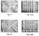
- the wide inverted "V" splitter projection of Figure 11 produces two widely separated parallel beads of the activated adhesive as shown in Figure 11(a) .
- Figures 12 and 12(a) and Figures 13 and 13(a) one may create a larger number of beads by employing a series of cascading splitter projections so that each of the split beads arising from one splitter projection is subsequently split by a trailing splitter projection.
- the combination, number and/or size or length of the projections, especially the linear projections, will also play a role in the efficacy of the activator means. Though more projections and/or longer linear projections, especially, dams or ridges, may increase the efficiency with which the adhesive is lifted from the substrate and increase the degree of mixing of the components before the activated adhesive is redeposited on the substrate, these factors will also affect the dimensions of the activator face, and thus the activator, and, perhaps more importantly, the retention time of the adhesive or sealant in the activator.
- the shortest possible flow path being a straight line which is only achieved with projections that are parallel to the centerline axis and activated by a reciprocation motion.
- said transverse movement in this respect, being due solely to the shapes, size, number and orientation of the projections, there is inherently a displacement of the adhesive from the point at which it was first acted upon by the activator face to a point further along, though not necessarily on, the centerline axis.
- this retention time and, thus, the displacement of the adhesive will depend upon the complexity of the activator face, especially the length of transverse movement of the adhesive in the activator face, and the viscosity of the materials being acted upon.
- the activator face shown in Figure 15 will provide much more intimate mixing of the adhesive or sealant composition than that provided by the similar activator face shown in Figure 10 , the latter will have a much shorter retention time than that of the latter.
- this aspect must be taken into consideration in designing an activator face for a given application.
- a bead displacement of an inch or more is not critical; however, with small boxes, e.g., a box whose size is on the order of a package of cigarettes, such a displacement is not acceptable: though displacements on the order of a half inch or less could be tolerated.
- the flow path along and past the projections must be primed before the activated adhesive or sealant finally passes the end of the last projection and is deposited on the substrate.
- all or a portion of the pre-applied adhesive from the first substrate to pass through the activation station may remain in the activator means until the next substrate with pre-applied adhesive passes through the activation station whereby the newly collected adhesive material 'pushes' the previously retained activated material through the activator means and onto the substrate.
- the adhesive material from the first substrate primes the pump for the next.
- the retention time is substantially longer as it not only reflects the delay due to the transverse motion of the adhesive material within the activator face but also reflects the time interval between activation on one substrate to the next. This happenstance is important in selecting the appropriate pre-applied adhesive composition in order to avoid premature curing in the activator means.
- recesses which may be in the form of pools and/or channels in and among the projections or profile channels that define an exit path or exhaust for the adhesive from the activator face.
- these pools and channels lie below the plane that is defined by the base of the projections and serve as reservoirs and mixing chambers for the adhesive or sealant composition as well as pathways for the flow of the activated adhesive or sealant through and past the projections.
- Such channels if present, are shallow so as to minimize their volume; thus, reducing their impact on the retention time.
- profile channels that define the exit path for the activated adhesive or sealant are desirable, especially when one is endeavoring to create one or more adhesive or sealant beads of defined geometry or profile.
- These profile channels act like funnels, collecting the activated material and allowing it to pass through as one or more defined beads.
- these profile channels will have a chevron or chevron-like shaped forward end that leads into a narrowed pathway extending the remaining length of the activator face.
- the width of the profile channels and their depth, i.e., the height of the sidewalls, will define the bead that arises from or is generated by the activator.
- the depth of the profile channel at the forward end of the channel will be co-planar with the base of the projections; however, as one traverses the length of the profile channel, the depth may increase or decrease depending upon the ultimate bead or beads desired.
- Increasing the depth of the profile channels preferably with a narrowing or tapering of the width of the channels, creates raised or high, narrow beads of the activated adhesive or sealant.
- decreasing the depth of the profile channel preferably with a broadening of the width of the channel, creates low, broad bead of the activated adhesive or sealant.
- the profile channels may also be configured to generate beads of defined profiles or cross-sections.
- the sidewalls may be angled so that they meet at the point of maximum depth, thereby generating a bead of activated material having a triangular profile.
- the sidewalls of the profile channels may be rounded so that a rounded bead is generated. In this latter embodiment, the channel looks much like a lengthwise cross-section of a typical funnel.
- a cross-section of the profile channel at its tail end, perpendicular to the centerline axis, defines the die from which the activated adhesive or sealant is extruded and, therefore, the beads of the activated adhesive or sealant that results from the given activator.
- the viscosity of the activated adhesive will also determine how well and long that profile is maintained following its exit from the activator face. Such may be of little concern in high speed industrial bonding applications since little time exists between the time the substrate exits the activator station and the mating step of the bonding process.
- the viscosity of the activated adhesive in combination with its affinity for the surface of the activator face relative to the substrate surface will also affect the how well the material transverse through and are expelled from the channels.
- the channel may cause a capillary action whereby activated adhesive is retained in the channel until the next charge and/or the combined forces/interactions may cause a drawdown or stringing of the bead along the surface of the substrate.
- the cohesive strength and resistance to flow of the adhesive materials will also affect retention of the same within the channels and the need for repetitive charging for optimal dispensing or discharging of the activated adhesive from the activator face. Again, with proper selection of the adhesive material, one is able to address these concerns, to the extent they are of concern.
- a given activator face may incorporate one or more profile channels defining the exit pathway.
- Figure 16 shows an activator face having a forward semi-circular or crescent dam followed by profile channel whose entry is in the form of a chevron-type dam that also serves as a linear projection that lifts, collects and moves the adhesive or sealant composition.
- Figure 17 depicts an alternate embodiment having two profile channels that are fed by a chevron projection that is preceded by a semi-circular or crescent dam.
- the forward end of the common wall of the profile channels acts as a splitter projection, dividing and feeding the adhesive or sealant composition emanating from the chevron into the two profile channels.
- the forward end of the channel e.g., the chevron or chevron-like entrance or collector
- the forward end of the channel may serve as a linear projection, lifting and mixing the adhesive or sealant
- it is preferred that such profile channels are employed in combination with one or more of the other projections mentioned above, especially one or more linear projections.
- the dimensions of the activator face vary markedly depending upon the volume or rate of application for the pre-applied adhesive to be worked upon; the number, type and complexity of design or pattern of the various features on the activator face; the pattern and profile of the adhesive to exit the activator face; etc.; all of which, in turn, are dependent upon the articles to be activated and the bond or bond area to be formed.
- the width of active region of the activator face i.e., that distance along the transverse axis of the activator face from the outermost projection or portion thereof on one side to the outermost projection or portion thereof on the opposite side of the activator face, will be at least as wide as the band or pattern of pre-applied adhesive or sealant material upon which it is to act.
- the active width of the activator face should be somewhat wider than the band of pre-applied adhesive to be worked upon.
- the length of the activator face should be as short as reasonably possible and practical for the given application.
- the dimension will depend upon the physical properties of the adhesive or sealant, once activated, including the cure speed; the type, length, number and complexity of the features on the work face; the speed of the activation means relative to the substrates upon which it acts; the amount of mixing needed to ensure good cure speed and bond strength; the dimensions and location of the pre-applied adhesive and the intended bondline; etc.
- the length of the transverse flow path i.e., that distance the materials flow transverse to centerline axis, and the volume or space of the flow path, one can reduce the residence or retention time of the adhesive in the activator face and, consequently, the displacement of the adhesive along the centerline axis.
- a reduced residence time will coincide with minimal shift and, in the case of curable and thermoset materials, ensure that the composition has not cured or, since cure will have begun, that the degree of cure is not beyond the point where the adhesive is no longer useful for effectuating the bond.
- the dimensions and design of the activator face are dependent upon a number of interrelated factors and parameters.
- the number, type, shape, orientation or alignment, and pattern of the features, especially the projections, to be incorporated into any given activator face depends largely on the chemistry or physical characteristics of the pre-applied adhesive or sealant material upon which it is to act, the volume of pre-applied adhesive, the substrates to be bonded and the bond or bondline desired.
- the dimensions of the activator face are largely dependent upon the number, type, shape, orientation or alignment, and pattern of the features.
- an activator face in order to activate a given band of pre-applied adhesive of a given chemistry and, in following, one needs adequate space upon which to place the needed features of the activator face to ensure adequate activation and deposition of the activated adhesive or sealant.
- the activator face as defined by the peaks of the projections will be essentially planar; however, as noted above, it is possible that one or more projections may have a lower profile or height than others.
- a series of linear projections may be employed that are stepped so that successive profiles strip the pre-applied adhesive or sealant from the substrate one layer at a time.
- diversionary projections of varying heights to create additional shear and mixing around and under their peaks that may enhance the mashing and kneading of the contents of encapsulated materials.
- the activator face includes one or more profile channels the tops of the sidewalls of said profile channels will also be co-planar or substantially co-planar with the peaks of the projections, or at least the highest of said peaks.
- the activator means and, especially the activator face to be configured to work on non-planar surfaces such as tubular or contoured surfaces.
- the activator face will be contoured so that the contour of its face matches the contour of the substrate upon which it is to act.
- the plane in those instances will be the planar arch defined by the same peaks or bases in their contoured arrangement.
- the activator body must include or have incorporated therein a heating means, such as a resistance wire, ultrasonic horn and the like, or be in a heat transfer relationship with a heating means whereby the necessary heat is transferred through the activator body to the activator face.
- a heating means such as a resistance wire, ultrasonic horn and the like
- the heating means in accordance with the present invention are such that the heat generated is localized at the activator face and/or in the activator body. Since the activator face is fairly small and the sides of the activator face and activator body can be encased or insulated, concern for accidental burning of workers and the like are avoided.
- any potential for impact of the heat on the substrate is limited to the bondline.
- the time of contact between the substrate and the activator face is so small, there is little if any chance that any substantial amount of heat will actually transfer from the one to the other. In essence, all or substantially all heat transfer will be between the activator face and the adhesive material, with little, if any, heat transfer to the substrate.
- the contact time of the adhesive with the activator face is so small, especially in high speed automated applications, there is little if any heat transfer to the adhesive, except, perhaps, to the monolayer of adhesive material at the adhesive/activator face interface.
- the activator means of the present invention may also have incorporated therein or be in a motion transfer relationship with a reciprocating, oscillating or vibration means which imparts movement to the activator face.
- a reciprocating, oscillating or vibration means which imparts movement to the activator face.
- Such means are well known it the art and will comprise, for example, an electric or pneumatic motor with an associated cam.
- the movement to be imparted to the activator face is minimal, preferably one millimeter or less, most preferably less than one-half millimeter. Indeed, for many applications, movement on the order of nanometers is sufficient as the primary goal of such motion is to increase the mixing of the adhesive or sealant composition, including, as appropriate, the mashing and kneading of any microcapsules and their contents.
- the activator means will preferably incorporate or be associated with an adjustment means which allows the operator to set the initial relationship, whether a gap or zero gap, with or without a predetermined compressive force, between the activator face and the substrate surface upon which it is to act.
- the adjustment means will accommodate both manual and automatic adjustments so that the initial or desired height may be set and then the system automatically makes adjustments to accommodate changes in the height or thickness of the substrates upon which it is acting, especially during operation of a fully automated assembly process.
- Suitable adjustment means may be simple in design and construction.
- the means may comprise a tension means e.g., springs, which maintains a constant or near constant force on the activator means so as to maintain pressure contact with the substrate wherein the tension or force is sufficient so that the uppermost surface of the projections maintains contact with the substrate surface even as the activator face lifts the pre-applied adhesive or sealant material from the substrate surface, i.e., the tension is preferably sufficient so that the activator face does not ride above the pre-applied adhesive or the mass of adhesive built up in front of the projections.
- tension means will also allow for an adjustment of the activator means so as to accommodate variations in the thickness of the substrate or sequential substrates as they pass through the activator means.
- the adjustment means may be complex and involve more sophisticated mechanical and/or intricate electronic systems that include a sensing means which identifies variations in the height or thickness of the substrate as it enters the activator means and adjustment means, responsive to the sensing means, that automatically adjusts the height of the activator face to accommodate such variations so as to maintain the desired relationship between the activator face and the substrate surface.
- a sensing means which identifies variations in the height or thickness of the substrate as it enters the activator means
- adjustment means responsive to the sensing means, that automatically adjusts the height of the activator face to accommodate such variations so as to maintain the desired relationship between the activator face and the substrate surface.
- Such systems will accommodate and make adjustments for thickness variations even on the order of microns.
- the gap may be a gap between the activator face and the substrate surface upon which it is acting provided that the gap is less than, preferably no more than one-half, most preferably no more than one-third, the height or thickness of the pre-applied adhesive or sealant on the substrate. Otherwise, the amount of adhesive or sealant activated will likely be insufficient to effectuate a suitable bond or seal.
- the concern with gaps is even more troublesome in the case of encapsulated adhesives and sealants since gaps exceeding about one-half the average particle size of the microcapsules will lead to poor and insufficient fracturing of the encapsulated components and, consequently, insufficient cure and/or adhesive materials to effectuate a suitable bond or seal.
- compositions like those of Schwantes et, al such gaps may result insufficient microcapsule fracture, but Insufficient kneading of the carrier to release or make available sufficient curative to effectuate a suitable bond or seal.
- the activator body be set so that an interference exists between the features of the upper surface of the activator face and the substrate surface upon which it acts.
- the interference will be negligible or only a touch interference: most preferably, the activator means will be set to a depth of from 2.5 to 13 ⁇ m (0.1 to 0.5 mils) below the substrate surface, preferably from 2.5 to 8 ⁇ m (0.1 to 0.3 mils) below the surface.
- a greater interference is desired.
- the activator body will be set so that the upper surface of the features of the activator face will be 0.25 mm (10 mils) or less below the surface of the substrate, preferably 0.13mm (5 mils) or less below the surface of the substrate.
- the interference is not required, it is preferred that the interference be at least 2.5 ⁇ m (0.1 mil), most preferably 8 ⁇ m (0.3 mils), on softer surfaces. Maintaining a low degree of interference minimizes any marring or scoring of the substrate surface while endeavoring to ensure that all of the pre-applied adhesive or sealant is lifted from the substrate surface. This will also help ensure that the activator face will not rise relative to the substrate surface due to a build-up of adhesive or sealant materials on the forward face of the features on the activator face.
- Such a configuration helps maximize the amount of activated adhesive or sealant available to form the bond or seal as well as provide a 'clean' surface for good wet out of the adhesive directly on the substrate surface. Furthermore, this setup minimizes and/or accommodates for any tendency of the activator face to rise relative to the substrate surface during operation, i.e., the happenstance of the activator face hydroplaning on the activated adhesive materials. If a gap exists or the force is insufficient to guard against the activator face rising relative to the substrate surface during operation, a thin film of the pre-applied adhesive or sealant will remain and the activated adhesive or sealant will then bond to that film rather than the substrate surface itself.
- the compressive force between the activator face and the substrate surface so as to avoid or minimize the likelihood of a projection or other feature on the activator face catching on any surface irregularities or imperfections on the substrate surface or of such projections marring the substrate surface as well as to avoid or minimize the likelihood that compressive force will interfere with the substrates, impeding their progression through the activator means or causing the substrates to become misaligned.
- the latter will adversely affect the through-put rate and, potentially, the quality of the product formed; whereas the former, especially in high speed automated operations, may have significant and disastrous consequences including, for example a complete shutdown of the production line in which it is integrated.
- a light touch contact is most preferred.
- the type, chemistry and dimensions of the pre-applied adhesive or sealant to be acted upon are, at least in part, determinative of the selection and positioning or alignment of the projections on the activator face as well as the other features or capabilities of the activator means.
- a pre-applied heat activated/re-activatable thermoset or thermoplastic material has very simple needs relative to the activator face: the presence of a heat source in or in a heat transfer relationship with the activator face and a single linear projection, e.g., one that looks and performs much like a snowplow. If one wanted a plurality of beads for forming the bond, one could employ an inverted "V" shaped projection.
- the chevron configuration will typically have a forward linear or diversionary projection to ensure that the gap defined by the trailing ends of the chevron is activated. Both configurations have the benefit of collecting the activated adhesive or sealant into a larger mass that then exits the activator face.
- the herringbone configuration produces a single raised bead whereas the chevron will produce two beads or, if the gap is small enough, a single, broad bead of the activated adhesive.
- These raised beads provide excellent bonding capabilities and expand the number and variety of applications into to which such pre-applied thermoplastic and thermoset adhesive can be employed. Indeed, raised beads of activated adhesive allow for the use of this technology on non-planar surfaces, on more porous surfaces, and the like.
- encapsulated curable adhesives and sealants present a somewhat more difficult circumstance since the microcapsules must be fractured with high efficiency and the contents thereof intermixed to ensure good and/or efficient cure.
- the former is of utmost concern with encapsulated materials having thick capsule walls and/or small particle size microcapsules.
- the latter is of utmost concern with those compositions, including the aforementioned Schwantes et. al. compositions, wherein mere fracturing of the microcapsules fails to release or make available all of the encapsulated components and/or a sufficient amount of the critical components otherwise necessary to initiate full or even satisfactory cure.
- activator faces for use with curable adhesive and sealant compositions will typically have more complexity, which complexity is most often embodied in the use of a plurality of projections and, most preferably, a combination of different types of such projections. Such variation will help ensure good mobilization of the adhesive or sealant, highly efficient microcapsule fracture and increased shear or mixing of the adhesive or sealant components.
- Such configurations will include a plurality of linear projections or one or more linear projections in combination with one or more diversionary and/or splitter projections.
- the curable compositions are preferably non-heat activated, as also disclosed in Schwantes et. al., certain carrier materials, e.g., low melting waxes and the like, may require elevated temperatures in order to make the curative contained therein accessible to the other constituents of the curable compositions.
- low levels of heat generally 204°C (400°F) or less, preferably from 79°C to 176°C (175°F to 350°F), most preferably from 93°C to 121°C (200°F to 250°F), help the flow of the activated material along the activator face and through and past the projections.
- the actual or preferred temperature will depend upon the adhesive materials used and can be determined by simple trial and error. Though the exact mechanism is not known, it is thought that the heat creates a lower viscosity film at the adhesive/activator face interface: similar in concept to the creation of the water film between the ice and a blade of an ice skate. As in the skate example, because the contact time is so short, the heat transfer is limited to the molecular interface and no heating of the bulk of the adhesive or sealant is seen.
- the activator face could have a plurality of diversionary projections extending across the full width of the band of pre-applied adhesive or sealant, preferably in a staggered orientation, so that the whole of the pre-applied adhesive is acted upon.
- Such an activator face would provide a series of parallel furrows with raised edges, similar to the pattern generated by drawing one's fingers through the top inch or so of sand at the beach.
- Adding reciprocating motion to this activator face will create a ribbon-like pattern of a series of parallel furrows with raised edges or a braided like pattern of the furrows, similar to the patterns shown in Figures 20(a) and 21(a) , respectively, depending upon the spacing and number of rows of the projections.
- the reciprocating motion will also help ensure intimate mixing of the components of the adhesive or sealant compositions should such be needed.
- Activation of the pre-applied adhesive may be accomplished manually using a hand-held device that incorporates the activator body and activator face or, preferably, automatically using automated machinery that holds or incorporates the activator body and activator face. Though there is a large zone of overlap in terms of when each may be used, in the case of curable encapsulated adhesives and sealants, where the cure speed of the activated curable composition is very fast, on the order a second or less, in-line automated activation and assembly will be needed.
- activation of the pre-applied adhesive will be achieved through an automated activator means, either as a stand alone apparatus or machinery that merely activates the pre-applied adhesive or as an in-line activator means that is integrated into a larger industrial assembly or manufacturing apparatus.
- the activator means may be stationary or attached to or part of a robotic arm or like apparatus. In the latter situation, which is especially suited to allow for its use with substrates of non-planar shapes or which have odd shapes whereby an unobstructed path for the activator means is not present as the substrate passes the activator means.
- the activator means is capable of movement from an active mode where it is in-line in the activation workstation and an idle mode where it is off-line and retracted from the actual working site of the activation work station.
- the activator means during the activation step, is not stationary relative to the assembly line apparatus but moves such that the activator passes over or swipes across those sections of the substrate upon which the pre-applied adhesive lies, either in a continuous or discontinuous fashion.
- these apparatus are directly integrated into the assembly line and, for existing lines, can replace those workstations that previously applied a liquid or flowable adhesive and, if present, cured the same or, where appropriate, the heating stations employed with conventional pre-applied heat activated adhesives.
- An especially preferred embodiment of the present invention is that where the substrate to be acted upon is flat or is such that it allows for a stationary activator means to act upon the pre-applied adhesive as the substrate passes through the activator workstation.
- the process is a continuous one whose speed or level of output is only limited by the speed or output of the remaining steps of the assembly or manufacturing process.
- the present invention provides processes where the adhesive application and/or bonding steps are no longer the bottlenecks.
- the present invention is especially suited for use with stock materials, most especially stock packaging materials or blanks, having a pre-applied adhesive or sealant. Due to the planar nature of such stock packaging materials, or at least the flaps or portions thereof upon which the adhesive is pre-applied, these substrates are especially suited for high speed industrial package forming and/or closing operations. Indeed, it is found that automated package formation processes employing stock materials in the form of paperboard blanks may achieve rates of up to 98 m (300 feet) per minute and higher when being activated by an activation means in accordance with the present invention. Even with less than optimal activation, rates of up to 82 m (250 feet) per minute or more can be successfully attained. Such high rates of assembly are in marked contrast to most traditional, automated assembly operations that only achieve rates on the order of 49 m (150 feet) per minute or so.
- a test workstation 10 mimicking an in-line, high speed bonding apparatus, was constructed as shown in Figure 22 .
- This apparatus consisted of four workstations: the Loading Station A, the Activation Station B, the Mating Station C and an End Station (not shown).
- a work sled 11 carried a 5 inch by 8.9cm (3.5 inch) paperboard test card along rail 15 through each workstation.
- test card had a 13 mm (0.5 inch) wide, 10cm (4 inch) long, 0.46 mm (18 mil) thick band of pre-applied encapsulated adhesive made in accordance with the teaching of Schwantes et. al. applied along its centerline beginning at its forward edge and ending approximately 2.5cm (1 inch) from the tail end of the card.
- the adhesive was manually applied to the cards using a coating block.
- the work sled 11 comprises a base 14 and a platform 16. Integrated into the platform 16 were four vacuum ports 18 attached to a vacuum means (not shown) through conduit 19. During testing, at Loading Station A, the card would be centered on the platform 16, adhesive side up, and the vacuum applied to hold the card in place. The vacuum was maintained until the bonded card came to a rest in the End Station. Loading Station A also incorporated a laser sensor means 13 for detecting the height of the surface of the card which communicated with a motorized or, preferably, a hydraulically operated elevator means 22 in the Activation Station B.
- activator means 21 Attached to the elevator means 22 is activator means 21 having an activator face (not shown) attached to the underside of the activator means.
- the elevator means responding to the data supplied by the laser sensor means 13, would adjust the height of the activator means, and thus the activator face, to ensure that the upper surface of the projections on the activator face would come into touch contact with the surface of the paperboard card to which the pre-applied adhesive had been applied.
- mating means 30 includes a work platform 32 and vacuum ports (not shown) for holding the second card to the underside of the platform.
- a piston 33 would lower the work platform 32 until the two cards mated with a pressure of approximately 34 kPa (5 psi). Thereafter the work platform was retracted and the work sled moved on to the End Station.
- the assembled test card structures were then removed from the sled and allowed to set. Subsequently, the assembled test card structures were evaluated for adhesive strength and, for the purpose of this application, microcapsule fracture.
- the latter was determined by solvent extraction on cards subjected to the activator means and others not so subjected in conjunction with gas chromatography of the extractions to determine the amount of liquid monomer released during the activation process versus the total amount of liquid monomer present in the pre-applied adhesive, except here the pre-applied adhesive was inactive, i.e., it lacked the curative ingredient, so that the released liquid would not cure.
- the efficiency of the activator means of the present invention are comparable with, and in most instances better than, those achieved with traditional activator means.
- varying the chemistry and make-up of the encapsulated adhesives will also affect the fracture efficiency.
- the activator means of the present invention have the added benefit of providing the requisite degree of kneading and mashing necessary for effectively employing the encapsulated materials of Schwantes et. al., which show reduced or poor performance absent multiple passes with traditional activator means.
- the activator means of the present invention allow for the generation of beads of activated adhesive, rather than thin films, which greatly expand the applications into which pre-applied adhesive may be employed.
- Activator means in accordance with the present invention were also evaluated on a modified, automated packaging line, one typical for the filling and closing of, for example, a cereal box, with the exception that the apparatus did not employ a hot melt dispensing station.
- Such apparatus are well known in the art and typically comprise a magazine for holding the carton blanks, a conveyor means for moving the carton blank along the production line, a feeding means for placing the carton blanks on the conveyor means, a forming means for squaring the carton blank, an adhesive dispensing means for applying a hot melt adhesive to the end flaps of the carton blank and closure means for closing the flaps and holding them in the close relation to allow the adhesive to cool and seal the carton.
- the apparatus incorporated two activator means in accordance with the present invention, one on each side of the conveyor means at a point subsequent to the squaring and/or filling operation and prior to the closing operation.
- the carton blanks had an encapsulated adhesive pre-applied to the Inner surface of the outer end flaps.
- the encapsulated adhesive was applied via flexographic printing using an anilox roll and a 6.4 mm (0.25 inch) thick flexographic plate which deposited the adhesive in a diamond pattern.
- the apparatus was run as a line speed of about 42 m (150 feet) per minute, though a 82 m (250 feet) per minute speed was also attained - the features on the activator surface acted upon the pre-applied adhesive.
- the closure means closed the end flaps and held the same in the closed position until the formed carton was expelled from the apparatus. The expelled cartons were sealed at each end, demonstrating the effectiveness of the activator means.
Landscapes
- Chemical & Material Sciences (AREA)
- Organic Chemistry (AREA)
- General Engineering & Computer Science (AREA)
- Engineering & Computer Science (AREA)
- Polymers & Plastics (AREA)
- Medicinal Chemistry (AREA)
- Chemical Kinetics & Catalysis (AREA)
- Health & Medical Sciences (AREA)
- Analytical Chemistry (AREA)
- Mechanical Engineering (AREA)
- Adhesives Or Adhesive Processes (AREA)
- Application Of Or Painting With Fluid Materials (AREA)
- Adhesive Tapes (AREA)
- Coating Apparatus (AREA)
- Wrappers (AREA)
Claims (35)
- Verfahren zum Aktivieren eines voraufgetragenen Klebstoffs auf der Fläche eines Substrats, wobei das Verfahren die Schritte des Führens eines Aktivatormittels (1) über den voraufgetragenen Klebstoff auf einer Substratfläche aufweist,
dadurch gekennzeichnet, dass das Aktivatormittel (1) eine Mittellinienachse (A) und, im rechten Winkel dazu, eine Querachse (B) aufweist, dass während der Aktivierung die Mittellinienachse (A) parallel und ausgerichtet zur Richtung der Relativbewegung des Aktivatormittels (1) zu dem Substrat ist und
dass das Aktivatormittel (1) einen Aktivatorkörper (6) aufweist, der mindestens eine Aktivatorstirnseite (2) aufweist, wobei die Aktivatorstirnseite (2) (a) eine Fläche aufweist, wobei die Fläche der Substratfläche, auf die eingewirkt wird, gegenüberliegt, und (b) mehrere Vorsprünge (3) aufweist, die sich von der Substratfläche aus erstrecken, wobei die Vorsprünge (3) in den voraufgetragenen Klebstoff einrücken, wodurch der Klebstoff von der Substratfläche abgehoben wird und der Klebstoff in einem aktivierten Zustand in einem vorbestimmten Muster oder einer vorbestimmten Konfiguration abgeschieden wird,
vorausgesetzt dass, wenn mindestens einer der Vorsprünge (3) ein linearer Vorsprung ist, der im rechten Winkel zu der Mittellinienachse (A) ist, die Länge dieses Vorsprungs wesentlich kleiner als die Breite des voraufgetragenen Klebstoffs ist, auf den eingewirkt werden soll. - Verfahren nach Anspruch 1, wobei der voraufgetragene Klebstoff ein thermoplastischer Klebstoff ist und das Aktivatormittel (1) ferner ein Heizmittel aufweist oder damit in einer Wärmeübertragungsbeziehung ist, wodurch Wärme von dem Heizmittel durch die Aktivatorstirnseite (2) zu dem thermoplastischen Klebstoff übertragen wird.
- Verfahren nach Anspruch 1, wobei der voraufgetragene Klebstoff ein verkapselter Klebstoff ist, wobei die Vorsprünge (3) die Mikrokapseln, welche die Klebstoffkomponenten enthalten, brechen und ausreichenden Fluss innerhalb der Klebstoffmasse erzeugen, um Aktivierung zu bewirken, bevor diese auf dem Substrat abgeschieden wird.
- Vorrichtung zum Durchführen des Verfahrens nach einem vorhergehenden Anspruch, wobei die Vorrichtung das Aktivatormittel (1) aufweist.
- Vorrichtung nach Anspruch 4, wobei, wenn die Fläche der Aktivatorstirnseite (2) in der Richtung ihrer Mittellinie an ihrer Achse betrachtet wird, die Vorsprünge (3) eine Wand zu bilden scheinen, die sich zwischen den zwei Vorsprüngen (3) erstreckt, die sich am weitesten und auf entgegengesetzten Seiten von der Mittellinienachse (A) befinden, wobei die Wand einen oder mehrere Spalte aufweist.
- Aktivatormittel nach Anspruch 5, ferner aufweisend ein sich hin- und herbewegendes Mittel, wobei das sich hin- und herbewegende Mittel die Aktivatorstirnseite (2) längs der Querachse (B) vor- und zurückbewegt.
- Aktivatormittel nach Anspruch 6, wobei das Ausmaß der Bewegung von der Mittellinienachse (A) weg, die der Aktivatorstirnseite (2) von dem sich hin- und herbewegenden Mittel verliehen wird, etwa die Hälfte der Breite des Spaltes in jeder Richtung beträgt.
- Aktivatormittel nach Anspruch 4, wobei die Vorsprünge (3) aus linearen Dämmen und Wülsten, Zickzackleisten, Fischgräten, umgekehrten "V"-förmigen oder sichelförmigen Dämmen oder Wülsten, Pyramiden, Halbkugeln, Halbsphäroiden und Zylindern und Kombinationen davon ausgewählt sind.
- Aktivatormittel nach Anspruch 4, wobei die Vorsprünge (3) in einer gestaffelten Beziehung längs der Mittellinienachse (A) sind, die Mittellinienachse (A) jedoch nicht notwendigerweise schneiden, derart, dass sich mindestens ein Abschnitt eines Vorsprungs mit einem Abschnitt eines anderen Vorsprungs überlappt, wenn in der Richtung der Mittellinienachse (A) betrachtet wird.
- Aktivatormittel nach Anspruch 4, das mindestens einen linearen Vorsprung oder einen Vorsprung, der lineare Erweiterungen hinter einem oder mehreren anderen, im Wesentlichen nicht linearen Vorsprüngen (3) aufweist, aufweist.
- Aktivatormittel nach Anspruch 4, wobei die im Wesentlichen nicht linearen Vorsprünge (3) aus der Gruppe ausgewählt sind, die aus umgekehrten Sicheln, kleinen umgekehrten "V", Halbkugeln, Halbsphäroiden, Pyramiden und Zylindern besteht.
- Aktivatormittel nach Anspruch 4, wobei mindestens einer der Vorsprünge (3) ein linearer Vorsprung oder ein Vorsprung ist, der lineare Erweiterungen oder Arme aufweist.
- Aktivatormittel nach Anspruch 12, wobei der lineare Vorsprung oder die lineare Erweiterung unter einem Winkel in Bezug auf die Mittellinienachse (A) platziert ist, wobei der Winkel etwa 20° bis etwa 70° beträgt.
- Aktivatormittel nach Anspruch 12, wobei der lineare Vorsprung oder die lineare Erweiterung unter einem Winkel in Bezug auf die Mittellinienachse (A) platziert ist, wobei der Winkel etwa 30° bis etwa 60° beträgt.
- Vorrichtung nach Anspruch 4, wobei die Vorsprünge (3) in einer linearen Beziehung parallel zu der Querachse (B) ausgerichtet sind.
- Vorrichtung nach Anspruch 4, wobei die Vorsprünge (3) in mehreren Reihen ausgerichtet sind, jede Reihe parallel zu der Querachse (B).
- Vorrichtung nach Anspruch 16, wobei die Vorsprünge (3) in einer Reihe in Bezug auf die Vorsprünge (3) in der benachbarten Reihe gestaffelt sind.
- Vorrichtung nach Anspruch 4, wobei die Aktivatorstirnseite (2) ferner einen oder mehrere Kanäle hinter den Vorsprüngen (3) beinhaltet.
- Vorrichtung nach Anspruch 4, wobei die Vorsprünge (3) aus der Gruppe ausgewählt sind, die aus linearen Vorsprüngen (3), ablenkenden Vorsprüngen (3) und Teilern und Kombinationen davon besteht.
- Vorrichtung nach Anspruch 4, wobei die Aktivatorstirnseite (2) aus Metall, Kunststoff, Karbid oder Keramik besteht.
- Vorrichtung nach Anspruch 4, wobei die Aktivatorstirnseite (2) aus einem Material besteht, das hitzebeständig ist und gute Wärmeübertragungsfähigkeiten aufweist.
- Vorrichtung nach Anspruch 4, wobei die Fläche der Aktivatorstirnseite (2) einschließlich der Vorsprünge (3) eine Beschichtung darauf aufweist, wobei die Beschichtung gegenüber dem Klebstoffmaterial, das aktiviert werden soll, inert ist.
- Vorrichtung nach Anspruch 22, wobei die Beschichtung aus Polytetrafluorethylen und einem Silikonmaterial ausgewählt ist.
- Vorrichtung nach Anspruch 4, wobei die Aktivatorstirnseite (2) einstückig mit dem Aktivatorkörper (6) ist.
- Vorrichtung nach Anspruch 4, wobei die Aktivatorstirnseite (2) an dem Aktivatorkörper (6) befestigt ist.
- Vorrichtung nach Anspruch 4, ferner Heizmittel aufweisend.
- Vorrichtung nach Anspruch 4, wobei die Aktivatorstirnseite (2) in einer Wärmeübertragungsbeziehung mit einem Heizmittel ist.
- Vorrichtung nach Anspruch 4, ferner aufweisend ein sich hin- und herbewegendes Mittel zum Versehen der Aktivatorstirnseite (2) mit Hin- und Herbewegung.
- Vorrichtung nach Anspruch 4, ferner aufweisend ein Hebemittel zum Einstellen des Abstandes zwischen der Aktivatorstirnseite (2) und einem Substrat, auf das sie einwirken soll.
- Vorrichtung nach Anspruch 29, ferner aufweisend ein Fühlmittel zum Erfassen von Abweichungen der Höhe der Substratfläche, auf welche die Aktivatorstirnseite (2) einwirken soll, in Bezug auf das Platzieren der Aktivatorstirnseite (2), um die Einstellung des Aktivatormittels (1) zu ermöglichen.
- Vorrichtung nach Anspruch 4, wobei die Vorsprünge (3) und Kanäle, sofern vorhanden, gleichzeitig mit der Herstellung der Aktivatorstirnseite (2) in die Aktivatorstirnseite (2) geformt wurden.
- Vorrichtung nach Anspruch 4, wobei die Aktivatorstirnseite (2) aus einem Lagermaterial hergestellt ist, wobei die Vorsprünge (3) und Kanäle, sofern vorhanden, zu Lagermaterial gemahlen wurden.
- Vorrichtung nach Anspruch 4, ferner aufweisend ein sich hin- und herbewegendes Mittel zum Bewirken einer sekundären Bewegung der Aktivatorstirnseite (2) längs der Querachse (B);
wobei, wenn der lineare Vorsprung im Wesentlichen im rechten Winkel zu der Mittellinienachse (A) ist, die Länge des linearen Vorsprungs kleiner ist als die Breite des Musters des voraufgetragenen Klebstoffs auf der Substratfläche und die Bewegung der Aktivatorstirnseite (2) längs der Querachse (B) ausreicht, um zu ermöglichen, dass eine wirksame Menge Klebstoff den linearen Vorsprung passiert, während sich das Aktivatormittel (1) in Bezug auf die Substratfläche längs der Mittellinienachse (A) bewegt; und
wobei, wenn der lineare Vorsprung im Wesentlichen parallel zu der Mittellinienachse (A) ist, die Bewegung der Aktivatorstirnseite (2) längs der Querachse (B) ausreicht, um auf eine wirksame Menge voraufgetragenen Klebstoffs zu wirken, während sich das Aktivatormittel (1) in Bezug auf die Substratfläche längs der Mittellinienachse (A) bewegt, und wobei die Aktivatorstirnseite (2) mehrere lineare Vorsprünge (3) aufweist, die im Wesentlichen parallel zu der Mittellinienachse (A) sind. - Vorrichtung nach Anspruch 4, ferner aufweisend ein sich hin- und herbewegendes Mittel zum Bewirken einer sekundären Bewegung der Aktivatorstirnseite (2) längs der Querachse (B);
wobei, wenn der lineare Vorsprung im Wesentlichen im rechten Winkel zu der Mittellinienachse (A) ist, die Länge des linearen Vorsprungs kleiner ist als die Breite des Musters des voraufgetragenen Klebstoffs auf der Substratfläche und die Bewegung der Aktivatorstirnseite (2) längs der Querachse (B) ausreicht, um zu ermöglichen, dass eine wirksame Menge Klebstoff den linearen Vorsprung passiert, während sich das Aktivatormittel (1) in Bezug auf die Substratfläche längs der Mittellinienachse (A) bewegt; und
wobei, wenn der lineare Vorsprung im Wesentlichen parallel zu der Mittellinienachse (A) ist, die Bewegung der Aktivatorstirnseite (2) längs der Querachse (B) ausreicht, um auf eine wirksame Menge voraufgetragenen Klebstoffs zu wirken, während sich das Aktivatormittel (1) in Bezug auf die Substratfläche längs der Mittellinienachse (A) bewegt, und wobei die Aktivatorstirnseite (2) mehrere lineare Vorsprünge (3) aufweist, die im Wesentlichen im rechten Winkel zu der Mittellinienachse (A) sind, wobei die linearen Vorsprünge (3) kollinear oder gestaffelt längs der Mittellinienachse (A) sind, diese jedoch nicht notwendigerweise schneiden, oder beides sind. - Vorrichtung nach Anspruch 4, ferner aufweisend ein sich hin- und herbewegendes Mittel zum Bewirken einer sekundären Bewegung der Aktivatorstirnseite (2) längs der Querachse (B);
wobei, wenn der lineare Vorsprung im Wesentlichen im rechten Winkel zu der Mittellinienachse (A) ist, die Länge des linearen Vorsprungs kleiner ist als die Breite des Musters des voraufgetragenen Klebstoffs auf der Substratfläche und die Bewegung der Aktivatorstirnseite (2) längs der Querachse (B) ausreicht, um zu ermöglichen, dass eine wirksame Menge Klebstoff den linearen Vorsprung passiert, während sich das Aktivatormittel (1) in Bezug auf die Substratfläche längs der Mittellinienachse (A) bewegt; und
wobei, wenn der lineare Vorsprung im Wesentlichen parallel zu der Mittellinienachse (A) ist, die Bewegung der Aktivatorstirnseite (2) längs der Querachse (B) ausreicht, um auf eine wirksame Menge voraufgetragenen Klebstoffs zu wirken, während sich das Aktivatormittel (1) in Bezug auf die Substratfläche längs der Mittellinienachse (A) bewegt, und wobei die Aktivatorstirnseite (2) mehrere lineare Vorsprünge (3) aufweist, die im Wesentlichen im rechten Winkel zu der Mittellinienachse (A) sind, wobei die linearen Vorsprünge (3) gestaffelt längs der Mittellinienachse (A) sind, diese jedoch nicht notwendigerweise schneiden.
Applications Claiming Priority (3)
| Application Number | Priority Date | Filing Date | Title |
|---|---|---|---|
| US66513405P | 2005-03-25 | 2005-03-25 | |
| US69200805P | 2005-06-17 | 2005-06-17 | |
| PCT/US2006/007043 WO2006104625A2 (en) | 2005-03-25 | 2006-02-28 | Activator means for pre-applied adhesives |
Publications (3)
| Publication Number | Publication Date |
|---|---|
| EP1871594A2 EP1871594A2 (de) | 2008-01-02 |
| EP1871594A4 EP1871594A4 (de) | 2012-05-02 |
| EP1871594B1 true EP1871594B1 (de) | 2016-10-12 |
Family
ID=37053859
Family Applications (3)
| Application Number | Title | Priority Date | Filing Date |
|---|---|---|---|
| EP06736272.3A Expired - Lifetime EP1863634B1 (de) | 2005-03-25 | 2006-02-28 | Mit klebstoff zu befestigende vorratsmaterialien |
| EP06736278.0A Expired - Lifetime EP1861246B1 (de) | 2005-03-25 | 2006-02-28 | Mit klebstoff zu befestigende vorratsverpackungsmaterialien |
| EP06721110.2A Expired - Lifetime EP1871594B1 (de) | 2005-03-25 | 2006-02-28 | Beschleunigungsmittel für voraufgebrachte klebstoffe |
Family Applications Before (2)
| Application Number | Title | Priority Date | Filing Date |
|---|---|---|---|
| EP06736272.3A Expired - Lifetime EP1863634B1 (de) | 2005-03-25 | 2006-02-28 | Mit klebstoff zu befestigende vorratsmaterialien |
| EP06736278.0A Expired - Lifetime EP1861246B1 (de) | 2005-03-25 | 2006-02-28 | Mit klebstoff zu befestigende vorratsverpackungsmaterialien |
Country Status (4)
| Country | Link |
|---|---|
| EP (3) | EP1863634B1 (de) |
| JP (3) | JP4975731B2 (de) |
| CA (3) | CA2602139C (de) |
| WO (3) | WO2006104622A2 (de) |
Families Citing this family (12)
| Publication number | Priority date | Publication date | Assignee | Title |
|---|---|---|---|---|
| EP1863634B1 (de) * | 2005-03-25 | 2017-03-29 | Encapsys, Llc | Mit klebstoff zu befestigende vorratsmaterialien |
| BRPI0812337A2 (pt) | 2007-06-11 | 2015-01-27 | Appleton Paper Inc | Agente de benefício contendo partícula de liberação |
| CA2729101A1 (en) * | 2008-07-21 | 2010-01-28 | Dixie Consumer Products Llc | Paper cup manufacture with microencapsulated adhesive |
| JP2017509729A (ja) * | 2014-01-02 | 2017-04-06 | エメラルド・カラマ・ケミカル・エルエルシーEmerald Kalama Chemical,LLC | 安息香酸エンドキャップを有するポリエステル可塑剤 |
| CN105197344A (zh) * | 2014-06-25 | 2015-12-30 | 艾尔戴克斯国际公司 | 承载结构 |
| CN112480370A (zh) | 2015-03-19 | 2021-03-12 | 泽费罗斯股份有限公司 | 用于高分子材料的酯化酸 |
| CN109563867B (zh) * | 2016-06-17 | 2021-01-01 | 佐治亚-太平洋石膏有限责任公司 | 自密封紧固件、建筑面板、系统和方法 |
| US20180128304A1 (en) * | 2016-11-10 | 2018-05-10 | Nylok Llc | Threaded fastener with hybrid patch |
| AU2020256063B2 (en) | 2019-04-03 | 2022-06-02 | Zephyros, Inc. | Two-part phosphate ester epoxy composition |
| WO2022086726A1 (en) * | 2020-10-23 | 2022-04-28 | Zephyros, Inc. | Dual-cure mechanism polymeric adhesives |
| CN118271914B (zh) * | 2024-03-29 | 2024-11-12 | 江苏飞特尔通信有限公司 | 一种用于ltcc的电镀填孔剂及其制备方法与应用 |
| GB2641789A (en) * | 2024-06-13 | 2025-12-17 | First Fence Ltd | Composition for making patch bolts |
Family Cites Families (99)
| Publication number | Priority date | Publication date | Assignee | Title |
|---|---|---|---|---|
| US2506056A (en) * | 1945-10-06 | 1950-05-02 | Bergstein Samuel | Gastight and gas-filled package and method of making it |
| BE530009A (de) | 1953-06-30 | |||
| US2800457A (en) | 1953-06-30 | 1957-07-23 | Ncr Co | Oil-containing microscopic capsules and method of making them |
| US2730456A (en) | 1953-06-30 | 1956-01-10 | Ncr Co | Manifold record material |
| DE1066687B (de) * | 1958-05-28 | 1900-01-01 | ||
| DE1802886U (de) * | 1959-09-09 | 1959-12-24 | Hesser Ag Maschf | Heisssiegelvorrichtung. |
| US3179143A (en) * | 1960-02-29 | 1965-04-20 | Minnesota Mining & Mfg | Adhesive locked fastening devices |
| US4137194A (en) * | 1961-05-09 | 1979-01-30 | Polaroid Corporation | Capsular products |
| US3489599A (en) | 1966-05-18 | 1970-01-13 | Robert H Krieble | Interfitting parts with nontacky coating of anaerobically polymerizable liquid composition |
| US3516941A (en) | 1966-07-25 | 1970-06-23 | Minnesota Mining & Mfg | Microcapsules and process of making |
| US3547851A (en) | 1968-01-02 | 1970-12-15 | Loctite Corp | Non-flowable anaerobic adhesive |
| JPS5212150B1 (de) | 1968-06-04 | 1977-04-05 | ||
| DE2027737C3 (de) | 1969-07-08 | 1975-11-20 | Ncr Corp., Dayton, Ohio (V.St.A.) | Härtbare Klebstoff- oder Vergußmasse auf Basis von Epoxidharz und ungesättigtem Polyesterharz |
| US3965033A (en) | 1970-07-27 | 1976-06-22 | Fuji Photo Film Co., Ltd. | Process for the production of oil-containing microcapsules |
| US4077926A (en) | 1970-11-12 | 1978-03-07 | Rohm And Haas Company | Pressure sensitive adhesive containing polymerized alkoxyalkyl ester of unsaturated carboxylic acid |
| US4100954A (en) * | 1970-12-04 | 1978-07-18 | Dieter Muller | Dowel or anchoring means |
| US3746068A (en) | 1971-08-27 | 1973-07-17 | Minnesota Mining & Mfg | Fasteners and sealants useful therefor |
| US3886085A (en) | 1971-08-31 | 1975-05-27 | Fuji Photo Film Co Ltd | Process for producing fine oil-containing microcapsules having strong protective shells and microcapsules produced thereby |
| US3814156A (en) | 1971-09-27 | 1974-06-04 | Loctite Corp | Threaded articles with locking or sealing coatings |
| JPS48101058U (de) * | 1972-02-28 | 1973-11-28 | ||
| US4285720A (en) | 1972-03-15 | 1981-08-25 | Stauffer Chemical Company | Encapsulation process and capsules produced thereby |
| US4001140A (en) | 1974-07-10 | 1977-01-04 | Ncr Corporation | Capsule manufacture |
| US4061826A (en) | 1975-01-29 | 1977-12-06 | Minnesota Mining And Manufacturing Company | Flame-retardant pressure-sensitive adhesive composition |
| JPS5833024B2 (ja) * | 1975-05-15 | 1983-07-16 | 松下電工株式会社 | レンゾクトフホウホウ |
| US4093556A (en) | 1975-07-02 | 1978-06-06 | Loctite Corporation | Process for microencapsulation of metallocenes |
| US4081012A (en) | 1976-02-18 | 1978-03-28 | The Oakland Corporation | Thread lock |
| JPS52123561U (de) * | 1976-03-16 | 1977-09-20 | ||
| US4126504A (en) | 1977-01-27 | 1978-11-21 | Pratt & Lambert, Inc. | Adhesive compositions and method employing same |
| US4100103A (en) | 1976-12-30 | 1978-07-11 | Ncr Corporation | Capsule manufacture |
| JPS5425277A (en) | 1977-07-27 | 1979-02-26 | Fuji Photo Film Co Ltd | Method of producing microcapsule |
| US4166152B1 (en) | 1977-08-17 | 1999-05-18 | Minnesota Mining & Mfg | Tacky polymeric microspheres |
| US4283930A (en) * | 1977-12-28 | 1981-08-18 | Aichi Steel Works Limited | Roller-dies-processing method and apparatus |
| JPS54107881A (en) | 1978-02-14 | 1979-08-24 | Fuji Photo Film Co Ltd | Preparation of minute capsule |
| US4830558A (en) | 1978-08-24 | 1989-05-16 | Theodore J. Sweeney & Co. | Adhesively securable fastener |
| US4555206A (en) | 1978-08-24 | 1985-11-26 | Theodore Sweeney & Co. | Adhesively securable fastener |
| US4197346A (en) | 1978-10-10 | 1980-04-08 | Appleton Papers Inc. | Self-contained pressure-sensitive record material and process of preparation |
| DE2905604A1 (de) * | 1979-02-14 | 1980-08-21 | Rissen Gmbh Maschf | Verfahren zum verkleben von papier- und/oder kartonteilen |
| US4252708A (en) | 1979-06-28 | 1981-02-24 | Minnesota Mining And Manufacturing Company | Mechanically activateable one-part liquid resin systems |
| US4536524A (en) | 1981-04-21 | 1985-08-20 | Capsulated Systems, Inc. | Microencapsulated epoxy adhesive system |
| US4768523A (en) | 1981-04-29 | 1988-09-06 | Lifecore Biomedical, Inc. | Hydrogel adhesive |
| US4417028A (en) | 1981-05-11 | 1983-11-22 | Loctite Corporation | Preapplied plastic film adhesive composition |
| US4353325A (en) | 1981-09-28 | 1982-10-12 | Loctite Corporation | Sealant applying apparatus |
| US4444699A (en) | 1982-04-20 | 1984-04-24 | Appleton Papers Inc. | Capsule manufacture |
| US4428982A (en) | 1982-05-17 | 1984-01-31 | The Oakland Corporation | Thread lock |
| IE53781B1 (en) | 1982-09-09 | 1989-02-15 | Loctite Ltd | Composition for forming an a substrate a non-mobile charge curable at a selected later time |
| JPS59159175A (ja) | 1983-03-02 | 1984-09-08 | Konishiroku Photo Ind Co Ltd | 圧力定着性マイクロカプセル型トナ− |
| US4552811A (en) | 1983-07-26 | 1985-11-12 | Appleton Papers Inc. | Capsule manufacture |
| AU561281B2 (en) | 1983-09-14 | 1987-05-07 | Three Bond Co. Ltd. | Acrylic photopolymerised micro-capsules |
| US4610927A (en) | 1983-09-14 | 1986-09-09 | Kureha Kagaku Kogyo Kabushiki Kaisha | Microcapsules containing a hydrophobic, volatile core substance and their production |
| DE3333654A1 (de) | 1983-09-17 | 1985-03-28 | Cassella Ag, 6000 Frankfurt | Verkapselte, in wasser schwerloesliche salze, ihre herstellung und ihre verwendung |
| DE3346601C2 (de) | 1983-12-23 | 1986-06-12 | Feldmühle AG, 4000 Düsseldorf | Mikrokapseln, Verfahren zu ihrer Herstellung und ihre Verwendung in druckempfindlichen kohlefreien Durchschreibepapieren |
| US4601863A (en) | 1984-02-09 | 1986-07-22 | Kanzaki Paper Manufacturing Co., Ltd. | Process for producing powder of microcapsules |
| US4528938A (en) | 1984-05-29 | 1985-07-16 | Arrow-Profile, Inc. | Rotary workpiece treating apparatus |
| US4980410A (en) | 1985-05-10 | 1990-12-25 | E. I. Du Pont De Nemours And Company | Acrylic copolymer composition and adhesive coatings therefrom |
| US4721748A (en) | 1985-08-05 | 1988-01-26 | National Starch And Chemical Corporation | Colloid stabilized latex adhesives |
| US4940852A (en) | 1986-07-16 | 1990-07-10 | Milton P. Chernack | Pressure sensitive adhesive composition |
| US4808639A (en) | 1986-07-16 | 1989-02-28 | Production Previews, Inc. | Liquid curable adhesive composition comprising a polyester resin and a microencapsulated peroxide curing agent |
| US5271881A (en) | 1987-09-28 | 1993-12-21 | Redding Bruce K | Apparatus and method for making microcapsules |
| US4908268A (en) | 1988-03-17 | 1990-03-13 | National Starch And Chemical Corporation | Ethylene vinyl acetate-dioctyl maleate-2-ethylhexyl acrylate interpolymers |
| US5225470A (en) | 1988-08-01 | 1993-07-06 | Monssanto Company | Acrylic hot melt pressure sensitive adhesive compositions |
| US5006582A (en) | 1988-08-01 | 1991-04-09 | E. I. Du Pont De Nemours And Company | Acrylic hot melt pressure sensitive adhesive compositions |
| US4942201A (en) | 1988-08-29 | 1990-07-17 | Illinois Tool Works, Inc. | Adhesive for low temperature applications |
| JP2833111B2 (ja) * | 1989-03-09 | 1998-12-09 | 日立化成工業株式会社 | 回路の接続方法及びそれに用いる接着剤フィルム |
| JPH02258086A (ja) * | 1989-03-30 | 1990-10-18 | Rinrei T-Pu Kk | ストライプ状塗布層の形成方法 |
| DK0471036T4 (da) | 1989-05-04 | 2004-07-19 | Southern Res Inst | Indkapslingsfremgangsmåde |
| US5105823A (en) | 1990-04-05 | 1992-04-21 | Blum Alvin S | Shielded replaceable lancet blade assembly |
| US5140068A (en) | 1990-04-27 | 1992-08-18 | The B. F. Goodrich Company | Epoxy resin systems modified with low viscosity statistical monofunctional reactive polymers |
| US5157077A (en) | 1990-04-27 | 1992-10-20 | The B. F. Goodrich Company | Epoxy resin systems modified with statistical monofunctional reactive polymers |
| US5292835A (en) | 1990-05-16 | 1994-03-08 | Basf Aktiengesellschaft | Microcapsules |
| JPH0517723A (ja) | 1991-07-10 | 1993-01-26 | Three Bond Co Ltd | 接着剤組成物 |
| US6375872B1 (en) * | 1992-11-17 | 2002-04-23 | Moore Business Forms | Microencapsulated adhesive |
| CA2118960A1 (en) | 1993-03-16 | 1994-09-17 | Albert I. Everaerts | Pressure-sensitive adhesives having improved adhesion to acid-rain resistant automotive paints |
| US5827924A (en) | 1993-06-16 | 1998-10-27 | Korea Research Institute Of Chemical Technology | Polymer sealant microencapsulated by polyurethane reaction and its binder solution |
| DE4321205B4 (de) | 1993-06-25 | 2006-06-29 | Basf Ag | Mikrokapseln, Verfahren zu ihrer Herstellung und ihre Verwendung |
| EP0640486B1 (de) * | 1993-08-31 | 1999-03-10 | Shinko Electric Co. Ltd. | Farbdrucker mit Wärmeübergang |
| US5397182A (en) * | 1993-10-13 | 1995-03-14 | Reynolds Consumer Products Inc. | Write-on profile strips for recloseable plastic storage bags |
| US5458929A (en) | 1994-02-15 | 1995-10-17 | The Dow Chemical Company | Cure controlled catalyzed mixtures of epoxy resins and curing agents containing mesogenic moieties, B-staged and cured products therefrom |
| US6531156B1 (en) | 1994-04-15 | 2003-03-11 | Temple University | Aqueous solven encapsulation method, apparatus and microcapsules |
| US5759455A (en) * | 1994-07-08 | 1998-06-02 | Canon Kabushiki Kaisha | Roller-shaped stamper for fabricating optical scales |
| GB9418352D0 (en) | 1994-09-12 | 1994-11-02 | Bp Chem Int Ltd | Plasticizer composition |
| JPH08232940A (ja) * | 1995-02-24 | 1996-09-10 | Toagosei Co Ltd | 水分散型接着剤組成物および該水分散型接着剤組成物を使用したボルトまたはナット |
| US5905099A (en) | 1995-11-06 | 1999-05-18 | Minnesota Mining And Manufacturing Company | Heat-activatable adhesive composition |
| US6407225B1 (en) * | 1995-12-21 | 2002-06-18 | The Dow Chemical Company | Compositions comprising hydroxy-functional polymers |
| US5635546A (en) * | 1996-02-22 | 1997-06-03 | Loctite Corporation | Preapplied silicone threadlocker and sealant |
| JP3257391B2 (ja) | 1996-03-18 | 2002-02-18 | 東洋インキ製造株式会社 | インクジェット記録液 |
| JP3412430B2 (ja) | 1996-10-28 | 2003-06-03 | 株式会社スリーボンド | ねじ部材などに用いられるプレコート型接着剤組成物及びこれを用いたプレコート螺合部材 |
| US5827913A (en) * | 1997-02-05 | 1998-10-27 | H.B. Fuller Licensing & Financing, Inc. | Hot melt adhesive comprising an encapsulated ingredient |
| EP0925946B1 (de) * | 1997-12-26 | 2004-07-07 | Fuji Photo Film Co., Ltd. | Blatttransportmechanismus |
| US6202271B1 (en) * | 1998-03-13 | 2001-03-20 | Matsushita Electric Industrial Co., Ltd. | Method and apparatus for manufacturing expanded mesh sheet and battery using this expanded mesh sheet |
| ES2205812T3 (es) | 1998-04-27 | 2004-05-01 | Essex Specialty Products, Inc. | Metodo para unir un vidrio de ventana a un sustrato utilizando una composicion adhesiva con funcionalidad silano. |
| US20040251175A1 (en) * | 1998-10-30 | 2004-12-16 | Adams Thomas C. | Apparatuses and methods for making glued screen assemblies |
| AU8852601A (en) * | 2000-09-06 | 2002-03-22 | Appleton Paper Inc | In situ microencapsulated adhesive |
| US6573328B2 (en) | 2001-01-03 | 2003-06-03 | Loctite Corporation | Low temperature, fast curing silicone compositions |
| DE10106383A1 (de) * | 2001-02-12 | 2002-08-14 | Schreiner Gmbh & Co Kg | Verfahren zum Aufbringen eines Etiketts auf eine Unterlage |
| US7431975B2 (en) * | 2002-11-29 | 2008-10-07 | Dzs, L.L.C. | Textured composite material |
| US20040142159A1 (en) * | 2003-01-16 | 2004-07-22 | Pallotta Shawn Christopher | Selectively activatable food storage wrap sheet having discreet land areas |
| US20040163768A1 (en) * | 2003-02-22 | 2004-08-26 | Nowicki James W. | Method and means for pre-applying an adhesive to a substrate |
| CA2517607C (en) * | 2003-05-22 | 2012-04-03 | Appleton Papers Inc. | Linerless labels |
| EP1863634B1 (de) * | 2005-03-25 | 2017-03-29 | Encapsys, Llc | Mit klebstoff zu befestigende vorratsmaterialien |
-
2006
- 2006-02-28 EP EP06736272.3A patent/EP1863634B1/de not_active Expired - Lifetime
- 2006-02-28 CA CA2602139A patent/CA2602139C/en not_active Expired - Lifetime
- 2006-02-28 JP JP2008503000A patent/JP4975731B2/ja not_active Expired - Fee Related
- 2006-02-28 JP JP2008502999A patent/JP5090335B2/ja not_active Expired - Fee Related
- 2006-02-28 CA CA2602162A patent/CA2602162C/en not_active Expired - Lifetime
- 2006-02-28 JP JP2008503001A patent/JP5227787B2/ja not_active Expired - Fee Related
- 2006-02-28 EP EP06736278.0A patent/EP1861246B1/de not_active Expired - Lifetime
- 2006-02-28 WO PCT/US2006/006915 patent/WO2006104622A2/en not_active Ceased
- 2006-02-28 WO PCT/US2006/007043 patent/WO2006104625A2/en not_active Ceased
- 2006-02-28 EP EP06721110.2A patent/EP1871594B1/de not_active Expired - Lifetime
- 2006-02-28 WO PCT/US2006/006922 patent/WO2006104623A2/en not_active Ceased
- 2006-02-28 CA CA2602246A patent/CA2602246C/en not_active Expired - Lifetime
Non-Patent Citations (1)
| Title |
|---|
| None * |
Also Published As
| Publication number | Publication date |
|---|---|
| JP2008537754A (ja) | 2008-09-25 |
| WO2006104625A3 (en) | 2007-09-20 |
| EP1863634A4 (de) | 2011-06-29 |
| EP1871594A4 (de) | 2012-05-02 |
| WO2006104625A2 (en) | 2006-10-05 |
| EP1863634B1 (de) | 2017-03-29 |
| JP4975731B2 (ja) | 2012-07-11 |
| CA2602139C (en) | 2013-06-04 |
| JP5227787B2 (ja) | 2013-07-03 |
| EP1871594A2 (de) | 2008-01-02 |
| WO2006104622A3 (en) | 2009-04-16 |
| EP1861246A2 (de) | 2007-12-05 |
| EP1861246B1 (de) | 2017-03-29 |
| JP2008534713A (ja) | 2008-08-28 |
| WO2006104623A3 (en) | 2007-10-04 |
| CA2602162A1 (en) | 2006-10-05 |
| JP2008534390A (ja) | 2008-08-28 |
| EP1863634A2 (de) | 2007-12-12 |
| CA2602162C (en) | 2013-05-14 |
| CA2602246C (en) | 2013-09-10 |
| JP5090335B2 (ja) | 2012-12-05 |
| EP1861246A4 (de) | 2011-06-29 |
| WO2006104622A2 (en) | 2006-10-05 |
| CA2602246A1 (en) | 2006-10-05 |
| CA2602139A1 (en) | 2006-10-05 |
| WO2006104623A2 (en) | 2006-10-05 |
Similar Documents
| Publication | Publication Date | Title |
|---|---|---|
| EP1871594B1 (de) | Beschleunigungsmittel für voraufgebrachte klebstoffe | |
| US9528032B2 (en) | Activator means for pre-applied adhesives | |
| US7632434B2 (en) | Abrasive agglomerate coated raised island articles | |
| EP3322582B1 (de) | 3d-keramikdrucker und verfahren zur verwendung davon | |
| KR101724075B1 (ko) | 불규칙한 표면의 웨지 임프린트 패터닝 | |
| US8256091B2 (en) | Equal sized spherical beads | |
| US8545583B2 (en) | Method of forming a flexible abrasive sheet article | |
| CN1207108C (zh) | 用于将物质传递至目的物表面上的具有多级渐进激活的可选择性激活的三维板材 | |
| EP2572037B1 (de) | Schneid- und/oder Prägewerkzeug und Verfahren zur dessen Herstellung | |
| JP2016128168A (ja) | 高粘着性接着剤を噴射する噴射ディスペンサー及び方法 | |
| US20020061723A1 (en) | Raised island abrasive and process of manufacture | |
| US20090014916A1 (en) | Method and apparatus for producing three-dimensional structure | |
| US5024709A (en) | Contact-free method of forming sift-proof seals | |
| JP5062963B2 (ja) | 傾斜マニホールド及び吐出装置 | |
| EA001987B1 (ru) | Сопло | |
| CA2520301A1 (en) | Method and device for machining composite parts formed from a carrier device and a stamping pad | |
| US20130136870A1 (en) | Droplet Deposition Apparatus and Method for Manufacturing the Same | |
| KR101647119B1 (ko) | 프레스 절단장치를 구비한 사면 포장기 | |
| US5575135A (en) | Paper wrapping process and a machine for performing the paper wrapping process | |
| CN2724960Y (zh) | 双面涂胶封边机 | |
| EP1467844B1 (de) | Schneidwerkzeug umfassend einen schneidkopf mit einer antriebsvorrichtung | |
| US20130155151A1 (en) | Method of manufacturing liquid ejection head | |
| JPH0622520Y2 (ja) | 接着剤塗布装置 | |
| WO1990006219A2 (en) | Device and process for the production of slabs of thermoplastic material | |
| JPH0536282B2 (de) |
Legal Events
| Date | Code | Title | Description |
|---|---|---|---|
| PUAI | Public reference made under article 153(3) epc to a published international application that has entered the european phase |
Free format text: ORIGINAL CODE: 0009012 |
|
| 17P | Request for examination filed |
Effective date: 20071025 |
|
| AK | Designated contracting states |
Kind code of ref document: A2 Designated state(s): AT BE BG CH CY CZ DE DK EE ES FI FR GB GR HU IE IS IT LI LT LU LV MC NL PL PT RO SE SI SK TR |
|
| AX | Request for extension of the european patent |
Extension state: AL BA HR MK YU |
|
| DAX | Request for extension of the european patent (deleted) | ||
| A4 | Supplementary search report drawn up and despatched |
Effective date: 20120404 |
|
| RAP1 | Party data changed (applicant data changed or rights of an application transferred) |
Owner name: APPVION, INC. |
|
| REG | Reference to a national code |
Ref country code: DE Ref legal event code: R079 Ref document number: 602006050549 Country of ref document: DE Free format text: PREVIOUS MAIN CLASS: B32B0003000000 Ipc: B32B0009000000 |
|
| RIC1 | Information provided on ipc code assigned before grant |
Ipc: C08F 212/00 20060101ALI20150908BHEP Ipc: B32B 9/00 20060101AFI20150908BHEP Ipc: B65B 51/14 20060101ALI20150908BHEP Ipc: F16B 39/34 20060101ALI20150908BHEP Ipc: B31B 1/62 20060101ALI20150908BHEP Ipc: C08F 220/00 20060101ALI20150908BHEP Ipc: C08J 3/24 20060101ALI20150908BHEP Ipc: C09J 5/06 20060101ALI20150908BHEP |
|
| 17Q | First examination report despatched |
Effective date: 20151016 |
|
| RAP1 | Party data changed (applicant data changed or rights of an application transferred) |
Owner name: ENCAPSYS, LLC |
|
| GRAP | Despatch of communication of intention to grant a patent |
Free format text: ORIGINAL CODE: EPIDOSNIGR1 |
|
| INTG | Intention to grant announced |
Effective date: 20160413 |
|
| GRAJ | Information related to disapproval of communication of intention to grant by the applicant or resumption of examination proceedings by the epo deleted |
Free format text: ORIGINAL CODE: EPIDOSDIGR1 |
|
| GRAR | Information related to intention to grant a patent recorded |
Free format text: ORIGINAL CODE: EPIDOSNIGR71 |
|
| GRAS | Grant fee paid |
Free format text: ORIGINAL CODE: EPIDOSNIGR3 |
|
| GRAA | (expected) grant |
Free format text: ORIGINAL CODE: 0009210 |
|
| INTC | Intention to grant announced (deleted) | ||
| AK | Designated contracting states |
Kind code of ref document: B1 Designated state(s): AT BE BG CH CY CZ DE DK EE ES FI FR GB GR HU IE IS IT LI LT LU LV MC NL PL PT RO SE SI SK TR |
|
| INTG | Intention to grant announced |
Effective date: 20160902 |
|
| REG | Reference to a national code |
Ref country code: GB Ref legal event code: FG4D |
|
| REG | Reference to a national code |
Ref country code: CH Ref legal event code: EP |
|
| REG | Reference to a national code |
Ref country code: AT Ref legal event code: REF Ref document number: 836123 Country of ref document: AT Kind code of ref document: T Effective date: 20161015 |
|
| REG | Reference to a national code |
Ref country code: IE Ref legal event code: FG4D |
|
| REG | Reference to a national code |
Ref country code: DE Ref legal event code: R096 Ref document number: 602006050549 Country of ref document: DE |
|
| REG | Reference to a national code |
Ref country code: LT Ref legal event code: MG4D |
|
| REG | Reference to a national code |
Ref country code: NL Ref legal event code: MP Effective date: 20161012 |
|
| PG25 | Lapsed in a contracting state [announced via postgrant information from national office to epo] |
Ref country code: LV Free format text: LAPSE BECAUSE OF FAILURE TO SUBMIT A TRANSLATION OF THE DESCRIPTION OR TO PAY THE FEE WITHIN THE PRESCRIBED TIME-LIMIT Effective date: 20161012 |
|
| REG | Reference to a national code |
Ref country code: AT Ref legal event code: MK05 Ref document number: 836123 Country of ref document: AT Kind code of ref document: T Effective date: 20161012 |
|
| PG25 | Lapsed in a contracting state [announced via postgrant information from national office to epo] |
Ref country code: SE Free format text: LAPSE BECAUSE OF FAILURE TO SUBMIT A TRANSLATION OF THE DESCRIPTION OR TO PAY THE FEE WITHIN THE PRESCRIBED TIME-LIMIT Effective date: 20161012 Ref country code: LT Free format text: LAPSE BECAUSE OF FAILURE TO SUBMIT A TRANSLATION OF THE DESCRIPTION OR TO PAY THE FEE WITHIN THE PRESCRIBED TIME-LIMIT Effective date: 20161012 Ref country code: GR Free format text: LAPSE BECAUSE OF FAILURE TO SUBMIT A TRANSLATION OF THE DESCRIPTION OR TO PAY THE FEE WITHIN THE PRESCRIBED TIME-LIMIT Effective date: 20170113 |
|
| PG25 | Lapsed in a contracting state [announced via postgrant information from national office to epo] |
Ref country code: ES Free format text: LAPSE BECAUSE OF FAILURE TO SUBMIT A TRANSLATION OF THE DESCRIPTION OR TO PAY THE FEE WITHIN THE PRESCRIBED TIME-LIMIT Effective date: 20161012 Ref country code: AT Free format text: LAPSE BECAUSE OF FAILURE TO SUBMIT A TRANSLATION OF THE DESCRIPTION OR TO PAY THE FEE WITHIN THE PRESCRIBED TIME-LIMIT Effective date: 20161012 Ref country code: PL Free format text: LAPSE BECAUSE OF FAILURE TO SUBMIT A TRANSLATION OF THE DESCRIPTION OR TO PAY THE FEE WITHIN THE PRESCRIBED TIME-LIMIT Effective date: 20161012 Ref country code: NL Free format text: LAPSE BECAUSE OF FAILURE TO SUBMIT A TRANSLATION OF THE DESCRIPTION OR TO PAY THE FEE WITHIN THE PRESCRIBED TIME-LIMIT Effective date: 20161012 Ref country code: PT Free format text: LAPSE BECAUSE OF FAILURE TO SUBMIT A TRANSLATION OF THE DESCRIPTION OR TO PAY THE FEE WITHIN THE PRESCRIBED TIME-LIMIT Effective date: 20170213 Ref country code: FI Free format text: LAPSE BECAUSE OF FAILURE TO SUBMIT A TRANSLATION OF THE DESCRIPTION OR TO PAY THE FEE WITHIN THE PRESCRIBED TIME-LIMIT Effective date: 20161012 Ref country code: BE Free format text: LAPSE BECAUSE OF FAILURE TO SUBMIT A TRANSLATION OF THE DESCRIPTION OR TO PAY THE FEE WITHIN THE PRESCRIBED TIME-LIMIT Effective date: 20161012 Ref country code: IS Free format text: LAPSE BECAUSE OF FAILURE TO SUBMIT A TRANSLATION OF THE DESCRIPTION OR TO PAY THE FEE WITHIN THE PRESCRIBED TIME-LIMIT Effective date: 20170212 |
|
| REG | Reference to a national code |
Ref country code: DE Ref legal event code: R097 Ref document number: 602006050549 Country of ref document: DE |
|
| PG25 | Lapsed in a contracting state [announced via postgrant information from national office to epo] |
Ref country code: SK Free format text: LAPSE BECAUSE OF FAILURE TO SUBMIT A TRANSLATION OF THE DESCRIPTION OR TO PAY THE FEE WITHIN THE PRESCRIBED TIME-LIMIT Effective date: 20161012 Ref country code: DK Free format text: LAPSE BECAUSE OF FAILURE TO SUBMIT A TRANSLATION OF THE DESCRIPTION OR TO PAY THE FEE WITHIN THE PRESCRIBED TIME-LIMIT Effective date: 20161012 Ref country code: CZ Free format text: LAPSE BECAUSE OF FAILURE TO SUBMIT A TRANSLATION OF THE DESCRIPTION OR TO PAY THE FEE WITHIN THE PRESCRIBED TIME-LIMIT Effective date: 20161012 Ref country code: EE Free format text: LAPSE BECAUSE OF FAILURE TO SUBMIT A TRANSLATION OF THE DESCRIPTION OR TO PAY THE FEE WITHIN THE PRESCRIBED TIME-LIMIT Effective date: 20161012 Ref country code: RO Free format text: LAPSE BECAUSE OF FAILURE TO SUBMIT A TRANSLATION OF THE DESCRIPTION OR TO PAY THE FEE WITHIN THE PRESCRIBED TIME-LIMIT Effective date: 20161012 |
|
| PLBE | No opposition filed within time limit |
Free format text: ORIGINAL CODE: 0009261 |
|
| STAA | Information on the status of an ep patent application or granted ep patent |
Free format text: STATUS: NO OPPOSITION FILED WITHIN TIME LIMIT |
|
| PG25 | Lapsed in a contracting state [announced via postgrant information from national office to epo] |
Ref country code: BG Free format text: LAPSE BECAUSE OF FAILURE TO SUBMIT A TRANSLATION OF THE DESCRIPTION OR TO PAY THE FEE WITHIN THE PRESCRIBED TIME-LIMIT Effective date: 20170112 Ref country code: IT Free format text: LAPSE BECAUSE OF FAILURE TO SUBMIT A TRANSLATION OF THE DESCRIPTION OR TO PAY THE FEE WITHIN THE PRESCRIBED TIME-LIMIT Effective date: 20161012 |
|
| 26N | No opposition filed |
Effective date: 20170713 |
|
| PG25 | Lapsed in a contracting state [announced via postgrant information from national office to epo] |
Ref country code: MC Free format text: LAPSE BECAUSE OF FAILURE TO SUBMIT A TRANSLATION OF THE DESCRIPTION OR TO PAY THE FEE WITHIN THE PRESCRIBED TIME-LIMIT Effective date: 20161012 |
|
| REG | Reference to a national code |
Ref country code: CH Ref legal event code: PL |
|
| PG25 | Lapsed in a contracting state [announced via postgrant information from national office to epo] |
Ref country code: LI Free format text: LAPSE BECAUSE OF NON-PAYMENT OF DUE FEES Effective date: 20170228 Ref country code: CH Free format text: LAPSE BECAUSE OF NON-PAYMENT OF DUE FEES Effective date: 20170228 |
|
| REG | Reference to a national code |
Ref country code: IE Ref legal event code: MM4A |
|
| PG25 | Lapsed in a contracting state [announced via postgrant information from national office to epo] |
Ref country code: SI Free format text: LAPSE BECAUSE OF FAILURE TO SUBMIT A TRANSLATION OF THE DESCRIPTION OR TO PAY THE FEE WITHIN THE PRESCRIBED TIME-LIMIT Effective date: 20161012 |
|
| REG | Reference to a national code |
Ref country code: FR Ref legal event code: ST Effective date: 20171031 |
|
| PG25 | Lapsed in a contracting state [announced via postgrant information from national office to epo] |
Ref country code: LU Free format text: LAPSE BECAUSE OF NON-PAYMENT OF DUE FEES Effective date: 20170228 |
|
| PG25 | Lapsed in a contracting state [announced via postgrant information from national office to epo] |
Ref country code: FR Free format text: LAPSE BECAUSE OF NON-PAYMENT OF DUE FEES Effective date: 20170228 |
|
| PG25 | Lapsed in a contracting state [announced via postgrant information from national office to epo] |
Ref country code: IE Free format text: LAPSE BECAUSE OF NON-PAYMENT OF DUE FEES Effective date: 20170228 |
|
| PG25 | Lapsed in a contracting state [announced via postgrant information from national office to epo] |
Ref country code: HU Free format text: LAPSE BECAUSE OF FAILURE TO SUBMIT A TRANSLATION OF THE DESCRIPTION OR TO PAY THE FEE WITHIN THE PRESCRIBED TIME-LIMIT; INVALID AB INITIO Effective date: 20060228 |
|
| PG25 | Lapsed in a contracting state [announced via postgrant information from national office to epo] |
Ref country code: CY Free format text: LAPSE BECAUSE OF NON-PAYMENT OF DUE FEES Effective date: 20161012 |
|
| PG25 | Lapsed in a contracting state [announced via postgrant information from national office to epo] |
Ref country code: TR Free format text: LAPSE BECAUSE OF FAILURE TO SUBMIT A TRANSLATION OF THE DESCRIPTION OR TO PAY THE FEE WITHIN THE PRESCRIBED TIME-LIMIT Effective date: 20161012 |
|
| PGFP | Annual fee paid to national office [announced via postgrant information from national office to epo] |
Ref country code: DE Payment date: 20240228 Year of fee payment: 19 Ref country code: GB Payment date: 20240227 Year of fee payment: 19 |
|
| REG | Reference to a national code |
Ref country code: DE Ref legal event code: R119 Ref document number: 602006050549 Country of ref document: DE |
|
| GBPC | Gb: european patent ceased through non-payment of renewal fee |
Effective date: 20250228 |
|
| PG25 | Lapsed in a contracting state [announced via postgrant information from national office to epo] |
Ref country code: DE Free format text: LAPSE BECAUSE OF NON-PAYMENT OF DUE FEES Effective date: 20250902 |
|
| PG25 | Lapsed in a contracting state [announced via postgrant information from national office to epo] |
Ref country code: GB Free format text: LAPSE BECAUSE OF NON-PAYMENT OF DUE FEES Effective date: 20250228 |