EP1872968B1 - Gleitstift - Google Patents
Gleitstift Download PDFInfo
- Publication number
- EP1872968B1 EP1872968B1 EP07103775A EP07103775A EP1872968B1 EP 1872968 B1 EP1872968 B1 EP 1872968B1 EP 07103775 A EP07103775 A EP 07103775A EP 07103775 A EP07103775 A EP 07103775A EP 1872968 B1 EP1872968 B1 EP 1872968B1
- Authority
- EP
- European Patent Office
- Prior art keywords
- pen core
- body casing
- guide
- pen
- core slider
- Prior art date
- Legal status (The legal status is an assumption and is not a legal conclusion. Google has not performed a legal analysis and makes no representation as to the accuracy of the status listed.)
- Not-in-force
Links
Images



Classifications
-
- B—PERFORMING OPERATIONS; TRANSPORTING
- B43—WRITING OR DRAWING IMPLEMENTS; BUREAU ACCESSORIES
- B43K—IMPLEMENTS FOR WRITING OR DRAWING
- B43K24/00—Mechanisms for selecting, projecting, retracting or locking writing units
- B43K24/02—Mechanisms for selecting, projecting, retracting or locking writing units for locking a single writing unit in only fully projected or retracted positions
- B43K24/04—Mechanisms for selecting, projecting, retracting or locking writing units for locking a single writing unit in only fully projected or retracted positions operated by means sliding in longitudinally-slotted casings
-
- B—PERFORMING OPERATIONS; TRANSPORTING
- B43—WRITING OR DRAWING IMPLEMENTS; BUREAU ACCESSORIES
- B43K—IMPLEMENTS FOR WRITING OR DRAWING
- B43K23/00—Holders or connectors for writing implements; Means for protecting the writing-points
- B43K23/008—Holders comprising finger grips
-
- B—PERFORMING OPERATIONS; TRANSPORTING
- B43—WRITING OR DRAWING IMPLEMENTS; BUREAU ACCESSORIES
- B43K—IMPLEMENTS FOR WRITING OR DRAWING
- B43K25/00—Attaching writing implements to wearing apparel or objects involving constructional changes of the implements
- B43K25/02—Clips
-
- B—PERFORMING OPERATIONS; TRANSPORTING
- B43—WRITING OR DRAWING IMPLEMENTS; BUREAU ACCESSORIES
- B43K—IMPLEMENTS FOR WRITING OR DRAWING
- B43K3/00—Nib holders
- B43K3/04—Nib holders with retractable nibs
Definitions
- the present invention relates, in general, to a slide pen having a pen core, a pen core slider, and a body casing, in which the pen core is moved in and out by means of the movement of a pen core slider coupled with a pen core held in the body casing.
- a writing implement comprises a pen core and spring, a pen core case, an operating button, and upper and lower cases.
- the operating button located at an upper portion of the writing implement, is pressed to protrude the pen core.
- the operating button is again pressed to retract the pen core. Thereby, the writing implement enters a portable state.
- This operating button is usually adapted to operate a lock and gear to protrude or retract the pen core.
- lock-type writing implements include four or five constituent pieces, such as the pen core case, the operating button, the upper and lower cases, and so on, that is, they have many parts and a complicated structure, so that the production cost thereof is high, and assembly is difficult.
- US 4, 963, 048 describes a writing instrument with note paper disclosed which includes a retractable writing instrument carrier and a paper storage chamber from which paper may be dispensed through a dispensing slot formed along a substantial portion of a barrel of the device.
- the carrier includes a reservoir of writing medium and a writing point.
- a thumb operator provides for positioning of the carrier in a writing or retracted position.
- the carrier also may move axially along a slot to position a spare paper roll in a dispensing position as paper roll.
- an object of the present invention is to provide a slide pen having a pen core, a pen core slider holding and coupling the pen core, and a body casing holding the pen core slider, wherein the pen core is moved in and out by sliding the pen core slider, with the goal of providing a writing implement having a simple structure and easy assembly.
- a slide pen which includes (a) a pen core having a nib, (b) a tubular pen core slider having an open front (lower) end, a pen core coupler, and guide ridges formed in an back (upper) portion thereof, so as to allow the nib of the pen core to protrude through the lower end thereof and to allow the pen core to be held and coupled therein, and (c) a body casing having a tubular upper portion formed with a guide slot to allow the guide ridges of the pen core slider to axially move and be fixed, a tubular intermediate portion of which is partially open such that the pen core slider is held inside so as to allow the outer circumference of the pen core slider to be exposed outside, and a conical lower portion having an open lower end so as to allow the nib of the pen core to be moved in and out.
- the pen core slider when the guide ridges of the pen core slider axially move in the guide slot of the upper portion of the body casing, the pen core slider can slide in the body casing, and the nib of the pen core coupled to the pen core coupler of the pen core slider can move in and out through the lower end of the body casing .
- the casing comprises a longitudinal opening for inserting the pen core and the pen core slider.
- the guide slot of the upper portion of the body casing may communicate with one end of the intermediate portion of the body casing, because the guide ridges of the pen core slider are adapted to pass through the guide slot when the pen core slider coupled with the pen core is inserted into the body casing, and thereby the pen core slider coupled with the pen core can be assembled to the body casing.
- the guide ridges may include a circular guide ridge having a circular shape in a vertical section and a quadrangular guide ridge having a quadrangular shape in a horizontal section and extending upwards from the circular guide ridge
- the guide slot corresponding to the guide ridges may include a first passage slot that communicates with the open intermediate portion of the body casing to allow the guide ridges of the pen core slider to pass therethrough first when the pen core slider is held in the body casing, a pair of circular slots that communicates with the first passage slot and is formed up and down to be able to clamp the circular guide ridge of the guide ridges, a second passage slot that is formed between the paired circular slots and causes elastic deformation when the elliptical guide ridge passes therethrough, and a linear slot that communicates with the upper one of the paired circular slots and allows the quadrangular guide ridge of the guide ridges to pass therethrough.
- the guide slot corresponding to the guide ridges may include a pair of elliptical slots.
- the slide pen may further include a sheath that encloses the outer circumference of the pen core slider which is exposed to the open intermediate portion of the body casing when the pen core slider is held in the body casing.
- the sheath may have a length equal to or shorter than that of the open intermediate portion of the body casing, and the movement distance of the sheath may be shorter than the distance that the guide ridges of the pen core slider move in the guide slot of the body casing.
- the pen core slider cannot be assembled with the body casing. Further, if the difference between the length of the sheath and the length of the open intermediate portion of the body casing is smaller than the distance that the guide ridges of the pen core slider move in the guide slot, the movement distance of the pen core slider is insufficient, so that the nib of the pen core cannot be protruded far enough. That is, the sheath is shorter than the open intermediate portion of the body casing, and the difference in length between the sheath and the open intermediate portion of the body casing must be greater than the distance that the guide ridges of the pen core slider move in the guide slot of the body casing.
- the length of the sheath may be shorter than that of the open intermediate portion of the body casing, and the movement distance of the sheath may be equal to the distance that the guide ridges of the pen core slider move in the guide slot of the body casing. Thereby, the pen core slider smoothly slides and the nib of the pen core can protrude sufficiently.
- the pen core slider may have the shape of a tube that is partially open so as not to be exposed when coupled to the body casing, and the pen core coupler of the pen core slider may include a pair of opposite flat plates formed at an inner portion of the pen core slider, and the pen core may be coupled between the pair of flat plates.
- the pen core slider may further include a clip, and the clip may be integrally formed with the guide ridges.
- the slide pen may include the sheath as described above, and the sheath may be formed with an embossed portion at a grip portion when the nib of the pen core is moved out, and the body casing in connection with the sheath may be formed with an embossed portion at a grip portion when the nib of the pen core is moved out.
- the embossed portions serving as the grip portions of the sheath and the body casing may be symmetrical with respect to each other.
- the pen core slider and the body casing generally have a circular shape in a transverse section, but it does not matter if they have a quadrangular shape, a hexagonal shape, an octagonal shape, or the like. If the pen core slider and the body casing have any one of the quadrangular, hexagonal, and octagonal shapes in a transverse section, the sheath of the pen core slider has a planar shape, or a quadrangular, hexagonal, or octagonal shape in a transverse section (and, if the pen core slider and the body casing have a circular shape in a transverse section, the sheath of the pen core slider will have a cross section in a "C" shape).
- the pen core slider and the intermediate portion of the body casing, which are open will have the cross section of a quadrangular, hexagonal, or octagonal shape, when the pen core slider and the body casing have any one of the quadrangular, hexagonal, and octagonal shapes in a transverse section (and, if the pen core slider and the body casing have a circular shape in a transverse section, the pen core slider and the intermediate portion of the body casing, which are open, will have a cross section in a "C" shape).
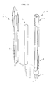
- FIG. 1 is an exploded perspective view illustrating a slide pen according to an embodiment of the present invention.
- the slide pen is comprised of a pen core 1, a pen core slider 20 holding the pen core 1 and removably coupled with the pen core, and a body casing 10 removably holding the pen core slider 20.
- the body casing 10 has an intermediate portion that is partially open. Similarly, the pen core slider 20 is partially open in a longitudinal direction.
- the pen core 1 is coupled to the pen core slider 20, and then the pen core slider 20 having the pen core 1 is assembled into the body casing 10. As a result, the slide pen of the present invention is obtained.
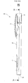
- FIGS. 2A and 2B are a perspective view and side view, respectively, of the pen core slider 20 of FIG. 1
- FIGS. 3A and 3B are a perspective view and side view, respectively, of the body casing 10 of FIG. 1 .
- the pen core slider 20 takes the shape of a cylinder, the circumference of which is partially open from top to bottom, and includes a clip 21, a pen core support 22, a pen core holder 23, a pen core coupler 24, a sheath 26, and guide ridges 28 and 29.
- the clip 21 serves to attach the slide pen to paper or the hem of clothing, as in ordinary writing implements.
- the head 25 is formed at an upper end of the pen core slider 20. Especially, the head 25 is integrally formed with the guide ridges 28 and 29, to be described below, to which the clip 21 is connected. In this manner, the head 25 serves to provide places at which the guide ridges 28 and 29 can be integrally formed.
- the guide ridges 28 and 29 are integrally connected with the clip 21 and the head 25.
- the guide ridges 28 and 29 are constructed such that a guide ridge 28 having an elliptical shape in a vertical section is integrated with a guide ridge 29 that has a quadrangular shape in a horizontal section and extends upwards from the guide ridge 28. Because the elliptical guide ridge 28 and the quadrangular guide ridge 29 are integrally formed, the guide ridges 28 and 29 can be regarded as having a microphone shape on the whole.
- the quadrangular guide ridge 29 has a trapezoidal shape in a vertical section, where the thickness is reduced in an upward direction so as to allow the guide ridges 28 and 29 to smoothly move in a guide slot, to be described below, of the body casing 10.
- the pen core holder 23 refers to the inside of the pen core slider 20, a part of which is open in a vertical direction.
- the pen core coupler 24 is constituted of a pair of flat plates 24', which are integrally formed at an upper inner portion of the pen core slider 20.
- the pen core 1 is held in the pen core holder 23, and has an upper portion interposed and connected between the pair of flat plates 24'.
- the pen core support 22 has a "C" shaped step, which is integrally formed inside the lower end of the pen core slider 20, and cooperates with a protrusion provided on the pen core 1, as illustrated in FIG. 1 .
- the pen core support 22 is not an essential component of the slide pen.
- the pen core slider 20 is also provided with the sheath 26 on an outer circumference thereof.
- the sheath 26 is adapted to enclose the outer circumference of the pen core slider 20, which is exposed to the open intermediate portion of the body casing when the pen core slider 20 is held in the body casing 10.
- the sheath 26 should have a length equal to or shorter than that of the open intermediate portion of the body casing 10. The difference between the length of the sheath 26 and the length of the open intermediate portion of the body casing 10 should be equal to or greater than the distance that the guide ridges 28 and 29 of the pen core slider 20 move in the guide slot G of the body casing 10.
- the length of the open intermediate portion of the body casing 10 should be longer than 1 cm plus the length of the sheath.
- the pen core slider 20 cannot be assembled to the body casing 10. Further, if the difference between the length of the sheath 26 and the length of the open intermediate portion of the body casing 10 is smaller than the distance that the guide ridges 28 and 29 of the pen core slider 20 move in the guide slot G, the movement distance of the pen core slider 20 is insufficient, so that the nib of the pen core 1 cannot be protruded.
- the length of the sheath 26 is shorter than that of the open intermediate portion of the body casing 10, and the difference between the length of the sheath 26 and the length of the open intermediate portion of the body casing 10 is equal to the distance that the guide ridges 28 and 29 of the pen core slider 20 move in the guide slot G of the body casing 10.
- the pen core slider 20 can be adapted to move from side to side, or the nib of the pen core 1 can be adapted to properly protrude.
- the upper and lower ends of the sheath 26 are preferably formed to come into contact with upper and lower ends of the open intermediate portion of the body casing 10, respectively. Further, when the nib of the pen core 1 is protruded for writing, a grip portion of the sheath 26 is preferably formed with an embossed portion A to correspond to an embossed portion B of a grip portion of the body casing 10.
- the sheath 26 is preferably formed with a plurality of convex noses 27 having the same shape at regular intervals on opposite lateral ends thereof.
- the noses 27 are brought into contact with opposite lateral ends of the open intermediate portion of the body casing 10. Thereby, during a writing operation, the noses 27 increase frictional force to prevent the pen core 1 from being moved back. On the contrary, during a sliding operation after the writing operation, the noses 27 minimize surface contact and thus the generation of frictional force, thereby guaranteeing smooth sliding.
- the body casing 10 includes a tubular upper portion 11, the guide slot G formed at the upper portion 11, the partially open intermediate portion 13, and a conical lower portion 14 having a tip 15 open to allow the nib of the pen core 1 to move in and out.
- the conical lower portion 14 having the open tip 15 is typically adapted to be removably coupled to the body casing 10.
- Upper and lower ends of the tubular upper portion 11 of the body casing 10 are provided with a head entrance 16 through which the head 25 of the pen core slider 20 enters or exits when the pen core slider 20 assembled with the pen core 1 is held in the body casing 10, and a pen core entrance 17 through which the pen core 1 assembled to the pen core slider 20 enters or exits.
- the guide slot G of the body casing 10 includes a first passage slot G1 that the guide ridges 28 and 29 of the pen core slider 20 pass through first when the pen core slider 20 is held in the body casing 10, and that communicates with the open intermediate portion 13 of the body casing 10, a pair of elliptical slots G2 that communicates with the first passage slot and is formed up and down to be able to clamp the elliptical guide ridge 28 of the guide ridges 28 and 29, a second passage slot G3 that is formed between the paired elliptical slots G2 and causes elastic deformation when the elliptical guide ridge 28 passes therethrough, and a linear slot G4 that communicates with the upper one of the paired elliptical slots G2 and allows the quadrangular guide ridge 29 of the guide ridges 28 and 29 to pass therethrough.
- a first passage slot G1 that the guide ridges 28 and 29 of the pen core slider 20 pass through first when the pen core slider 20 is held in the body casing 10, and that communicates
- the guide ridges 28 and 29 of the pen core slider 20 move along the guide slot G of the body casing 10, and thus the nib of the pen core 1 moves in and out.
- the nib of the pen core 1 is in a retracted state.
- the nib of the pen core 1 is in a protruded state.
- FIG. 4 is a perspective view illustrating the state where the pen core slider 20 assembled with the pen core 1 is held in the body casing 10, and then the nib of the pen core 1 is in a protruding state.
- FIG. 5 illustrates how the guide ridges 28 and 29 of the pen core slider 20 move in the guide slot G of the body casing 10 when the nib of the pen core 1 moves in and out.
- each dotted line indicates the guide ridges 28 and 29 of the pen core slider 20.
- the user writes while grasping the grip portion A of the sheath 26 of the pen core slider 20 and the grip portion B of the body casing 10 with the forefinger, middle finger and thumb.
- the forefinger and thumb press the pen core slider 20 and body casing 10, respectively, so that the nib of the pen core 1 is more strongly fixed in a protruding state.
- FIG. 6 illustrates a pen core slider 20 of a slide pen according to another embodiment of the present invention, wherein FIG. 6A is a perspective view of the pen core slider 20, FIG. 6B is a side view of the pen core slider 20, and FIG. 6C is a sectional view taken along line A-A in FIG. 6B .
- the pen core slider 20 illustrated in FIG. 6 has the shape of a cylinder, unlike the above-described embodiment having the open intermediate portion ( FIGS. 1 and 2 ), and includes a pen core coupler 24 formed with a circular step on the inner circumference of the upper portion of the pen core slider. Further, the pen core slider 20 illustrated in FIG. 6 is not provided with a pen core support 22, unlike the above-described embodiment having the open intermediate portion.
- a pen core 1 is coupled to the pen core coupler 24 provided at the upper portion of the pen core slider 20, and is then held in a body casing 10.
- any construction will do as long as it is sufficient to withstand the force applied to the pen core 1 coupled to the pen core coupler 24 during a writing operation.
- the slide pen of the present invention is generally comprised of a pen core, a pen core slider, and a body casing, so that it can provide a simple construction as well as easy assembly and operation.
- the slide pen provides an easy production process, and thus can save production cost.
Landscapes
- Mechanical Pencils And Projecting And Retracting Systems Therefor, And Multi-System Writing Instruments (AREA)
- Temperature-Responsive Valves (AREA)
- Pens And Brushes (AREA)
Claims (9)
- Gleitstift, der umfässt:einen Stiftkern (1) mit einer Spitze;einen rohrförmigen Stiftkerngleiter (20) mit einem offenen vorderen Ende, einem Stiftkernkoppier (24) und Führungsstegen (28, 29), die an einem hinteren Abschnitt hiervon ausgebildet sind, um der Spitze des Stiftkerns (1) zu ermöglichen, durch das offene Ende des Stiftkerngleiters (20) vorzustehen, und um zu ermöglichen, dass der Stiftkern (1) gehalten und darin gekoppelt wird; undein Körpergehäuse (10) mit einem rohrförmigen hinteren Abschnitt, der mit einem Führungsschlitz ausgebildet ist, um zu ermöglichen, dass sich die Führungsstege (28, 29) des Stiftkerngleiters (20) axial bewegen und befestigt werden, einem rohrförmigen Zwischenabschnitt, der teilweise offen ist, so dass der Stiftkerngleiter (20) darin gehalten wird, um zu ermöglichen, dass der äußere Umfang des Stiftkerngleiters (20) nach außen freiliegt, und einem konischen vorderen Abschnitt (14), der ein offenes vorderes Ende besitzt, um zu ermöglichen, dass die Spitze des Stiftkerns (1) einwärts und auswärts bewegt wird,wobei dann, wenn sich die Führungsstegen (28, 29) des Stiftkerngleiters (20) in dem Führungsschlitz des hinteren Abschnitts des Körpergehäuses (10) axial bewegen, der Stiftkerngleiter (20) im Körpergehäuse (10) gleitet und die Spitze des Stiftkerns (10), die mit dem Stiftkemkoppler (24) des Stiftkerngleiters (20) gekoppelt ist, sich durch das vordere Ende des Körpergehäuses (10) einwärts und auswärts bewegt,dadurch gekennzeichnet, dass die Teilöffnung in dem rohrförmigen Zwischenabschnitt des Körpergehäuses eine longitudinale Öffnung ist, um den Stiftkern (1) und den Stiftkerngleiter (20) einzusetzen.
- Gleitstift nach Anspruch 1, wobei der Führungsschlitz des oberen Abschnitts des Körpergehäuses (10) mit einem Ende des Zwischenabschnitts des Körpergehäuses (10) in Verbindung steht, um zu ermöglichen, dass die Führungsstege (28, 29) des Stiftkerngleiters (20) sich hindurchbewegen, und um dadurch zu ermöglichen, dass der Stiftkerngleiter (20), der mit dem Stiftkern (1) gekoppelt ist, am Körpergehäuse (10) montiert wird.
- Gleitstift nach Anspruch 1 oder 2, wobei:die Führungsstege (28, 29) einen kreisförmigen Führungssteg (28) mit einer Kreisform in einem vertikalen Querschnitt und einen viereckigen Führungssteg (29) mit einer Viereckform in einem horizontalen Querschnitt, der sich von dem kreisförmigen Führungssteg (28) nach oben erstreckt, besitzen; undder Führungsschlitz, der den Führungsstegen (28, 29) entspricht, einen ersten Durchgangsschlitz, der mit dem offenen Zwischenabschnitt des Körpergehäuses (10) in Verbindung steht, um zu ermöglichen, dass sich die Führungsstege (28, 29) des Stiftkerngleiters (20) erst dann hindurchbewegen, wenn der Stiftkerngleiter (20) in dem Körpergehäuse (10) gehalten wird, ein Paar kreisförmiger Schlitze, die mit dem ersten Durchgangsschlitz in Verbindung steht und oben bzw. unten gebildet sind, um den kreisförmigen Führungssteg (28) der Führungsstege halten zu können, einen zweiten Durchgangsschlitz, der zwischen dem Paar kreisförmiger Schlitze ausgebildet ist und eine elastische Verformung hervorruft, wenn sich der kreisförmige Führungssteg (28) hindurch bewegt, und einen geradlinigen Schlitz, der mit dem oberen Schlitz des Paars kreisförmiger Schlitze in Verbindung steht und ermöglicht, dass der viereckige Führungssteg (29) der Führungsstege sich hindurch bewegt, umfasst.
- Gleitstift nach Anspruch 3, wobei die Führungsstege (28, 29) einen elliptischen Führungssteg (28) mit einer elliptischen Form in einem vertikalen Querschnitt enthalten und der Führungsschlitz, der den Führungsstegen entspricht, ein Paar elliptischer Schlitze enthält.
- Gleitstift nach einem der Ansprüche 1-4, der ferner eine Hülse (26) umfasst, die einen äußeren Umfang des Stiftkerngleiters (20) umschließt, die zu dem offenen Zwischenabschnitt des Körpergehäuses (10) freiliegt, wenn der Stiftkerngleiter (20) in dem Körpergehäuse (10) gehalten wird, und eine Länge besitzt, die gleich oder kleiner als jene des offenen Zwischenabschnitts des Körpergehäuses (10) ist, wobei eine Bewegungsstrecke der Hülse (26) kürzer ist als eine Strecke, über die sich die Führungsstege (28, 29) des Stiftkerngleiters (20) in dem Führungsschlitz des Körpergehäuses (10) bewegen.
- Gleitstift nach Anspruch 5, wobei die Länge der Hülse (26) kürzer ist als der offene Zwischenabschnitt des Körpergehäuses (10) und die Bewegungsstrecke der Hülse (26) gleich der Strecke ist, über die sich die Führungsstege (28, 29) des Stiftkerngleiters (20) in dem Führungsschlitz des Körpergehäuses (10) bewegen.
- Gleitstift nach einem der Ansprüche 1-6, wobei der Stiftkerngleiter (20) die Form eines Rohrs hat, das teilweise geöffnet ist, um nicht freizuliegen, wenn er mit dem Körpergehäuse (10) gekoppelt ist, wobei der Stiftkernkoppler (24) des Stiftkerngleiters (20) ein Paar gegenüberliegender flacher Platten (24') aufweist, die an einem inneren Abschnitt des Stiftkerngleiters (20) ausgebildet sind, und der Stiftkern (1) zwischen dem Paar flacher Platten (24') gekoppelt ist.
- Gleitstift nach einem der Ansprüche 1-7, wobei der Stiftkerngleiter (20) ferner eine Klammer (21) aufweist und die Klammer (21) und die Führungsstege (28, 29) einteilig ausgebildet sind.
- Gleitstift nach einem der Ansprüche 5-8, wobei dann, wenn die Spitze des Stiftkerns (1) auswärts bewegt worden ist, geprägte Abschnitte, die als Greifabschnitte der Hülse (26) dienen, und das Körpergehäuse (10) relativ zueinander symmetrisch sind.
Applications Claiming Priority (1)
| Application Number | Priority Date | Filing Date | Title |
|---|---|---|---|
| KR20060060460 | 2006-06-30 |
Publications (2)
| Publication Number | Publication Date |
|---|---|
| EP1872968A1 EP1872968A1 (de) | 2008-01-02 |
| EP1872968B1 true EP1872968B1 (de) | 2010-09-01 |
Family
ID=38543746
Family Applications (1)
| Application Number | Title | Priority Date | Filing Date |
|---|---|---|---|
| EP07103775A Not-in-force EP1872968B1 (de) | 2006-06-30 | 2007-03-08 | Gleitstift |
Country Status (9)
| Country | Link |
|---|---|
| US (1) | US7677824B2 (de) |
| EP (1) | EP1872968B1 (de) |
| JP (1) | JP4500323B2 (de) |
| KR (1) | KR100755881B1 (de) |
| CN (1) | CN100473540C (de) |
| AT (1) | ATE479558T1 (de) |
| DE (1) | DE602007008792D1 (de) |
| MY (1) | MY144790A (de) |
| WO (1) | WO2008002003A1 (de) |
Families Citing this family (9)
| Publication number | Priority date | Publication date | Assignee | Title |
|---|---|---|---|---|
| WO2010010825A1 (ja) * | 2008-07-24 | 2010-01-28 | 株式会社壽 | ノック式筆記具 |
| TW201414620A (zh) * | 2012-10-12 | 2014-04-16 | Xin Zhuan Invest Co Ltd | 以滑動方式啟閉筆蓋之筆 |
| CN102848803B (zh) * | 2012-10-15 | 2014-08-20 | 青岛点石文具用品有限公司 | 滑动式笔 |
| CN103395316A (zh) * | 2013-04-08 | 2013-11-20 | 余成鹏 | 一种环保拔笔 |
| WO2014207869A1 (ja) * | 2013-06-27 | 2014-12-31 | ジャプロ株式会社 | スライド式メークアップ用具 |
| KR101538275B1 (ko) * | 2014-11-18 | 2015-07-22 | 천광주 | 출몰식 필기구의 푸쉬 로크장치 |
| KR101712539B1 (ko) | 2015-03-12 | 2017-03-06 | 주식회사 모리스 | 슬라이드식 필기구 |
| CN112230063A (zh) * | 2020-10-10 | 2021-01-15 | 广东电网有限责任公司广州供电局 | 一种测量表笔 |
| US12697835B2 (en) * | 2024-06-14 | 2026-08-04 | Sam Van Vo | Grip for a hand-held instrument |
Family Cites Families (22)
| Publication number | Priority date | Publication date | Assignee | Title |
|---|---|---|---|---|
| US3046943A (en) * | 1958-01-23 | 1962-07-31 | Parker Pen Co | Writing instruments |
| DE3639592C2 (de) * | 1986-11-20 | 1996-01-18 | Josef Krampe | Schreibgerät, insbesondere Kugelschreiber |
| US4963048A (en) * | 1987-10-28 | 1990-10-16 | Notepen, Inc. | Note pen device |
| JPH0615741Y2 (ja) * | 1989-11-24 | 1994-04-27 | 株式会社パイロット | ノック式筆記具 |
| KR920002313Y1 (ko) * | 1990-02-14 | 1992-04-09 | 최상환 | 볼 펜 |
| US5044805A (en) * | 1990-04-11 | 1991-09-03 | Steve Kosteniuk | Mechanical pencil |
| JP2537265Y2 (ja) * | 1990-12-28 | 1997-05-28 | 株式会社壽 | ノック式筆記具 |
| JPH0639486U (ja) * | 1992-05-02 | 1994-05-27 | 浩一 石本 | ホッパー型替芯ケース |
| JPH0737686U (ja) * | 1993-12-21 | 1995-07-11 | デルセ株式会社 | ノック式筆記具 |
| JPH07237393A (ja) * | 1994-02-28 | 1995-09-12 | Pentel Kk | サイドスライド式筆記具 |
| US8015049B1 (en) * | 1999-08-18 | 2011-09-06 | S.F. Ip Properties 61 Llc | On-line appointment system |
| US20050027580A1 (en) * | 1999-12-01 | 2005-02-03 | Richard Crici | Internet-based appointment scheduling system |
| US6296409B1 (en) * | 2000-10-09 | 2001-10-02 | Adstracts, Inc. | Flexible grip with promotional indicia and handheld articles incorporating same |
| US6290413B1 (en) * | 2000-10-24 | 2001-09-18 | Wen-Yi Wang | Writing instrument |
| DE20200808U1 (de) * | 2002-01-18 | 2002-07-04 | Velte, Achim, 76646 Bruchsal | Schreibgerät |
| US20030061087A1 (en) * | 2002-07-15 | 2003-03-27 | Paul Srimuang | Calendar scheduling of multiple persons resources and consumables with group access view restriction |
| KR200320950Y1 (ko) | 2003-04-10 | 2003-07-22 | 김중신 | 신문용 클립 |
| US7827047B2 (en) * | 2003-06-24 | 2010-11-02 | At&T Intellectual Property I, L.P. | Methods and systems for assisting scheduling with automation |
| US20050234741A1 (en) * | 2004-04-16 | 2005-10-20 | Sumit Rana | Electronic appointment scheduling for medical resources |
| US20060026051A1 (en) * | 2004-07-30 | 2006-02-02 | Idx Investment Corporation | System and method for directly scheduling health care patient appointments |
| ITFI20040205A1 (it) * | 2004-10-06 | 2005-01-06 | Stipula Firenze S R L | Penna stilografica senza cappuccio e con dispositivo di chiusura |
| EP2449779A1 (de) * | 2009-07-02 | 2012-05-09 | Thomson Licensing | Verfahren und vorrichtung zur videokodierung und -dekodierung binärer datensätze mit adaptiver baumwahl |
-
2006
- 2006-09-18 KR KR1020060090043A patent/KR100755881B1/ko not_active Expired - Fee Related
- 2006-10-13 CN CNB2006101408780A patent/CN100473540C/zh not_active Expired - Fee Related
-
2007
- 2007-02-15 WO PCT/KR2007/000801 patent/WO2008002003A1/en not_active Ceased
- 2007-03-08 AT AT07103775T patent/ATE479558T1/de not_active IP Right Cessation
- 2007-03-08 DE DE602007008792T patent/DE602007008792D1/de active Active
- 2007-03-08 EP EP07103775A patent/EP1872968B1/de not_active Not-in-force
- 2007-03-13 MY MYPI20070390A patent/MY144790A/en unknown
- 2007-03-20 JP JP2007071850A patent/JP4500323B2/ja not_active Expired - Fee Related
- 2007-06-15 US US11/764,168 patent/US7677824B2/en not_active Expired - Fee Related
Also Published As
| Publication number | Publication date |
|---|---|
| DE602007008792D1 (de) | 2010-10-14 |
| MY144790A (en) | 2011-11-15 |
| US20080003047A1 (en) | 2008-01-03 |
| JP4500323B2 (ja) | 2010-07-14 |
| JP2008012906A (ja) | 2008-01-24 |
| KR100755881B1 (ko) | 2007-09-06 |
| CN100473540C (zh) | 2009-04-01 |
| CN101112844A (zh) | 2008-01-30 |
| WO2008002003A1 (en) | 2008-01-03 |
| US7677824B2 (en) | 2010-03-16 |
| EP1872968A1 (de) | 2008-01-02 |
| ATE479558T1 (de) | 2010-09-15 |
Similar Documents
| Publication | Publication Date | Title |
|---|---|---|
| US7677824B2 (en) | Slide pen | |
| US4717275A (en) | Writing instrument with a retractable clip | |
| US8444339B2 (en) | Apparatus having a slidable cap | |
| CN110126510B (zh) | 具有收放式笔夹的按动笔 | |
| EP1107871A1 (de) | Schreibgerät mit eingabestiftvorrichtung | |
| CN104203591B (zh) | 可伸缩尖端具有保护元件的书写工具 | |
| JP2007536135A (ja) | 引込み可能な先端を有する筆記用具 | |
| CN110450562B (zh) | 按压式笔 | |
| US7452147B2 (en) | Writing instrument with a lateral button | |
| JP4648818B2 (ja) | クリップ | |
| JPH0525915Y2 (de) | ||
| KR100370508B1 (ko) | 측면 노크식 복합 필기구 | |
| JP5896722B2 (ja) | 多機能ペン | |
| JPH04221700A (ja) | ノック式筆記具 | |
| JPH07285291A (ja) | 芯体繰り出し具 | |
| JPH0632393Y2 (ja) | 軸体先端部の出没機構 | |
| KR200356746Y1 (ko) | 다용도 필기구 | |
| JPH0617589Y2 (ja) | 出没式筆記具 | |
| KR200249674Y1 (ko) | 측면 노크식 복합 필기구 | |
| KR200144138Y1 (ko) | 필기구 케이스 | |
| JP2005313515A (ja) | 出没式筆記具 | |
| JPS61174000A (ja) | 筆記具 | |
| JPS62117797A (ja) | 複合筆記具 | |
| KR200331308Y1 (ko) | 캡이 내장된 필기구 | |
| KR880001959Y1 (ko) | 2중 녹크식 필기구 |
Legal Events
| Date | Code | Title | Description |
|---|---|---|---|
| PUAI | Public reference made under article 153(3) epc to a published international application that has entered the european phase |
Free format text: ORIGINAL CODE: 0009012 |
|
| AK | Designated contracting states |
Kind code of ref document: A1 Designated state(s): AT BE BG CH CY CZ DE DK EE ES FI FR GB GR HU IE IS IT LI LT LU LV MC MT NL PL PT RO SE SI SK TR |
|
| AX | Request for extension of the european patent |
Extension state: AL BA HR MK YU |
|
| 17P | Request for examination filed |
Effective date: 20080319 |
|
| 17Q | First examination report despatched |
Effective date: 20080521 |
|
| AKX | Designation fees paid |
Designated state(s): AT BE BG CH CY CZ DE DK EE ES FI FR GB GR HU IE IS IT LI LT LU LV MC MT NL PL PT RO SE SI SK TR |
|
| GRAP | Despatch of communication of intention to grant a patent |
Free format text: ORIGINAL CODE: EPIDOSNIGR1 |
|
| GRAS | Grant fee paid |
Free format text: ORIGINAL CODE: EPIDOSNIGR3 |
|
| GRAA | (expected) grant |
Free format text: ORIGINAL CODE: 0009210 |
|
| AK | Designated contracting states |
Kind code of ref document: B1 Designated state(s): AT BE BG CH CY CZ DE DK EE ES FI FR GB GR HU IE IS IT LI LT LU LV MC MT NL PL PT RO SE SI SK TR |
|
| REG | Reference to a national code |
Ref country code: GB Ref legal event code: FG4D |
|
| REG | Reference to a national code |
Ref country code: CH Ref legal event code: EP |
|
| REG | Reference to a national code |
Ref country code: IE Ref legal event code: FG4D |
|
| REF | Corresponds to: |
Ref document number: 602007008792 Country of ref document: DE Date of ref document: 20101014 Kind code of ref document: P |
|
| REG | Reference to a national code |
Ref country code: NL Ref legal event code: VDEP Effective date: 20100901 |
|
| PG25 | Lapsed in a contracting state [announced via postgrant information from national office to epo] |
Ref country code: LT Free format text: LAPSE BECAUSE OF FAILURE TO SUBMIT A TRANSLATION OF THE DESCRIPTION OR TO PAY THE FEE WITHIN THE PRESCRIBED TIME-LIMIT Effective date: 20100901 Ref country code: AT Free format text: LAPSE BECAUSE OF FAILURE TO SUBMIT A TRANSLATION OF THE DESCRIPTION OR TO PAY THE FEE WITHIN THE PRESCRIBED TIME-LIMIT Effective date: 20100901 Ref country code: FI Free format text: LAPSE BECAUSE OF FAILURE TO SUBMIT A TRANSLATION OF THE DESCRIPTION OR TO PAY THE FEE WITHIN THE PRESCRIBED TIME-LIMIT Effective date: 20100901 |
|
| LTIE | Lt: invalidation of european patent or patent extension |
Effective date: 20100901 |
|
| PG25 | Lapsed in a contracting state [announced via postgrant information from national office to epo] |
Ref country code: PL Free format text: LAPSE BECAUSE OF FAILURE TO SUBMIT A TRANSLATION OF THE DESCRIPTION OR TO PAY THE FEE WITHIN THE PRESCRIBED TIME-LIMIT Effective date: 20100901 Ref country code: SI Free format text: LAPSE BECAUSE OF FAILURE TO SUBMIT A TRANSLATION OF THE DESCRIPTION OR TO PAY THE FEE WITHIN THE PRESCRIBED TIME-LIMIT Effective date: 20100901 Ref country code: CY Free format text: LAPSE BECAUSE OF FAILURE TO SUBMIT A TRANSLATION OF THE DESCRIPTION OR TO PAY THE FEE WITHIN THE PRESCRIBED TIME-LIMIT Effective date: 20100901 |
|
| PG25 | Lapsed in a contracting state [announced via postgrant information from national office to epo] |
Ref country code: NL Free format text: LAPSE BECAUSE OF FAILURE TO SUBMIT A TRANSLATION OF THE DESCRIPTION OR TO PAY THE FEE WITHIN THE PRESCRIBED TIME-LIMIT Effective date: 20100901 Ref country code: LV Free format text: LAPSE BECAUSE OF FAILURE TO SUBMIT A TRANSLATION OF THE DESCRIPTION OR TO PAY THE FEE WITHIN THE PRESCRIBED TIME-LIMIT Effective date: 20100901 Ref country code: GR Free format text: LAPSE BECAUSE OF FAILURE TO SUBMIT A TRANSLATION OF THE DESCRIPTION OR TO PAY THE FEE WITHIN THE PRESCRIBED TIME-LIMIT Effective date: 20101202 Ref country code: SE Free format text: LAPSE BECAUSE OF FAILURE TO SUBMIT A TRANSLATION OF THE DESCRIPTION OR TO PAY THE FEE WITHIN THE PRESCRIBED TIME-LIMIT Effective date: 20100901 |
|
| PG25 | Lapsed in a contracting state [announced via postgrant information from national office to epo] |
Ref country code: IS Free format text: LAPSE BECAUSE OF FAILURE TO SUBMIT A TRANSLATION OF THE DESCRIPTION OR TO PAY THE FEE WITHIN THE PRESCRIBED TIME-LIMIT Effective date: 20110101 Ref country code: CZ Free format text: LAPSE BECAUSE OF FAILURE TO SUBMIT A TRANSLATION OF THE DESCRIPTION OR TO PAY THE FEE WITHIN THE PRESCRIBED TIME-LIMIT Effective date: 20100901 Ref country code: IT Free format text: LAPSE BECAUSE OF FAILURE TO SUBMIT A TRANSLATION OF THE DESCRIPTION OR TO PAY THE FEE WITHIN THE PRESCRIBED TIME-LIMIT Effective date: 20100901 Ref country code: EE Free format text: LAPSE BECAUSE OF FAILURE TO SUBMIT A TRANSLATION OF THE DESCRIPTION OR TO PAY THE FEE WITHIN THE PRESCRIBED TIME-LIMIT Effective date: 20100901 Ref country code: RO Free format text: LAPSE BECAUSE OF FAILURE TO SUBMIT A TRANSLATION OF THE DESCRIPTION OR TO PAY THE FEE WITHIN THE PRESCRIBED TIME-LIMIT Effective date: 20100901 Ref country code: PT Free format text: LAPSE BECAUSE OF FAILURE TO SUBMIT A TRANSLATION OF THE DESCRIPTION OR TO PAY THE FEE WITHIN THE PRESCRIBED TIME-LIMIT Effective date: 20110103 Ref country code: SK Free format text: LAPSE BECAUSE OF FAILURE TO SUBMIT A TRANSLATION OF THE DESCRIPTION OR TO PAY THE FEE WITHIN THE PRESCRIBED TIME-LIMIT Effective date: 20100901 |
|
| PG25 | Lapsed in a contracting state [announced via postgrant information from national office to epo] |
Ref country code: ES Free format text: LAPSE BECAUSE OF FAILURE TO SUBMIT A TRANSLATION OF THE DESCRIPTION OR TO PAY THE FEE WITHIN THE PRESCRIBED TIME-LIMIT Effective date: 20101212 Ref country code: BE Free format text: LAPSE BECAUSE OF FAILURE TO SUBMIT A TRANSLATION OF THE DESCRIPTION OR TO PAY THE FEE WITHIN THE PRESCRIBED TIME-LIMIT Effective date: 20100901 |
|
| PLBE | No opposition filed within time limit |
Free format text: ORIGINAL CODE: 0009261 |
|
| STAA | Information on the status of an ep patent application or granted ep patent |
Free format text: STATUS: NO OPPOSITION FILED WITHIN TIME LIMIT |
|
| 26N | No opposition filed |
Effective date: 20110606 |
|
| PG25 | Lapsed in a contracting state [announced via postgrant information from national office to epo] |
Ref country code: DK Free format text: LAPSE BECAUSE OF FAILURE TO SUBMIT A TRANSLATION OF THE DESCRIPTION OR TO PAY THE FEE WITHIN THE PRESCRIBED TIME-LIMIT Effective date: 20100901 |
|
| REG | Reference to a national code |
Ref country code: DE Ref legal event code: R097 Ref document number: 602007008792 Country of ref document: DE Effective date: 20110606 |
|
| PG25 | Lapsed in a contracting state [announced via postgrant information from national office to epo] |
Ref country code: MC Free format text: LAPSE BECAUSE OF NON-PAYMENT OF DUE FEES Effective date: 20110331 |
|
| REG | Reference to a national code |
Ref country code: CH Ref legal event code: PL |
|
| GBPC | Gb: european patent ceased through non-payment of renewal fee |
Effective date: 20110308 |
|
| PG25 | Lapsed in a contracting state [announced via postgrant information from national office to epo] |
Ref country code: MT Free format text: LAPSE BECAUSE OF FAILURE TO SUBMIT A TRANSLATION OF THE DESCRIPTION OR TO PAY THE FEE WITHIN THE PRESCRIBED TIME-LIMIT Effective date: 20100901 |
|
| REG | Reference to a national code |
Ref country code: IE Ref legal event code: MM4A |
|
| PG25 | Lapsed in a contracting state [announced via postgrant information from national office to epo] |
Ref country code: IE Free format text: LAPSE BECAUSE OF NON-PAYMENT OF DUE FEES Effective date: 20110308 Ref country code: LI Free format text: LAPSE BECAUSE OF NON-PAYMENT OF DUE FEES Effective date: 20110331 Ref country code: CH Free format text: LAPSE BECAUSE OF NON-PAYMENT OF DUE FEES Effective date: 20110331 |
|
| PG25 | Lapsed in a contracting state [announced via postgrant information from national office to epo] |
Ref country code: GB Free format text: LAPSE BECAUSE OF NON-PAYMENT OF DUE FEES Effective date: 20110308 |
|
| PGFP | Annual fee paid to national office [announced via postgrant information from national office to epo] |
Ref country code: DE Payment date: 20120531 Year of fee payment: 6 |
|
| PGFP | Annual fee paid to national office [announced via postgrant information from national office to epo] |
Ref country code: FR Payment date: 20130329 Year of fee payment: 7 |
|
| PG25 | Lapsed in a contracting state [announced via postgrant information from national office to epo] |
Ref country code: LU Free format text: LAPSE BECAUSE OF NON-PAYMENT OF DUE FEES Effective date: 20110308 |
|
| PG25 | Lapsed in a contracting state [announced via postgrant information from national office to epo] |
Ref country code: TR Free format text: LAPSE BECAUSE OF FAILURE TO SUBMIT A TRANSLATION OF THE DESCRIPTION OR TO PAY THE FEE WITHIN THE PRESCRIBED TIME-LIMIT Effective date: 20100901 Ref country code: BG Free format text: LAPSE BECAUSE OF FAILURE TO SUBMIT A TRANSLATION OF THE DESCRIPTION OR TO PAY THE FEE WITHIN THE PRESCRIBED TIME-LIMIT Effective date: 20101201 |
|
| PG25 | Lapsed in a contracting state [announced via postgrant information from national office to epo] |
Ref country code: HU Free format text: LAPSE BECAUSE OF FAILURE TO SUBMIT A TRANSLATION OF THE DESCRIPTION OR TO PAY THE FEE WITHIN THE PRESCRIBED TIME-LIMIT Effective date: 20100901 |
|
| REG | Reference to a national code |
Ref country code: DE Ref legal event code: R119 Ref document number: 602007008792 Country of ref document: DE Effective date: 20131001 |
|
| PG25 | Lapsed in a contracting state [announced via postgrant information from national office to epo] |
Ref country code: DE Free format text: LAPSE BECAUSE OF NON-PAYMENT OF DUE FEES Effective date: 20131001 |
|
| REG | Reference to a national code |
Ref country code: FR Ref legal event code: ST Effective date: 20141128 |
|
| PG25 | Lapsed in a contracting state [announced via postgrant information from national office to epo] |
Ref country code: FR Free format text: LAPSE BECAUSE OF NON-PAYMENT OF DUE FEES Effective date: 20140331 |