EP1874603B1 - Befestigungsvorrichtung zum äusseren befestigen von kabeln oder leitungen an gehäusen - Google Patents
Befestigungsvorrichtung zum äusseren befestigen von kabeln oder leitungen an gehäusen Download PDFInfo
- Publication number
- EP1874603B1 EP1874603B1 EP06724375A EP06724375A EP1874603B1 EP 1874603 B1 EP1874603 B1 EP 1874603B1 EP 06724375 A EP06724375 A EP 06724375A EP 06724375 A EP06724375 A EP 06724375A EP 1874603 B1 EP1874603 B1 EP 1874603B1
- Authority
- EP
- European Patent Office
- Prior art keywords
- fastening
- housing
- pin
- locked
- cables
- Prior art date
- Legal status (The legal status is an assumption and is not a legal conclusion. Google has not performed a legal analysis and makes no representation as to the accuracy of the status listed.)
- Expired - Lifetime
Links
Images

Classifications
-
- B—PERFORMING OPERATIONS; TRANSPORTING
- B60—VEHICLES IN GENERAL
- B60T—VEHICLE BRAKE CONTROL SYSTEMS OR PARTS THEREOF; BRAKE CONTROL SYSTEMS OR PARTS THEREOF, IN GENERAL; ARRANGEMENT OF BRAKING ELEMENTS ON VEHICLES IN GENERAL; PORTABLE DEVICES FOR PREVENTING UNWANTED MOVEMENT OF VEHICLES; VEHICLE MODIFICATIONS TO FACILITATE COOLING OF BRAKES
- B60T17/00—Component parts, details, or accessories of power brake systems not covered by groups B60T8/00, B60T13/00 or B60T15/00, or presenting other characteristic features
- B60T17/04—Arrangements of piping, valves in the piping, e.g. cut-off valves, couplings or air hoses
- B60T17/046—Devices for pipe guiding and fixing
-
- B—PERFORMING OPERATIONS; TRANSPORTING
- B60—VEHICLES IN GENERAL
- B60T—VEHICLE BRAKE CONTROL SYSTEMS OR PARTS THEREOF; BRAKE CONTROL SYSTEMS OR PARTS THEREOF, IN GENERAL; ARRANGEMENT OF BRAKING ELEMENTS ON VEHICLES IN GENERAL; PORTABLE DEVICES FOR PREVENTING UNWANTED MOVEMENT OF VEHICLES; VEHICLE MODIFICATIONS TO FACILITATE COOLING OF BRAKES
- B60T17/00—Component parts, details, or accessories of power brake systems not covered by groups B60T8/00, B60T13/00 or B60T15/00, or presenting other characteristic features
- B60T17/08—Brake cylinders other than ultimate actuators
Definitions
- the invention relates to a device having a housing with a breathing bore, wherein the housing is provided with a fastening device for externally attaching cables or lines and the fastening device has a fastening pin, in which a connecting channel is formed, according to the preamble of claim 1.
- Such a fastening device is in the JP 2003 168878 A described and used for attaching cables to a board.
- a fastening device of the same kind is in the US 5,967,468 A disclosed. She holds an antenna cable to a tower.
- a fastener for externally attaching cables or leads to a housing of a brake cylinder is described. It consists in a mounting clamp, which is connected to a ring on a ring-shaped beading of a housing part of a brake cylinder and the other via a latchable in the breathing bore of the housing pin with the housing.
- the invention proposes that the fastening pin is latched in the breathing bore of the housing, wherein in the latched state, the interior of the housing communicates with the atmosphere through the connecting channel. Then, in the latched state, the interior of the housing communicates with the atmosphere.
- the breathing hole is not closed and thus can further perform the function of providing drainage of condensed water from the inside of the housing to the outside as well as air exchange.
- a connecting channel is formed in the fixing pin, the breathing hole is not closed and thus can further perform the function of providing drainage of condensed water from the inside of the housing to the outside as well as air exchange.
- a plurality of cables and lines are attached to the housing of a brake cylinder and consequently the majority of the respiratory bores must serve as fixing points for the fastening devices, which would otherwise be closed and thus by further, the Manufacturing costs increasing respiratory boreholes would have to be supplemented.
- several breathing holes can be provided with such a fastening device, without the air exchange or the outflow of condensation suffers, so that cables and lines can also be connected at several points on the housing. Since the breathing holes can then exercise their ventilation and drainage task unhindered, the risk of corrosion is reduced inside the housing, which is particularly in safety-related brake cylinders of great advantage.
- the fastening device is fastened to the housing only via the fastening pin and the fastening pin in the breathing bore is locked such that the fastening device is pivotable about a pin axis relative to the housing.
- the cables and lines which generally have a certain rigidity, can be aligned freely with respect to the housing by the fastening device pivoting in the respective direction.
- a deflection or bending of the cables and lines can be avoided, which increases their life due to the lack of tension on the one hand and on the other hand allows a short laying length, which is particularly advantageous in pneumatic lines of brake cylinders, which have a length-dependent flow resistance.
- the latching of the fastening pin with the breathing bore of the housing can be realized, for example, in that the fastening pin has at least two elastically deformable limbs projecting away from a base body intermediate slot includes, which formed the connection channel.
- the fastening pin fulfills a double function, on the one hand ensuring the snap-on fastening of the fastening device on the housing, but on the other hand simultaneously forming the connecting channel.
- a closure of the connecting channel with latched in the breathing hole mounting pin is prevented, for example, that at least one of the base body in the latched state an outer surface of the housing contacting spacer projects such that extending beyond the outer surface end portion of the channel at least laterally with the atmosphere in Connection stands.
- the main body can furthermore be provided with a passage slot for the passage of an elastic plastic cable connector which wraps around the cables and lines to be fastened to the housing.
- the base body may be provided with at least two standardized receptacles for such elastic plastic cable connectors pointing in different directions. Then cables and wires can be bundled attached to the housing, which cross each other. In combination with the possibility of pivoting the fastening device, therefore, a plurality of directions can be represented, in which the cables and lines can run in relation to the housing without deflection.
- the plastic cable connectors with the standardized receptacles are latched, for example, characterized in that the standardized receptacles are formed by an undercut cross-section receiving spigot, which can be latched into openings of mounting portions of the plastic cable connector.
- a combined service brake and spring brake device 1 is shown.
- This includes a service brake device 2 with a service brake cylinder 4, in which a pneumatically actuated service brake piston 6 is guided, which operates via a service brake piston rod 8, for example, not shown for reasons of scale disc brake of a commercial vehicle.
- a spring brake device 10 is provided with a spring brake cylinder 12, in which a by pneumatic pressure in a spring brake chamber 14 against the spring force of a storage spring 16 tensionable spring brake piston 18 is guided, through which the service brake piston 6 can be acted upon in Bremszuspannraum.
- the service brake cylinder 4 and the spring brake cylinder 12 form one behind the other coaxially arranged a combination brake cylinder 20th
- a spring brake piston rod 24 of the spring brake piston 18 sealingly penetrates a passage opening 26 in a partition wall 28 between the spring brake cylinder 12 and the service brake cylinder 4 and can strike with its end face on the service brake piston 6.
- This may comprise an outer edge side clamped between the partition 28 and a radially outer shoulder 30 at the edge of the service brake cylinder 4 and axially movable diaphragm 32 and a central, connected to the membrane 32 piston disc 34 ( Fig.2 ).
- the shoulder 30 is preferably bent by more than 90 degrees, so that there is an oblique contact surface to the membrane 32 out.
- the partition wall 28 is provided at its radially outer edge with an oblique contact surface, so that there is a radially outwardly wedge-shaped widening cross section, in which the complementarily shaped outer edge 36 of the membrane 32 is held positively.
- the spring brake piston 18 can be brought against the action of the accumulator spring 16 by venting the spring brake chamber 14 in the release position. Furthermore, by venting a service brake chamber 38, which extends between the partition wall 28 and the service brake piston 6, the latter against the action of a on the one hand on the service brake piston 6 and on the other hand on an end wall of the service brake cylinder 4 supported return spring 46 are brought into Zuspannwolf. Not least, a mechanical release device 47 is integrated within the spring brake piston rod 24, with which the spring brake device 10 can be emergency or emergency dissolved in case of pressure failure.
- An annular chamber 50 formed between the dividing wall 28 and a jacket wall 48 of the spring brake cylinder 12 in the interior of the combined service brake and spring brake device 1 is connected by means of several, for example, the circumference in the jacket wall 48 in the region of Flaring 44 distributed Breathing holes 52 with the atmosphere in conjunction.
- a fastening device 54 For external attachment of lines, in particular of pneumatic lines or cables to the combined service brake and spring brake device 1, a fastening device 54 is provided, which comprises a fastening pin 56 which can be latched in one of the breathing holes 52.
- the mounting pin 54 preferably consists of two protruding from a body 58 elastically deformable legs 60, 62 with an intermediate slot 64.
- the legs 60, 62 have an end-shaped conical cross-section with an undercut, so that the legs 60, 62 at Insertion into a respiratory bore 52 to bend radially inward and resiliently spring back after reaching the latching position, whereby the undercut can engage behind an inner edge of the respiratory bore 52 and the fastening device 54 is thereby held axially on the spring brake cylinder 12.
- the diameter of the mounting pin 56 and the breathing bore 52 are designed such that the fastening device 54 can pivot freely relative to the spring brake cylinder 12 about the pin axis.
- the slot 64 of the mounting pin 56 which allows the elastic movement of the legs 60, 62 radially inward, simultaneously forms a connecting channel, via which the interior of the annular chamber 50 communicates with the atmosphere. So that the slot 64 is not covered by the casing wall 48 of the spring brake cylinder 12 in the inserted state of the mounting pin 56, protrude from the main body 58, for example, two an outer surface of the shell wall 48 of the spring brake cylinder 12 contacting spacers in the form of spacer pin 66 such away that over the lateral wall 48 extending out end portion 68 of the slot 64 communicates laterally with the atmosphere, as shown in FIG Fig.2 is shown clearly. Consequently, the end portion 68 of the slot is open on two sides and can communicate with the atmosphere. In this case, the fastening pin 56 is interposed, for example, between the two spacing pins 66. alternative could the connecting channel 64 also extend through the main body 58 and then open into the atmosphere.
- the main body 58 is provided with at least two standardized receptacles for elastic plastic cable connectors 70 which point in different directions.
- Elastic plastic cable connectors are well known, they consist in an elastically bendable plastic strip 72, with a tongue 74 at one end and a loop 76 at the other end, wherein the surface of the tongue 74 is provided with locking projections which in such an opening of the loop 76 in such a step can be latched that can be adjusted and tensioned for constricting a bundle of cables and / or cables or individual cables and / or lines any Umschlingungs trimmesser.
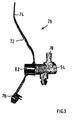
- Such a flexible plastic cable connector 70 is in Figure 3 shown mounted on the fastening device 54, but still open position.
- Such a plastic cable connector 70 may be connected to the standardized receivers 78, 80 projecting away from the base body 58 in different directions, which are preferably formed by an undercut having receiving pins which can be latched into an opening of a fastening portion 82 of a plastic cable connector 70.
- a fastening portion 82 may be formed by a sleeve portion having an insertion opening from which locking projections protrude radially inwardly away, which engage behind the receiving pin 78, 80 in the inserted state.
- the main body 58, the mounting pin 56, the spacer pin 66 and the spigot 78, 80 may be designed as a one-piece body made of plastic.
- the main body 58 may be provided with a through-slot 84 for passing a flexible plastic cable connector 70, which then need not have its own attachment portion.
- fastening devices 54 can be accommodated in a plurality of breathing bores 52, since an air exchange and condensation run are always ensured by means of the connecting channels 64 in the fastening pins 56.
Landscapes
- Engineering & Computer Science (AREA)
- Transportation (AREA)
- Mechanical Engineering (AREA)
- Braking Arrangements (AREA)
- Transmission Of Braking Force In Braking Systems (AREA)
- Quick-Acting Or Multi-Walled Pipe Joints (AREA)
- Clamps And Clips (AREA)
- Valves And Accessory Devices For Braking Systems (AREA)
Description
- Die Erfindung betrifft eine Vorrichtung, die ein Gehäuse mit einer Atmungsbohrung aufweist, wobei das Gehäuse mit einer Befestigungsvorrichtung zum äußeren Befestigen von Kabeln oder Leitungen versehen ist und die Befestigungsvorrichtung einen Befestigungszapfen aufweist, in dem ein Verbindungskanal ausgebildet ist, gemäß dem Oberbegriff von Anspruch 1.
- Ein solche Befestigungsvorrichtung ist in der
JP 2003 168878 A US 5 967 468 A offenbart. Sie hält ein Antennenkabel an einem Turm. - In der bisher unveröffentlichten
DE 10 2004 04 4939 ist eine Befestigungsvorrichtung zum äußeren Befestigen von Kabeln oder Leitungen an einem Gehäuse eines Bremszylinders beschrieben. Sie besteht in einer Befestigungsklemme, welche zum einen an einer ringförmigen Umbördelung eines Gehäuseteils eines Bremszylinders und zum andern über einen in der Atmungsbohrung des Gehäuses einrastbaren Zapfen mit dem Gehäuse verbunden ist. - Demgegenüber ist es die Aufgabe der vorliegenden Erfindung, eine im Hinblick auf ihre Funktionalität verbesserte Befestigungsvorrichtung zur Befestigung von Kabeln oder Leitungen an Gehäusen zur Verfügung zu stellen.
- Diese Aufgabe wird durch die Merkmale von Anspruch 1 gelöst.
- Die Erfindung schlägt vor, dass der Befestigungszapfen in der Atmungsbohrung des Gehäuses verrastet ist, wobei im verrasteten Zustand das Innere des Gehäuses durch den Verbindungskanal mit der Atmosphäre in Verbindung steht. Dann steht im verrasteten Zustand das Innere des Gehäuses mit der Atmosphäre in Verbindung.
- Weil in dem Befestigungszapfen ein Verbindungskanal ausgebildet ist, wird die Atmungsbohrung nicht verschlossen und kann somit weiterhin die Funktion ausführen, für einen Ablauf von Kondenswasser aus dem Inneren des Gehäuses nach außen sowie für einen Luftaustausch zu sorgen. Dies ist insbesondere dann wesentlich, wenn, wie in der Praxis üblich, am Gehäuse eines Bremszylinders eine Vielzahl von Kabeln und Leitungen befestigt sind und demzufolge die Mehrzahl der Atmungsbohrungen als Fixierpunkte für die Befestigungsvorrichtungen dienen müssen, welche andernfalls verschlossen wären und somit durch weitere, die Fertigungskosten erhöhende Atmungsbohrungen ergänzt werden müssten. Insbesondere können mehrere Atmungsbohrungen mit einer solchen Befestigungsvorrichtung versehen sein, ohne dass der Luftaustausch oder der Abfluss von Kondenswasser darunter leidet, so dass Kabel und Leitungen auch an mehreren Stellen am Gehäuse angebunden sein können. Da die Atmungsbohrungen ihre Belüftungs- und Entwässerungsaufgabe dann ungehindert ausüben können, wird die Gefahr von Korrosion im Inneren des Gehäuses reduziert, was insbesondere bei sicherheitsrelevanten Bremszylindern von großem Vorteil ist.
- Durch die in den Unteransprüchen aufgeführten Maßnahmen sind vorteilhafte Weiterbildungen und Verbesserungen der in Anspruch 1 angegebenen Erfindung möglich.
- Besonders bevorzugt ist die Befestigungsvorrichtung lediglich über den Befestigungszapfen am Gehäuse befestigt und der Befestigungszapfen in der Atmungsbohrung derart verrastet, dass die Befestigungsvorrichtung um eine Zapfenachse gegenüber dem Gehäuse schwenkbar ist. Dadurch können sich die Kabel und Leitungen, welche in der Regel eine gewisse Steifigkeit aufweisen, gegenüber dem Gehäuse frei ausrichten, indem die Befestigungsvorrichtung in die jeweilige Richtung schwenkt. Infolgedessen kann eine Umlenkung oder Biegung der Kabel und Leitungen vermieden werden, was aufgrund der Spannungsfreiheit zum einen ihre Lebensdauer erhöht und zum andern eine kurze Verlegelänge ermöglicht, was vor allem bei pneumatischen Leitungen von Bremszylindern von Vorteil ist, welche einen längenabhängigen Strömungswiderstand aufweisen.
- Die Verrastung des Befestigungszapfens mit der Atmungsbohrung des Gehäuses kann beispielsweise dadurch realisiert sein, dass der Befestigungszapfen wenigstens zwei von einem Grundkörper weg ragende, elastisch verformbare Schenkel mit einem zwischengeordneten Schlitz beinhaltet, welcher den Verbindungskanal ausgebildet. Dadurch erfüllt der Befestigungszapfen eine Doppelfunktion, indem er einerseits für die rastbare Befestigung der Befestigungsvorrichtung am Gehäuse sorgt, aber andererseits auch gleichzeitig den Verbindungskanal ausbildet.
- Ein Verschluss des Verbindungskanals bei in der Atmungsbohrung verrastetem Befestigungszapfen wird beispielsweise dadurch verhindert, dass von dem Grundkörper wenigstens ein im verrasteten Zustand eine Außenfläche des Gehäuses kontaktierender Abstandshalter derart wegragt, dass ein sich über die Außenfläche hinaus erstreckender Endabschnitt des Kanals wenigstens seitlich mit der Atmosphäre in Verbindung steht.
- Gemäß einer weiteren bevorzugten Maßnahme kann der Grundkörper weiterhin mit einem Durchgangsschlitz zur Durchführung eines elastischen Kunststoffkabelverbinders versehen sein, welcher die am Gehäuse zu befestigenden Kabel und Leitungen umschlingt. Zusätzlich kann der Grundkörper mit wenigstens zwei standardisierten Aufnahmen für solche elastischen Kunststoffkabelverbinder versehen sein, welche in verschiedene Richtungen weisen. Dann können Kabel und Leitungen gebündelt am Gehäuse befestigt werden, welche sich überkreuzen. In Kombination mit der Schwenkmöglichkeit der Befestigungsvorrichtung ist folglich eine Vielzahl von Richtungen darstellbar, in welchen die Kabel und Leitungen in Bezug zum Gehäuse umlenkungsfrei verlaufen können.
- Besonders bevorzugt sind auch die Kunststoffkabelverbinder mit den standardisierten Aufnahmen verrastbar, beispielsweise dadurch, dass die standardisierten Aufnahmen durch einen hinterschnittenen Querschnitt aufweisende Aufnahmezapfen gebildet werden, welche in Öffnungen von Befestigungsabschnitten der Kunststoffkabelverbinder einrastbar sind.
- Ein Ausführungsbeispiel der Erfindung ist in der Zeichnung dargestellt und in der nachfolgenden Beschreibung näher erläutert. In der Zeichnung zeigt
- Fig.1
- eine Querschnittsdarstellung eines Bremszylinders mit einer Befestigungsvorrichtung gemäß einer bevorzugten Ausführungsform der Erfindung;
- Fig.2
- eine teilweise aufgebrochene Einzeldarstellung der Befestigungsvorrichtung von
Fig.1 . - Fig.3
- eine perspektivische Ansicht der Befestigungsvorrichtung von
Fig.1 mit einem an ihr befestigten elastischen Kunststoffkabelverbinder. - In
Fig.1 ist eine kombinierte Betriebsbrems- und Federspeicherbremsvorrichtung 1 gezeigt. Diese umfasst eine Betriebsbremseinrichtung 2 mit einem Betriebsbremszylinder 4, in dem ein pneumatisch beaufschlagbarer Betriebsbremskolben 6 geführt ist, welcher über eine Betriebsbremskolbenstange 8 beispielsweise eine aus Maßstabsgründen nicht gezeigte Scheibenbremse eines Nutzfahrzeugs betätigt. Weiterhin ist eine Federspeicherbremseinrichtung 10 mit einem Federspeicherbremszylinder 12 vorhanden, in welchem ein durch pneumatischen Druck in einer Federspeicherbremskammer 14 gegen die Federkraft einer Speicherfeder 16 spannbarer Federspeicherbremskolben 18 geführt ist, durch welchen der Betriebsbremskolben 6 in Bremszuspannrichtung beaufschlagbar ist. Der Betriebsbremszylinder 4 und der Federspeicherbremszylinder 12 bilden hintereinander koaxial angeordnet einen Kombibremszylinder 20. - Eine Federspeicherbremskolbenstange 24 des Federspeicherbremskolbens 18 durchragt dichtend eine Durchgangsöffnung 26 in einer Trennwand 28 zwischen dem Federspeicherbremszylinder 12 und dem Betriebsbremszylinder 4 und kann mit ihrer Stirnfläche am Betriebsbremskolben 6 anschlagen. Dieser kann eine außenrandseitig zwischen die Trennwand 28 und einer radial äußeren Schulter 30 am Rand des Betriebsbremszylinders 4 eingespannte und axial bewegliche Membran 32 sowie eine zentrale, mit der Membran 32 verbundene Kolbenscheibe 34 beinhalten (
Fig.2 ). - Die Schulter 30 ist vorzugsweise um mehr als 90 Grad umgebogen, so dass sich eine schräge Kontaktfläche zur Membran 32 hin ergibt. Andererseits ist auch die Trennwand 28 an ihrem radial äußeren Rand mit einer schrägen Kontaktfläche versehen, so dass sich dazwischen ein nach radial außen keilförmig erweiternder Querschnitt ergibt, in welchem der komplementär ausgeformte äußere Rand 36 der Membran 32 formschlüssig gehalten ist. Zur Stabilisierung dieses Formschlusses und zur Verbindung des Betriebsbremszylinders 4 mit dem Federspeicherbremszylinder 12 übergreift ein Rand 42 des Letzteren die Schulter 30 des Betriebsbremszylinders 4 formschlüssig, insbesondere durch eine formschlüssige Umbördelung 44, bei welcher der Rand 42 des Federspeicherbremszylinders 12 plastisch verformt wird.
- In bekannter Weise kann außerdem der Federspeicherbremskolben 18 gegen die Wirkung der Speicherfeder 16 durch Belüften der Federspeicherbremskammer 14 in Lösestellung gebracht werden. Weiterhin kann durch Belüften einer Betriebsbremskammer 38, welche sich zwischen der Trennwand 28 und dem Betriebsbremskolben 6 erstreckt, Letzterer gegen die Wirkung einer sich einerseits am Betriebsbremskolben 6 und andererseits an einer Stirnwand des Betriebsbremszylinders 4 abstützenden Rückholfeder 46 in Zuspannstellung gebracht werden. Nicht zuletzt ist innerhalb der Federspeicherbremskolbenstange 24 eine mechanische Löseeinrichtung 47 integriert, mit welcher die Federspeicherbremseinrichtung 10 bei Druckausfall not- oder hilfsgelöst werden kann.
- Die Funktionsweise einer solchen kombinierten Betriebsbrems- und Federspeicherbremsvorrichtung 1 ist hinlänglich beschrieben worden, beispielsweise in der
DE 10 2004 060 862 A1 , deshalb soll hier nicht weiter darauf eingegangen werden. - Ein zwischen der Trennwand 28 und einer Mantelwand 48 des Federspeicherbremszylinders 12 ausbildete Ringkammer 50 im Inneren der kombinierten Betriebsbrems- und Federspeicherbremsvorrichtung 1 steht mittels mehrerer beispielsweise über den Umfang in der Mantelwand 48 im Bereich der Umbördelung 44 verteilt angeordneter Atmungsbohrungen 52 mit der Atmosphäre in Verbindung.
- Zum äußeren Befestigen von Leitungen, insbesondere von pneumatischen Leitungen oder Kabeln an der kombinierten Betriebsbrems- und Federspeicherbremsvorrichtung 1 ist eine Befestigungsvorrichtung 54 vorgesehen, welche einen Befestigungszapfen 56 umfasst, der in einer der Atmungsbohrungen 52 verrastbar ist. Wie insbesondere aus
Fig.2 hervorgeht, besteht der Befestigungszapfen 54 aus vorzugsweise zwei von einem Grundkörper 58 weg ragenden elastisch verformbaren Schenkeln 60, 62 mit einem zwischengeordneten Schlitz 64. Die Schenkel 60, 62 haben einen endseitig kegelförmigen Querschnitt mit einer Hinterschneidung, so dass sich die Schenkel 60, 62 beim Einführen in eine Atmungsbohrung 52 nach radial innen biegen und nach Erreichen der Einrastposition nach außen elastisch zurückfedern, wodurch die Hinterschneidung hinter einem inneren Rand der Atmungsbohrung 52 einrasten kann und die Befestigungsvorrichtung 54 dadurch am Federspeicherbremszylinder 12 axial gehalten ist. Die Durchmesser des Befestigungszapfens 56 und der Atmungsbohrung 52 sind derart ausgeführt, dass sich die Befestigungsvorrichtung 54 gegenüber dem Federspeicherbremszylinder 12 um die Zapfenachse frei schwenken kann. - Der Schlitz 64 des Befestigungszapfens 56, welcher die elastische Bewegung der Schenkel 60, 62 nach radial innen ermöglicht, bildet gleichzeitig einen Verbindungskanal, über welchen das Innere der Ringkammer 50 mit der Atmosphäre in Verbindung steht. Damit der Schlitz 64 nicht durch die Mantelwand 48 des Federspeicherbremszylinders 12 im einsteckten Zustand des Befestigungszapfens 56 verdeckt wird, ragen von dem Grundkörper 58 beispielsweise zwei eine Außenfläche der Mantelwand 48 des Federspeicherbremszylinders 12 kontaktierende Abstandshalter in Form von Abstandszapfen 66 derart weg, dass ein sich über die Mantelwand 48 hinaus erstreckender Endabschnitt 68 des Schlitzes 64 mit der Atmosphäre seitlich in Verbindung steht, wie anhand von
Fig.2 anschaulich dargestellt ist. Folglich ist der Endabschnitt 68 des Schlitzes nach zwei Seiten hin offen und kann mit der Atmosphäre kommunizieren. Dabei ist der Befestigungszapfen 56 den beiden Abstandszapfen 66 beispielsweise zwischengeordnet. Alternativ könnte sich der Verbindungskanal 64 auch durch den Grundkörper 58 hindurcherstrecken und dann in die Atmosphäre münden. - Weiterhin ist der Grundkörper 58 mit wenigstens zwei standardisierten Aufnahmen für elastische Kunststoffkabelverbinder 70 versehen, welche in verschiedene Richtungen weisen. Elastische Kunststoffkabelverbinder sind hinlänglich bekannt, sie bestehen in einem elastisch biegbaren Kunststoffstreifen 72, mit einer Zunge 74 am einen Ende und einer Schlaufe 76 am anderen Ende, wobei die Oberfläche der Zunge 74 mit Rastvorsprüngen versehen ist, welche in einer Öffnung der Schlaufe 76 derart stufenartig verrastbar sind, dass zum Einschnüren eines Bündels von Kabeln und/oder Leitungen oder auch einzelner Kabel und/oder Leitungen ein beliebiger Umschlingungsdurchmesser eingestellt und zugfest gehalten werden kann. Ein solcher elastische Kunststoffkabelverbinder 70 ist in
Fig.3 in an der Befestigungsvorrichtung 54 montierter, aber noch offener Stellung gezeigt. Ein solcher Kunststoffkabelverbinder 70 kann mit den standardisierten, vom Grundkörper 58 in verschiedenen Richtungen weg ragenden Aufnahmen 78, 80 verbunden sein, welche vorzugsweise durch einen hinterschnittenen Querschnitt aufweisende Aufnahmezapfen gebildet werden, welche in eine Öffnung eines Befestigungsabschnitts 82 eines Kunststoffkabelverbinders 70 einrastbar sind. Ein solcher Befestigungsabschnitt 82 kann durch einen Hülsenabschnitt mit einer Einstecköffnung gebildet sein, von welcher Rastvorsprünge nach radial innen weg ragen, welche die Aufnahmezapfen 78, 80 im eingesteckten Zustand hintergreifen. - Der Grundkörper 58, der Befestigungszapfen 56, die Abstandszapfen 66 sowie die Aufnahmezapfen 78, 80 können als einstückiger Körper aus Kunststoff ausgeführt sein. Zusätzlich kann der Grundkörper 58 mit einem Durchgangsschlitz 84 zur Durchführung eines elastischen Kunststoffkabelverbinders 70 versehen sein, welcher dann keinen eigenen Befestigungsabschnitt aufzuweisen braucht. Nicht zuletzt können in mehreren Atmungsbohrungen 52 solche Befestigungsvorrichtungen 54 aufgenommen sein, da mittels der Verbindungskanäle 64 in den Befestigungszapfen 56 ein Luftaustausch und Kondenswasserablauf stets gewährleistet ist.
-
- 1
- Betriebsbrems - und Federspeicherbremsvorrichtung
- 2
- Betriebsbremseinrichtung
- 4
- Betriebsbremszylinder
- 6
- Betriebsbremskolben
- 8
- Betriebsbremskolbenstange
- 10
- Federspeicherbremseinrichtung
- 12
- Federspeicherbremszylinder
- 14
- Federspeicherbremskammer
- 16
- Speicherfeder
- 18
- Federspeicherbremskolben
- 20
- Kombibremszylinder
- 22
- Befestigungsbolzen
- 24
- Federspeicherbremskolbenstange
- 26
- Durchgangsöffnung
- 28
- Trennwand
- 30
- Schulter
- 32
- Membran
- 34
- Kolbenscheibe
- 36
- Rand
- 38
- Betriebsbremskammer
- 42
- Rand
- 44
- Umbördelung
- 46
- Rückholfeder
- 48
- Mantelwand
- 50
- Ringkammer
- 52
- Atmungsbohrung
- 54
- Befestigungsvonichtung
- 56
- Bfestigungszapfen
- 58
- Grundkörper
- 60
- Schenkel
- 62
- Schenkel
- 64
- Schlitz
- 66
- Abstandszapfen
- 68
- Endabschnitt
- 70
- Kunststoffkabelverbinder
- 72
- Kunststoffstreifen
- 74
- Zunge
- 76
- Schlaufe
- 78
- Aufnahmezapfen
- 80
- Aufnahmezapfen
- 82
- Befestigungsabschnitt
- 84
- Durchgangsschlitz
Claims (8)
- Vorrichtung, die ein Gehäuse mit einer Atmungsbohrung (52) aufweist, wobei das Gehäuse mit einer Befestigungsvorrichtung (54) zum äußeren Befestigen von Kabeln oder Leitungen versehen ist und die Befestigungsvorrichtung (54) einen Befestigungszapfen (56) aufweist, in dem ein Verbindungskanal (64) ausgebildet ist, dadurch gekennzeichnet, dass der Befestigungszapfen (56) in der Atmungsbohrung (52) des Gehäuses (12) verrastet ist, wobei im verrasteten Zustand das Innere (50) des Gehäuses (12) durch den Verbindungskanal (64) mit der Atmosphäre in Verbindung steht.
- Vorrichtung nach Anspruch 1, dadurch gekennzeichnet, dass der Befestigungszapfen (56) in der Atmungsbohrung (52) derart verrastet ist, dass die Befestigungsvorrichtung (54) um eine Zapfenachse gegenüber dem Gehäuse (12) schwenkbar ist.
- Vorrichtung nach Anspruch 1 oder 2, dadurch gekennzeichnet, dass der Befestigungszapfen (56) wenigstens zwei von einem Grundkörper (58) weg ragende, elastisch verformbare Schenkel (60, 62) mit einem zwischengeordneten Schlitz beinhaltet, welcher den Verbindungskanal (64) ausbildet.
- Vorrichtung nach Anspruch 3, dadurch gekennzeichnet, dass von dem Grundkörper (58) wenigstens ein eine Außenfläche des Gehäuses (12) kontaktierender Abstandshalter (66) derart wegragt, dass ein sich über die Außenfläche hinaus erstreckender Endabschnitt (68) des Schlitzes (64) wenigstens seitlich mit der Atmosphäre in Verbindung steht.
- Vorrichtung nach Anspruch 3 oder 4, dadurch gekennzeichnet, dass der Grundkörper (58) weiterhin mit einem Durchgangsschlitz (84) zur Durchführung eines elastischen Kunststoffkabelverbinders (70) versehen ist.
- Vorrichtung nach wenigstens einem der Ansprüche 3 bis 5, dadurch gekennzeichnet, dass der Grundkörper (58) mit wenigstens zwei standardisierten Aufnahmen (78, 80) für elastische Kunststoffkabelverbinder (70) versehen ist, welche in verschiedene Richtungen weisen.
- Vorrichtung nach Anspruch 6, dadurch gekennzeichnet, dass die standardisierten Aufnahmen (78, 80) derart ausgeführt sind, dass der Kunststoffkabelverbinder (70) mit ihnen verrastbar sind.
- Vorrichtung nach Anspruch 7, dadurch gekennzeichnet, dass die standardisierten Aufnahmen (78, 80) durch einen hinterschnittenen Querschnitt aufweisende Aufnahmezapfen gebildet werden, welche in Öffnungen von Befestigungsabschnitten (82) der Kunststoffkabelverbinder (70) einrastbar sind.
Priority Applications (1)
| Application Number | Priority Date | Filing Date | Title |
|---|---|---|---|
| PL06724375T PL1874603T3 (pl) | 2005-04-19 | 2006-04-18 | Urządzenie mocujące do zewnętrznego mocowania kabli lub przewodów na obudowach |
Applications Claiming Priority (2)
| Application Number | Priority Date | Filing Date | Title |
|---|---|---|---|
| DE102005018038A DE102005018038A1 (de) | 2005-04-19 | 2005-04-19 | Befestigungsvorrichtung zum äußeren Befestigen von Kabeln oder Leitungen an Gehäusen |
| PCT/EP2006/003506 WO2006111342A1 (de) | 2005-04-19 | 2006-04-18 | Befestigungsvorrichtung zum äusseren befestigen von kabeln oder leitungen an gehäusen |
Publications (2)
| Publication Number | Publication Date |
|---|---|
| EP1874603A1 EP1874603A1 (de) | 2008-01-09 |
| EP1874603B1 true EP1874603B1 (de) | 2009-07-15 |
Family
ID=36616746
Family Applications (1)
| Application Number | Title | Priority Date | Filing Date |
|---|---|---|---|
| EP06724375A Expired - Lifetime EP1874603B1 (de) | 2005-04-19 | 2006-04-18 | Befestigungsvorrichtung zum äusseren befestigen von kabeln oder leitungen an gehäusen |
Country Status (13)
| Country | Link |
|---|---|
| US (1) | US8397882B2 (de) |
| EP (1) | EP1874603B1 (de) |
| JP (1) | JP5001935B2 (de) |
| CN (1) | CN101163616B (de) |
| BR (1) | BRPI0610598B1 (de) |
| CA (1) | CA2606455A1 (de) |
| DE (2) | DE102005018038A1 (de) |
| DK (1) | DK1874603T3 (de) |
| ES (1) | ES2326997T3 (de) |
| MX (1) | MX2007012868A (de) |
| PL (1) | PL1874603T3 (de) |
| PT (1) | PT1874603E (de) |
| WO (1) | WO2006111342A1 (de) |
Families Citing this family (3)
| Publication number | Priority date | Publication date | Assignee | Title |
|---|---|---|---|---|
| DE102007008730A1 (de) * | 2007-02-22 | 2008-08-28 | Knorr-Bremse Systeme für Nutzfahrzeuge GmbH | Membrane für druckmittelbetätigte Bremszylinder mit Zentrierring |
| DE102013014449A1 (de) * | 2013-08-30 | 2015-03-05 | Knorr-Bremse Systeme für Nutzfahrzeuge GmbH | Druckluftbetätigter Bremszylinder mit abgedeckter Be- und Entlüftungsbohrung |
| US10767715B2 (en) | 2018-10-11 | 2020-09-08 | Bendix Spicer Foundation Brake Llc | Pivotable actuator mounting device |
Family Cites Families (13)
| Publication number | Priority date | Publication date | Assignee | Title |
|---|---|---|---|---|
| US5377579A (en) * | 1993-06-15 | 1995-01-03 | Nai Anchorlok, Inc. | Fluid-operated spring brake atuator with funnel-shaped pressure plate |
| US5393021A (en) * | 1994-03-07 | 1995-02-28 | Cablewave Systems | Cable hanger |
| JPH0874895A (ja) * | 1994-09-08 | 1996-03-19 | Aisin Seiki Co Ltd | ディスクブレーキ用プロテクタ |
| JPH08200412A (ja) * | 1995-01-19 | 1996-08-06 | Sumitomo Electric Ind Ltd | ライニング摩耗検出装置のリード線案内装置 |
| JPH09190860A (ja) | 1995-12-22 | 1997-07-22 | Whitaker Corp:The | 基板取付装置及びそれを使用する電気コネクタ |
| JPH10122217A (ja) * | 1996-10-22 | 1998-05-12 | Suzuki Motor Corp | 長尺物のクランプ構造 |
| US5799830A (en) * | 1996-11-08 | 1998-09-01 | Carroll; David C. | Pressure vessel access port |
| US5967468A (en) * | 1998-01-26 | 1999-10-19 | Tennaplex Systems, Inc. | Cable retaining clamp |
| JP4198288B2 (ja) * | 1998-12-04 | 2008-12-17 | アスモ株式会社 | 車両用電動ブレーキ装置 |
| US6389954B1 (en) * | 1999-11-19 | 2002-05-21 | Tse Brakes, Inc. | Removable filter plug for spring brake actuator |
| NL1014510C2 (nl) * | 2000-02-28 | 2001-08-29 | Johannes Gerardus Michel Berna | Axiaal in lengte variabele koppeling voor voertuigremleiding. |
| JP2003168878A (ja) * | 2001-09-18 | 2003-06-13 | Takeuchi Kogyo Kk | スナップ構造 |
| DE102004044939B4 (de) | 2004-04-21 | 2007-08-16 | Knorr-Bremse Systeme für Nutzfahrzeuge GmbH | Befestigungsklemme für Bremszylinder |
-
2005
- 2005-04-19 DE DE102005018038A patent/DE102005018038A1/de not_active Withdrawn
-
2006
- 2006-04-18 US US11/911,861 patent/US8397882B2/en not_active Expired - Fee Related
- 2006-04-18 ES ES06724375T patent/ES2326997T3/es not_active Expired - Lifetime
- 2006-04-18 CN CN2006800131001A patent/CN101163616B/zh not_active Expired - Fee Related
- 2006-04-18 PL PL06724375T patent/PL1874603T3/pl unknown
- 2006-04-18 WO PCT/EP2006/003506 patent/WO2006111342A1/de not_active Ceased
- 2006-04-18 PT PT06724375T patent/PT1874603E/pt unknown
- 2006-04-18 CA CA002606455A patent/CA2606455A1/en not_active Abandoned
- 2006-04-18 DE DE502006004239T patent/DE502006004239D1/de not_active Expired - Lifetime
- 2006-04-18 BR BRPI0610598-0A patent/BRPI0610598B1/pt not_active IP Right Cessation
- 2006-04-18 MX MX2007012868A patent/MX2007012868A/es active IP Right Grant
- 2006-04-18 EP EP06724375A patent/EP1874603B1/de not_active Expired - Lifetime
- 2006-04-18 JP JP2008506987A patent/JP5001935B2/ja not_active Expired - Fee Related
- 2006-04-18 DK DK06724375T patent/DK1874603T3/da active
Also Published As
| Publication number | Publication date |
|---|---|
| DE102005018038A1 (de) | 2006-10-26 |
| US20080283685A1 (en) | 2008-11-20 |
| DE502006004239D1 (de) | 2009-08-27 |
| JP2008537076A (ja) | 2008-09-11 |
| EP1874603A1 (de) | 2008-01-09 |
| JP5001935B2 (ja) | 2012-08-15 |
| CN101163616B (zh) | 2012-06-27 |
| US8397882B2 (en) | 2013-03-19 |
| HK1118771A1 (en) | 2009-02-20 |
| PT1874603E (pt) | 2009-08-03 |
| CN101163616A (zh) | 2008-04-16 |
| PL1874603T3 (pl) | 2009-12-31 |
| MX2007012868A (es) | 2008-01-11 |
| ES2326997T3 (es) | 2009-10-22 |
| WO2006111342A1 (de) | 2006-10-26 |
| DK1874603T3 (da) | 2009-08-24 |
| CA2606455A1 (en) | 2006-10-26 |
| BRPI0610598B1 (pt) | 2018-04-24 |
| BRPI0610598A2 (pt) | 2010-07-06 |
Similar Documents
| Publication | Publication Date | Title |
|---|---|---|
| DE69529193T2 (de) | Stecker mit abgedichteten Kontakten | |
| EP4127543B1 (de) | Steckverbinder mit vormontagesicherung | |
| EP1635103B1 (de) | Lösbare Steckverbindung für Rohrleitungen od. dgl. | |
| EP2712413B1 (de) | Anschlussvorrichtung zum anschliessen einer fluidleitung | |
| EP2757299A1 (de) | Rohrklemmanordnung | |
| DE102018113967A1 (de) | Dichtschnittstelle für eine Lufttrocknungskartusche und einen Sockel für eine Lufttrocknungskartusche | |
| EP3995330A1 (de) | Druckhalteventil für eine luftfeder und luftfeder umfassend das druckhalteventil | |
| DE9400555U1 (de) | Anschlußteil für einen Betätigungszug | |
| EP4405606B1 (de) | Steckverbinder mit vormontagesicherung | |
| EP1874603A1 (de) | Befestigungsvorrichtung zum äusseren befestigen von kabeln oder leitungen an gehäusen | |
| EP3153755B1 (de) | Quetschflansch mit montagekontrolle | |
| DE102012000215A1 (de) | Rückschlagventil | |
| DE10215608A1 (de) | Rohrverbinder | |
| WO2010103059A2 (de) | Einbaurahmen zur aufnahme eines geräts in einer einbauöffnung | |
| DE102019000444A1 (de) | Bremsbelaganordnung für eine Fahrzeugscheibenbremse | |
| DE102014109270A1 (de) | Leitungsfixierung und Verfahren zum Fixieren einer elektrischen Leitung an einem Stecker | |
| DE19750083B4 (de) | Fluidische Steckverbindung | |
| DE102015109539A1 (de) | Dichtmodul | |
| EP2559929B1 (de) | Leitungsdurchführung mit Prüfvolumen | |
| DE202011105202U1 (de) | Elektrischer Steckverbinder | |
| WO2017206982A1 (de) | Hydraulikleitung | |
| DE102016113708A1 (de) | Steckverbindung | |
| DE102009021350A1 (de) | Kolbenstangenanbindung | |
| EP1472485A1 (de) | Anschlusseinrichtung, anschlussstück und kontaktklammer für eine fluidleitung | |
| EP2982894B1 (de) | Rohrklemmanordnung |
Legal Events
| Date | Code | Title | Description |
|---|---|---|---|
| PUAI | Public reference made under article 153(3) epc to a published international application that has entered the european phase |
Free format text: ORIGINAL CODE: 0009012 |
|
| 17P | Request for examination filed |
Effective date: 20071119 |
|
| AK | Designated contracting states |
Kind code of ref document: A1 Designated state(s): AT BE BG CH CY CZ DE DK EE ES FI FR GB GR HU IE IS IT LI LT LU LV MC NL PL PT RO SE SI SK TR |
|
| 17Q | First examination report despatched |
Effective date: 20080320 |
|
| DAX | Request for extension of the european patent (deleted) | ||
| GRAP | Despatch of communication of intention to grant a patent |
Free format text: ORIGINAL CODE: EPIDOSNIGR1 |
|
| GRAS | Grant fee paid |
Free format text: ORIGINAL CODE: EPIDOSNIGR3 |
|
| GRAA | (expected) grant |
Free format text: ORIGINAL CODE: 0009210 |
|
| AK | Designated contracting states |
Kind code of ref document: B1 Designated state(s): AT BE BG CH CY CZ DE DK EE ES FI FR GB GR HU IE IS IT LI LT LU LV MC NL PL PT RO SE SI SK TR |
|
| REG | Reference to a national code |
Ref country code: GB Ref legal event code: FG4D Free format text: NOT ENGLISH Ref country code: CH Ref legal event code: EP |
|
| REG | Reference to a national code |
Ref country code: PT Ref legal event code: SC4A Free format text: AVAILABILITY OF NATIONAL TRANSLATION Effective date: 20090727 |
|
| REG | Reference to a national code |
Ref country code: IE Ref legal event code: FG4D |
|
| REG | Reference to a national code |
Ref country code: DK Ref legal event code: T3 |
|
| REF | Corresponds to: |
Ref document number: 502006004239 Country of ref document: DE Date of ref document: 20090827 Kind code of ref document: P |
|
| REG | Reference to a national code |
Ref country code: SE Ref legal event code: TRGR |
|
| REG | Reference to a national code |
Ref country code: ES Ref legal event code: FG2A Ref document number: 2326997 Country of ref document: ES Kind code of ref document: T3 |
|
| REG | Reference to a national code |
Ref country code: PL Ref legal event code: T3 |
|
| PG25 | Lapsed in a contracting state [announced via postgrant information from national office to epo] |
Ref country code: FI Free format text: LAPSE BECAUSE OF FAILURE TO SUBMIT A TRANSLATION OF THE DESCRIPTION OR TO PAY THE FEE WITHIN THE PRESCRIBED TIME-LIMIT Effective date: 20090715 Ref country code: LT Free format text: LAPSE BECAUSE OF FAILURE TO SUBMIT A TRANSLATION OF THE DESCRIPTION OR TO PAY THE FEE WITHIN THE PRESCRIBED TIME-LIMIT Effective date: 20090715 Ref country code: IS Free format text: LAPSE BECAUSE OF FAILURE TO SUBMIT A TRANSLATION OF THE DESCRIPTION OR TO PAY THE FEE WITHIN THE PRESCRIBED TIME-LIMIT Effective date: 20091115 |
|
| REG | Reference to a national code |
Ref country code: IE Ref legal event code: FD4D |
|
| PG25 | Lapsed in a contracting state [announced via postgrant information from national office to epo] |
Ref country code: SI Free format text: LAPSE BECAUSE OF FAILURE TO SUBMIT A TRANSLATION OF THE DESCRIPTION OR TO PAY THE FEE WITHIN THE PRESCRIBED TIME-LIMIT Effective date: 20090715 Ref country code: LV Free format text: LAPSE BECAUSE OF FAILURE TO SUBMIT A TRANSLATION OF THE DESCRIPTION OR TO PAY THE FEE WITHIN THE PRESCRIBED TIME-LIMIT Effective date: 20090715 |
|
| REG | Reference to a national code |
Ref country code: HU Ref legal event code: AG4A Ref document number: E006565 Country of ref document: HU |
|
| PG25 | Lapsed in a contracting state [announced via postgrant information from national office to epo] |
Ref country code: BG Free format text: LAPSE BECAUSE OF FAILURE TO SUBMIT A TRANSLATION OF THE DESCRIPTION OR TO PAY THE FEE WITHIN THE PRESCRIBED TIME-LIMIT Effective date: 20091015 |
|
| PG25 | Lapsed in a contracting state [announced via postgrant information from national office to epo] |
Ref country code: RO Free format text: LAPSE BECAUSE OF FAILURE TO SUBMIT A TRANSLATION OF THE DESCRIPTION OR TO PAY THE FEE WITHIN THE PRESCRIBED TIME-LIMIT Effective date: 20090715 Ref country code: IE Free format text: LAPSE BECAUSE OF FAILURE TO SUBMIT A TRANSLATION OF THE DESCRIPTION OR TO PAY THE FEE WITHIN THE PRESCRIBED TIME-LIMIT Effective date: 20090715 Ref country code: EE Free format text: LAPSE BECAUSE OF FAILURE TO SUBMIT A TRANSLATION OF THE DESCRIPTION OR TO PAY THE FEE WITHIN THE PRESCRIBED TIME-LIMIT Effective date: 20090715 |
|
| PLBE | No opposition filed within time limit |
Free format text: ORIGINAL CODE: 0009261 |
|
| STAA | Information on the status of an ep patent application or granted ep patent |
Free format text: STATUS: NO OPPOSITION FILED WITHIN TIME LIMIT |
|
| PG25 | Lapsed in a contracting state [announced via postgrant information from national office to epo] |
Ref country code: SK Free format text: LAPSE BECAUSE OF FAILURE TO SUBMIT A TRANSLATION OF THE DESCRIPTION OR TO PAY THE FEE WITHIN THE PRESCRIBED TIME-LIMIT Effective date: 20090715 |
|
| 26N | No opposition filed |
Effective date: 20100416 |
|
| PG25 | Lapsed in a contracting state [announced via postgrant information from national office to epo] |
Ref country code: GR Free format text: LAPSE BECAUSE OF FAILURE TO SUBMIT A TRANSLATION OF THE DESCRIPTION OR TO PAY THE FEE WITHIN THE PRESCRIBED TIME-LIMIT Effective date: 20091016 |
|
| PG25 | Lapsed in a contracting state [announced via postgrant information from national office to epo] |
Ref country code: MC Free format text: LAPSE BECAUSE OF NON-PAYMENT OF DUE FEES Effective date: 20100430 |
|
| REG | Reference to a national code |
Ref country code: CH Ref legal event code: PL |
|
| PG25 | Lapsed in a contracting state [announced via postgrant information from national office to epo] |
Ref country code: CH Free format text: LAPSE BECAUSE OF NON-PAYMENT OF DUE FEES Effective date: 20100430 Ref country code: LI Free format text: LAPSE BECAUSE OF NON-PAYMENT OF DUE FEES Effective date: 20100430 |
|
| PGFP | Annual fee paid to national office [announced via postgrant information from national office to epo] |
Ref country code: ES Payment date: 20110419 Year of fee payment: 6 Ref country code: PT Payment date: 20110411 Year of fee payment: 6 |
|
| PGFP | Annual fee paid to national office [announced via postgrant information from national office to epo] |
Ref country code: BE Payment date: 20110419 Year of fee payment: 6 |
|
| PG25 | Lapsed in a contracting state [announced via postgrant information from national office to epo] |
Ref country code: CY Free format text: LAPSE BECAUSE OF FAILURE TO SUBMIT A TRANSLATION OF THE DESCRIPTION OR TO PAY THE FEE WITHIN THE PRESCRIBED TIME-LIMIT Effective date: 20090715 |
|
| PG25 | Lapsed in a contracting state [announced via postgrant information from national office to epo] |
Ref country code: LU Free format text: LAPSE BECAUSE OF NON-PAYMENT OF DUE FEES Effective date: 20100418 |
|
| REG | Reference to a national code |
Ref country code: PT Ref legal event code: MM4A Free format text: LAPSE DUE TO NON-PAYMENT OF FEES Effective date: 20121018 |
|
| BERE | Be: lapsed |
Owner name: KNORR-BREMSE SYSTEME FUR NUTZFAHRZEUGE G.M.B.H. Effective date: 20120430 |
|
| PG25 | Lapsed in a contracting state [announced via postgrant information from national office to epo] |
Ref country code: TR Free format text: LAPSE BECAUSE OF FAILURE TO SUBMIT A TRANSLATION OF THE DESCRIPTION OR TO PAY THE FEE WITHIN THE PRESCRIBED TIME-LIMIT Effective date: 20090715 |
|
| PG25 | Lapsed in a contracting state [announced via postgrant information from national office to epo] |
Ref country code: BE Free format text: LAPSE BECAUSE OF NON-PAYMENT OF DUE FEES Effective date: 20120430 |
|
| PG25 | Lapsed in a contracting state [announced via postgrant information from national office to epo] |
Ref country code: PT Free format text: LAPSE BECAUSE OF NON-PAYMENT OF DUE FEES Effective date: 20121018 |
|
| REG | Reference to a national code |
Ref country code: ES Ref legal event code: FD2A Effective date: 20131021 |
|
| PG25 | Lapsed in a contracting state [announced via postgrant information from national office to epo] |
Ref country code: ES Free format text: LAPSE BECAUSE OF NON-PAYMENT OF DUE FEES Effective date: 20120419 |
|
| REG | Reference to a national code |
Ref country code: FR Ref legal event code: PLFP Year of fee payment: 11 |
|
| REG | Reference to a national code |
Ref country code: FR Ref legal event code: PLFP Year of fee payment: 12 |
|
| REG | Reference to a national code |
Ref country code: FR Ref legal event code: PLFP Year of fee payment: 13 |
|
| PGFP | Annual fee paid to national office [announced via postgrant information from national office to epo] |
Ref country code: CZ Payment date: 20180405 Year of fee payment: 13 Ref country code: DK Payment date: 20180424 Year of fee payment: 13 |
|
| PGFP | Annual fee paid to national office [announced via postgrant information from national office to epo] |
Ref country code: HU Payment date: 20180409 Year of fee payment: 13 |
|
| PGFP | Annual fee paid to national office [announced via postgrant information from national office to epo] |
Ref country code: IT Payment date: 20190419 Year of fee payment: 14 |
|
| PGFP | Annual fee paid to national office [announced via postgrant information from national office to epo] |
Ref country code: SE Payment date: 20190425 Year of fee payment: 14 Ref country code: FR Payment date: 20190423 Year of fee payment: 14 |
|
| PGFP | Annual fee paid to national office [announced via postgrant information from national office to epo] |
Ref country code: GB Payment date: 20190424 Year of fee payment: 14 |
|
| REG | Reference to a national code |
Ref country code: DK Ref legal event code: EBP Effective date: 20190430 |
|
| REG | Reference to a national code |
Ref country code: AT Ref legal event code: MM01 Ref document number: 436418 Country of ref document: AT Kind code of ref document: T Effective date: 20190418 |
|
| PG25 | Lapsed in a contracting state [announced via postgrant information from national office to epo] |
Ref country code: CZ Free format text: LAPSE BECAUSE OF NON-PAYMENT OF DUE FEES Effective date: 20190418 Ref country code: AT Free format text: LAPSE BECAUSE OF NON-PAYMENT OF DUE FEES Effective date: 20190418 Ref country code: HU Free format text: LAPSE BECAUSE OF NON-PAYMENT OF DUE FEES Effective date: 20190419 |
|
| PG25 | Lapsed in a contracting state [announced via postgrant information from national office to epo] |
Ref country code: DK Free format text: LAPSE BECAUSE OF NON-PAYMENT OF DUE FEES Effective date: 20190430 |
|
| PG25 | Lapsed in a contracting state [announced via postgrant information from national office to epo] |
Ref country code: SE Free format text: LAPSE BECAUSE OF NON-PAYMENT OF DUE FEES Effective date: 20200419 Ref country code: FR Free format text: LAPSE BECAUSE OF NON-PAYMENT OF DUE FEES Effective date: 20200430 |
|
| GBPC | Gb: european patent ceased through non-payment of renewal fee |
Effective date: 20200418 |
|
| PG25 | Lapsed in a contracting state [announced via postgrant information from national office to epo] |
Ref country code: GB Free format text: LAPSE BECAUSE OF NON-PAYMENT OF DUE FEES Effective date: 20200418 |
|
| PG25 | Lapsed in a contracting state [announced via postgrant information from national office to epo] |
Ref country code: IT Free format text: LAPSE BECAUSE OF NON-PAYMENT OF DUE FEES Effective date: 20200418 |
|
| PGFP | Annual fee paid to national office [announced via postgrant information from national office to epo] |
Ref country code: NL Payment date: 20210421 Year of fee payment: 16 |
|
| REG | Reference to a national code |
Ref country code: NL Ref legal event code: MM Effective date: 20220501 |
|
| PG25 | Lapsed in a contracting state [announced via postgrant information from national office to epo] |
Ref country code: NL Free format text: LAPSE BECAUSE OF NON-PAYMENT OF DUE FEES Effective date: 20220501 |
|
| P01 | Opt-out of the competence of the unified patent court (upc) registered |
Effective date: 20230523 |
|
| PGFP | Annual fee paid to national office [announced via postgrant information from national office to epo] |
Ref country code: PL Payment date: 20250325 Year of fee payment: 20 |
|
| PGFP | Annual fee paid to national office [announced via postgrant information from national office to epo] |
Ref country code: DE Payment date: 20250428 Year of fee payment: 20 |
|
| REG | Reference to a national code |
Ref country code: DE Ref legal event code: R071 Ref document number: 502006004239 Country of ref document: DE |