EP1876330A2 - Vereinfachtes Schmiersystem bei trockener Ölwanne und Verbrennungsmotor, der ein solches System umfasst - Google Patents
Vereinfachtes Schmiersystem bei trockener Ölwanne und Verbrennungsmotor, der ein solches System umfasst Download PDFInfo
- Publication number
- EP1876330A2 EP1876330A2 EP07301035A EP07301035A EP1876330A2 EP 1876330 A2 EP1876330 A2 EP 1876330A2 EP 07301035 A EP07301035 A EP 07301035A EP 07301035 A EP07301035 A EP 07301035A EP 1876330 A2 EP1876330 A2 EP 1876330A2
- Authority
- EP
- European Patent Office
- Prior art keywords
- pump
- engine
- pressure pump
- pressure
- dewatering
- Prior art date
- Legal status (The legal status is an assumption and is not a legal conclusion. Google has not performed a legal analysis and makes no representation as to the accuracy of the status listed.)
- Withdrawn
Links
Images

Classifications
-
- F—MECHANICAL ENGINEERING; LIGHTING; HEATING; WEAPONS; BLASTING
- F01—MACHINES OR ENGINES IN GENERAL; ENGINE PLANTS IN GENERAL; STEAM ENGINES
- F01M—LUBRICATING OF MACHINES OR ENGINES IN GENERAL; LUBRICATING INTERNAL COMBUSTION ENGINES; CRANKCASE VENTILATING
- F01M1/00—Pressure lubrication
- F01M1/12—Closed-circuit lubricating systems not provided for in groups F01M1/02 - F01M1/10
-
- F—MECHANICAL ENGINEERING; LIGHTING; HEATING; WEAPONS; BLASTING
- F01—MACHINES OR ENGINES IN GENERAL; ENGINE PLANTS IN GENERAL; STEAM ENGINES
- F01M—LUBRICATING OF MACHINES OR ENGINES IN GENERAL; LUBRICATING INTERNAL COMBUSTION ENGINES; CRANKCASE VENTILATING
- F01M1/00—Pressure lubrication
- F01M1/12—Closed-circuit lubricating systems not provided for in groups F01M1/02 - F01M1/10
- F01M2001/126—Dry-sumps
Definitions
- the present invention relates to a dry sump lubrication system for an internal combustion engine comprising a pressure pump for supplying a pressure lubricating liquid to a high-pressure lubricating circuit of the engine, from a reservoir of lubricating liquid, and a dewatering pump for sucking the lubricating liquid which has fallen into the engine sump, called the oil sump, and for driving it into said reservoir.
- the invention also relates to an internal combustion engine comprising such a system and a motor vehicle comprising such a motor.
- the suction strainer of the oil pump which feeds the lubrication system from the oil pan, may then be in conditions where it no longer bathes in the oil. This results in a defusing of the oil pump and destruction of the motor by default lubrication.
- the dry sump lubrication of an engine is conventionally performed by a pressurized circulation, in the engine lubrication circuit, of oil pulsed by means of a pressure pump into a separate reservoir of the oil sump.
- Oil that circulates under pressure in the lubrication system lubricates the surfaces in relative motion of the engine and then falls by gravity into the engine oil sump where it is immediately sucked by a dewatering pump to the separate oil reservoir .
- the oil accumulated in this tank is then sucked back by the pressure pump and then discharged into the lubrication circuit.
- the pressure pump and the dewatering pump generate a large amount of space in the engine.
- the assembly time of these two pumps is long and the number of engine parts necessary for the rotational drive of each of these two pumps is important.
- the present invention proposes a new dry sump lubrication system of reduced size for which the rotational drive of the pumps requires a reduced number of parts.
- the invention proposes a dry sump lubrication system as defined in the introduction, in which the pressure pump and the dewatering pump have a common axis of rotation.
- the pressure and drying pumps are thus able to be arranged in series on the same rotary drive shaft, which reduces the space requirement in the engine as well as the number of parts necessary for the rotary drive of said pumps. .
- the pressure pump and the dewatering pump comprise a common structural part.
- the pressure pump and the dewatering pump each having a body and a cover, a portion of the body of the pressure pump forms the cover of the dewatering pump.
- the body of the pressure pump is attached to the body of the dewatering pump.
- the cover of the pressure pump is attached to the body of the pressure pump.
- the body and the cover of the pressure pump and the dewatering pump are obtained by casting.
- the invention also relates to an internal combustion engine comprising a sump lubrication system as described above, in which the two pumps are mounted on the same rotary drive shaft whose axis coincides with the common axis of rotation of the first and the second pump.
- the pressure pump of the dry sump lubrication system is connected to a high pressure lubrication circuit of the engine which comprises a feed channel opening into the engine.
- lubricating liquid reservoir and, secondly, the bilge pump is connected to a suction channel which opens into the engine oil sump and to a discharge channel which opens into the lubricating liquid reservoir.
- the feed channel of the engine lubrication circuit is connected to a strainer which opens into the lubricating liquid reservoir.
- the invention also relates to a motor vehicle in which there is provided an internal combustion engine as described above.
- FIGs 1 to 5 there is shown a motor vehicle internal combustion engine which comprises a dry sump lubrication system.
- the internal combustion engine comprises a plurality of cylinder barrels arranged in a horizontal configuration on the vehicle.
- the engine housing or engine block, comprises the cylinder housing (not shown), or cylinder block, and the oil sump 40, or crankcase lower, which corresponds to the lower part of the engine housing located under the cylinder block.
- the dry sump lubrication system comprises two pumps 11, 12, namely a pressure pump 11 and a dewatering pump 12.
- the dewatering pump and / or the pressure pump may be vane pumps, trochoid pumps, or gear pumps.
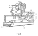
- the pressure pump 11 shown more particularly in FIG. 5, supplies an oil to a high-pressure lubricating circuit 15 of the engine from a reservoir 30 via a supply channel 9 connected to a strainer 13.
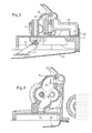
- the dewatering pump 12 shown more particularly in FIGS. 3 and 4, is connected to a suction channel 21 which opens into the oil sump 40 of the engine and to a delivery channel 22 which opens into the tank 30. It then enables the tank 30 to be supplied with oil from the oil sump 40 via the suction channel 21 and the discharge channel 22.
- the mouth 14 of the suction channel 21 is located at the lowest point of the oil sump 40. More particularly, this mouth 14 dipped in the oil of the sump 40 which accumulates in a portion 41 in the form of bowl of oil sump 40.
- the pressure pump 11 and the dewatering pump 12 have a common axis A1 of rotation.
- the two pumps 11, 12 are mounted on one and the same rotation drive shaft whose axis is of axis A1.
- This shaft 5 is connected by a gear system to the crankshaft of the engine.
- the pressure pump 11 and the dewatering pump 12 each comprise a body 82, 81 and a cover 70, 83.
- the cover of the dewatering pump 12 is formed by a part 83 of the body 82 of the pressure pump 11. Thanks to the common structural part 83 of the two pumps 11, 12, on the one hand, the weight of the lubrication system is reduced and, on the other hand, a significant space saving is obtained. in the engine.
- the body 82 of the pressure pump 11 is attached to the body 81 of the dewatering pump 12 and is closed by the cover 70 attached thereto.
- the two pumps 11, 12 form a single piece easily mountable in the engine.
- the body 82, 81 and the cover 70, 83 of the pressure pump 11 and the dewatering pump 12 are obtained by casting.
- the high pressure lubrication circuit 15 comprises, inter alia, a main ramp (not shown) disposed in the cylinder block of the engine which allows the lubrication of the crankshaft bearings and a distribution manifold (not shown) which allows the lubrication of the crankcase. 'camshaft. Some oil may also leave the main boom to irrigate the breech (not shown). The oil thus dispersed in the engine is then collected by gravitation in the oil sump 40.
- the dewatering pump 12 draws, through the mouth 14 of the suction channel 21, the oil that has fallen into the oil sump 40 of the engine and accumulates in its portion 41 in the form of a bowl.
- the oil sucked reaches the oil inlet 23 of the dewatering pump 12 and is discharged through the discharge channel 22 into the tank 30 ( Figures 3 and 4).
- the oil tank 30, or oil tank is closed and is integrated in the lower part of the engine casing.
- a wire 43 disposed in the oil sump 40 separates the lower part of the oil sump 40 which collects the oil that has fallen after passing through the high pressure lubrication circuit 15, of the tank 30.
Landscapes
- Engineering & Computer Science (AREA)
- Mechanical Engineering (AREA)
- General Engineering & Computer Science (AREA)
- Lubrication Of Internal Combustion Engines (AREA)
- Lubrication Details And Ventilation Of Internal Combustion Engines (AREA)
Applications Claiming Priority (1)
| Application Number | Priority Date | Filing Date | Title |
|---|---|---|---|
| FR0605808A FR2903139A1 (fr) | 2006-06-28 | 2006-06-28 | Systeme de lubrification a carter sec simplifie et moteur a combustion interne comprenant un tel systeme |
Publications (2)
| Publication Number | Publication Date |
|---|---|
| EP1876330A2 true EP1876330A2 (de) | 2008-01-09 |
| EP1876330A3 EP1876330A3 (de) | 2010-08-11 |
Family
ID=37907992
Family Applications (1)
| Application Number | Title | Priority Date | Filing Date |
|---|---|---|---|
| EP07301035A Withdrawn EP1876330A3 (de) | 2006-06-28 | 2007-05-14 | Vereinfachtes Schmiersystem bei trockener Ölwanne und Verbrennungsmotor, der ein solches System umfasst |
Country Status (2)
| Country | Link |
|---|---|
| EP (1) | EP1876330A3 (de) |
| FR (1) | FR2903139A1 (de) |
Family Cites Families (6)
| Publication number | Priority date | Publication date | Assignee | Title |
|---|---|---|---|---|
| US6314934B1 (en) * | 1999-09-04 | 2001-11-13 | Honda Giken Kogyo Kabushiki Kaisha | Lubricating device for internal combustion engine |
| JP2001355579A (ja) * | 2000-06-12 | 2001-12-26 | Sanshin Ind Co Ltd | エンジン用オイルポンプの構造 |
| US6679692B1 (en) * | 2002-07-12 | 2004-01-20 | James J. Feuling | Oil pump |
| JP2005016510A (ja) * | 2003-06-03 | 2005-01-20 | Yamaha Motor Co Ltd | エンジンの潤滑装置 |
| JP2005163570A (ja) * | 2003-12-01 | 2005-06-23 | Ihara Seisakusho:Kk | 内燃機関の潤滑装置 |
| JP4583185B2 (ja) * | 2004-03-04 | 2010-11-17 | 本田技研工業株式会社 | 多気筒内燃機関 |
-
2006
- 2006-06-28 FR FR0605808A patent/FR2903139A1/fr active Pending
-
2007
- 2007-05-14 EP EP07301035A patent/EP1876330A3/de not_active Withdrawn
Also Published As
| Publication number | Publication date |
|---|---|
| FR2903139A1 (fr) | 2008-01-04 |
| EP1876330A3 (de) | 2010-08-11 |
Similar Documents
| Publication | Publication Date | Title |
|---|---|---|
| US8011342B2 (en) | Wet oil sump for four cycle engine | |
| US6047667A (en) | Motorcycle camshaft support plate | |
| EP0260174A1 (de) | Einrichtung eines Balanciergerätes in einem Hubkolbenmotorgehäuse | |
| US6116205A (en) | Motorcycle lubrication system | |
| US4911119A (en) | Oil pump mounting system for internal combustion engines | |
| JPH10212915A (ja) | 船外機の潤滑装置 | |
| JP2006037965A (ja) | 内燃機関及び自動車 | |
| US20090194369A1 (en) | Lubrication system for outboard motor | |
| FR2903139A1 (fr) | Systeme de lubrification a carter sec simplifie et moteur a combustion interne comprenant un tel systeme | |
| JP3464154B2 (ja) | 内燃機関の潤滑装置 | |
| JP3873817B2 (ja) | 燃料噴射ポンプ | |
| JP7819535B2 (ja) | 内燃機関のポンプ構造 | |
| US20230080102A1 (en) | Pump System | |
| WO2006095104A1 (fr) | Dispositif de circulation d'huile pour moteur a combustion interne | |
| JPH10103036A (ja) | 内燃機関のオイルポンプ装置 | |
| KR100217987B1 (ko) | 원뿔 격판을 갖는 자동차 오일팬의 오일 흡입 파이프 | |
| JPH0364609A (ja) | 内燃機関の潤滑装置 | |
| JP2001140618A (ja) | ドライサンプ式エンジンの潤滑装置 | |
| JP4066677B2 (ja) | エンジンの潤滑装置 | |
| JP2556142Y2 (ja) | ディーゼルエンジンの燃料噴射装置における潤滑装置 | |
| JP3380355B2 (ja) | 内燃機関のオイルポンプへの気泡混入オイル吸入防止構造 | |
| JP6539853B2 (ja) | 水平又は水平面に対して下方に傾斜した少なくとも1つのシリンダを備えた内燃機関用の油吸上げシステム | |
| JPH0636248Y2 (ja) | 燃料ポンプ駆動用カム内蔵式オイルポンプ | |
| FR2903140A1 (fr) | Moteur a combustion interne simplifie et vehicule automobile comprenant un tel moteur | |
| FR2673675A1 (fr) | Procede de lubrification a carter sec et dispositif pour sa mise en óoeuvre. |
Legal Events
| Date | Code | Title | Description |
|---|---|---|---|
| PUAI | Public reference made under article 153(3) epc to a published international application that has entered the european phase |
Free format text: ORIGINAL CODE: 0009012 |
|
| AK | Designated contracting states |
Kind code of ref document: A2 Designated state(s): AT BE BG CH CY CZ DE DK EE ES FI FR GB GR HU IE IS IT LI LT LU LV MC MT NL PL PT RO SE SI SK TR |
|
| AX | Request for extension of the european patent |
Extension state: AL BA HR MK YU |
|
| PUAL | Search report despatched |
Free format text: ORIGINAL CODE: 0009013 |
|
| AK | Designated contracting states |
Kind code of ref document: A3 Designated state(s): AT BE BG CH CY CZ DE DK EE ES FI FR GB GR HU IE IS IT LI LT LU LV MC MT NL PL PT RO SE SI SK TR |
|
| AX | Request for extension of the european patent |
Extension state: AL BA HR MK RS |
|
| AKY | No designation fees paid | ||
| REG | Reference to a national code |
Ref country code: DE Ref legal event code: R108 Effective date: 20110322 Ref country code: DE Ref legal event code: 8566 |
|
| STAA | Information on the status of an ep patent application or granted ep patent |
Free format text: STATUS: THE APPLICATION IS DEEMED TO BE WITHDRAWN |
|
| 18D | Application deemed to be withdrawn |
Effective date: 20110212 |