EP1880782A2 - Verfahren zur Bewertung einer Rohlegierung für einen Magneten - Google Patents
Verfahren zur Bewertung einer Rohlegierung für einen Magneten Download PDFInfo
- Publication number
- EP1880782A2 EP1880782A2 EP07015643A EP07015643A EP1880782A2 EP 1880782 A2 EP1880782 A2 EP 1880782A2 EP 07015643 A EP07015643 A EP 07015643A EP 07015643 A EP07015643 A EP 07015643A EP 1880782 A2 EP1880782 A2 EP 1880782A2
- Authority
- EP
- European Patent Office
- Prior art keywords
- alloy
- melt
- casting process
- roller
- magnet
- Prior art date
- Legal status (The legal status is an assumption and is not a legal conclusion. Google has not performed a legal analysis and makes no representation as to the accuracy of the status listed.)
- Granted
Links
Images



Classifications
-
- C—CHEMISTRY; METALLURGY
- C22—METALLURGY; FERROUS OR NON-FERROUS ALLOYS; TREATMENT OF ALLOYS OR NON-FERROUS METALS
- C22C—ALLOYS
- C22C45/00—Amorphous alloys
- C22C45/02—Amorphous alloys with iron as the major constituent
-
- B—PERFORMING OPERATIONS; TRANSPORTING
- B22—CASTING; POWDER METALLURGY
- B22D—CASTING OF METALS; CASTING OF OTHER SUBSTANCES BY THE SAME PROCESSES OR DEVICES
- B22D11/00—Continuous casting of metals, i.e. casting in indefinite lengths
- B22D11/06—Continuous casting of metals, i.e. casting in indefinite lengths into moulds with travelling walls, e.g. with rolls, plates, belts, caterpillars
- B22D11/0611—Continuous casting of metals, i.e. casting in indefinite lengths into moulds with travelling walls, e.g. with rolls, plates, belts, caterpillars formed by a single casting wheel, e.g. for casting amorphous metal strips or wires
-
- B—PERFORMING OPERATIONS; TRANSPORTING
- B82—NANOTECHNOLOGY
- B82Y—SPECIFIC USES OR APPLICATIONS OF NANOSTRUCTURES; MEASUREMENT OR ANALYSIS OF NANOSTRUCTURES; MANUFACTURE OR TREATMENT OF NANOSTRUCTURES
- B82Y25/00—Nanomagnetism, e.g. magnetoimpedance, anisotropic magnetoresistance, giant magnetoresistance or tunneling magnetoresistance
-
- H—ELECTRICITY
- H01—ELECTRIC ELEMENTS
- H01F—MAGNETS; INDUCTANCES; TRANSFORMERS; SELECTION OF MATERIALS FOR THEIR MAGNETIC PROPERTIES
- H01F1/00—Magnets or magnetic bodies characterised by the magnetic materials therefor; Selection of materials for their magnetic properties
- H01F1/01—Magnets or magnetic bodies characterised by the magnetic materials therefor; Selection of materials for their magnetic properties of inorganic materials
- H01F1/03—Magnets or magnetic bodies characterised by the magnetic materials therefor; Selection of materials for their magnetic properties of inorganic materials characterised by their coercivity
- H01F1/032—Magnets or magnetic bodies characterised by the magnetic materials therefor; Selection of materials for their magnetic properties of inorganic materials characterised by their coercivity of hard-magnetic materials
- H01F1/04—Magnets or magnetic bodies characterised by the magnetic materials therefor; Selection of materials for their magnetic properties of inorganic materials characterised by their coercivity of hard-magnetic materials metals or alloys
- H01F1/047—Alloys characterised by their composition
- H01F1/053—Alloys characterised by their composition containing rare earth metals
- H01F1/055—Alloys characterised by their composition containing rare earth metals and magnetic transition metals, e.g. SmCo5
- H01F1/057—Alloys characterised by their composition containing rare earth metals and magnetic transition metals, e.g. SmCo5 and IIIa elements, e.g. Nd2Fe14B
- H01F1/0571—Alloys characterised by their composition containing rare earth metals and magnetic transition metals, e.g. SmCo5 and IIIa elements, e.g. Nd2Fe14B in the form of particles, e.g. rapid quenched powders or ribbon flakes
-
- H—ELECTRICITY
- H01—ELECTRIC ELEMENTS
- H01F—MAGNETS; INDUCTANCES; TRANSFORMERS; SELECTION OF MATERIALS FOR THEIR MAGNETIC PROPERTIES
- H01F1/00—Magnets or magnetic bodies characterised by the magnetic materials therefor; Selection of materials for their magnetic properties
- H01F1/01—Magnets or magnetic bodies characterised by the magnetic materials therefor; Selection of materials for their magnetic properties of inorganic materials
- H01F1/03—Magnets or magnetic bodies characterised by the magnetic materials therefor; Selection of materials for their magnetic properties of inorganic materials characterised by their coercivity
- H01F1/032—Magnets or magnetic bodies characterised by the magnetic materials therefor; Selection of materials for their magnetic properties of inorganic materials characterised by their coercivity of hard-magnetic materials
- H01F1/04—Magnets or magnetic bodies characterised by the magnetic materials therefor; Selection of materials for their magnetic properties of inorganic materials characterised by their coercivity of hard-magnetic materials metals or alloys
- H01F1/047—Alloys characterised by their composition
- H01F1/053—Alloys characterised by their composition containing rare earth metals
- H01F1/055—Alloys characterised by their composition containing rare earth metals and magnetic transition metals, e.g. SmCo5
- H01F1/057—Alloys characterised by their composition containing rare earth metals and magnetic transition metals, e.g. SmCo5 and IIIa elements, e.g. Nd2Fe14B
- H01F1/0579—Alloys characterised by their composition containing rare earth metals and magnetic transition metals, e.g. SmCo5 and IIIa elements, e.g. Nd2Fe14B with exchange spin coupling between hard and soft nanophases, e.g. nanocomposite spring magnets
-
- C—CHEMISTRY; METALLURGY
- C21—METALLURGY OF IRON
- C21D—MODIFYING THE PHYSICAL STRUCTURE OF FERROUS METALS; GENERAL DEVICES FOR HEAT TREATMENT OF FERROUS OR NON-FERROUS METALS OR ALLOYS; MAKING METAL MALLEABLE, e.g. BY DECARBURISATION OR TEMPERING
- C21D2201/00—Treatment for obtaining particular effects
- C21D2201/03—Amorphous or microcrystalline structure
-
- H—ELECTRICITY
- H01—ELECTRIC ELEMENTS
- H01F—MAGNETS; INDUCTANCES; TRANSFORMERS; SELECTION OF MATERIALS FOR THEIR MAGNETIC PROPERTIES
- H01F1/00—Magnets or magnetic bodies characterised by the magnetic materials therefor; Selection of materials for their magnetic properties
- H01F1/01—Magnets or magnetic bodies characterised by the magnetic materials therefor; Selection of materials for their magnetic properties of inorganic materials
- H01F1/03—Magnets or magnetic bodies characterised by the magnetic materials therefor; Selection of materials for their magnetic properties of inorganic materials characterised by their coercivity
- H01F1/032—Magnets or magnetic bodies characterised by the magnetic materials therefor; Selection of materials for their magnetic properties of inorganic materials characterised by their coercivity of hard-magnetic materials
- H01F1/04—Magnets or magnetic bodies characterised by the magnetic materials therefor; Selection of materials for their magnetic properties of inorganic materials characterised by their coercivity of hard-magnetic materials metals or alloys
- H01F1/047—Alloys characterised by their composition
- H01F1/053—Alloys characterised by their composition containing rare earth metals
- H01F1/055—Alloys characterised by their composition containing rare earth metals and magnetic transition metals, e.g. SmCo5
- H01F1/058—Alloys characterised by their composition containing rare earth metals and magnetic transition metals, e.g. SmCo5 and IVa elements, e.g. Gd2Fe14C
Definitions
- the molten alloy and the rotating roller have just a short contact length. Accordingly, the melt cannot be rapidly cooled and solidified completely on the rotating roller, and the alloy at a high temperature (e.g., 700 °C to 900 °C) is still cooled and solidified even after having peeled off the rotating roller and while traveling in the air.
- the cooling process is carried out in this manner, thereby amorphizing any of various types of alloys.
- the melt might be solidified at the nozzle and possibly clog the nozzle up. Accordingly, a mechanism for keeping the container with the nozzle at a predetermined temperature is needed. Furthermore, to keep the melt ejecting rate constant, a mechanism for controlling the pressure on the surface of the melt inside the container and the pressure on the outlet of the nozzle is also needed. As a result, the initial equipment cost and equipment operation cost are both expensive.
- the melt feeding rate per unit contact width is defined to be 0.2 kg/min/cm to 5.2 kg/min/cm.
- a nanocomposite-type permanent magnet which includes at least 90% of crystalline structure where soft magnetic phases such as ⁇ -Fe phase and/or Fe 3 B phase and a compound having an R 2 Fe 14 B crystalline structure coexist, has an average crystal grain size of 10 nm to 50 nm, and exhibits excellent magnetic properties, can be obtained.
- the melting crucible 12 can feed the melt 3, prepared by melting the raw alloy, onto the shoot 16 at a substantially constant feeding rate.
- This feeding rate is arbitrarily adjustable by controlling the operation of tilting the melting crucible 12, for example.
- the melt 3 can be teemed so as to have a substantially uniform thickness along a certain width in the length direction (or the axial direction) of the chill roller 14.
- the shoot 16 can also adjust the temperature of the melt 3 that is about to reach the chill roller 14.
- the temperature of the melt 3 on the shoot 16 is preferably higher than the liquidus temperature thereof by about 100 K or more. This is because if the temperature of the melt 3 is too low, then initial crystals, which will affect the properties of the resultant rapidly solidified alloy, might locally nucleate and remain in the rapidly solidified alloy.
- the temperature of the melt on the shoot 16 is controllable by adjusting the temperature of the melt that is being teemed from the melting crucible 12 toward the shoot 16 or the heat capacity of the shoot 16 itself, for example. If necessary, a shoot heater (not shown) may be provided specially for this purpose.
- FIG. 3 shows the shoot 16 of this embodiment.
- the shoot 16 of this embodiment includes multiple drains 16b , which are spaced apart from each other by a predetermined gap W2, at the end 16a thereof that is disposed so as to face the outer circumference of the chill roller 14 .
- the width W1 i.e., the teeming width
- the teeming width W1 is defined at 2 cm.
- the melt 3 moves on the circumference of the roller as the chill roller 14 rotates (i.e., is brought upward by the chill roller 14). During this movement, the melt 3 is cooled by the chill roller 14. It should be noted that to prevent the melt from leaking through the gap, the distance between the end 16a of the shoot 16 and the chill roller 14 is preferably defined to be 3 mm or less.
- the gap W2 between adjacent drains is preferably defined to be 1 cm to 10 cm. If the melt contact region (or melt cooling region) between the melt and the outer circumference of the chill roller 14 is divided into multiple portions in this manner, then the melt that has been teemed from each drain 16b can be cooled effectively. As a result, even if the melt is poured onto the shoot 16 at an increased feeding rate, the desired cooling rate can also be achieved, and a rapidly solidified alloy, including at least 60 vol% of amorphous structure, can also be obtained. Consequently, the processing rate can be increased and the rapidly solidified alloy for a nanocomposite magnet can be mass-produced.
- the molten alloy 3 that has been solidified on the outer circumference of the chill roller 14 then leaves the chill roller 14 as a thin-strip solidified alloy 3a.
- the solidified alloy 3a peeled is crushed by, and collected in, the collector 20.
- the collector 20 includes a rotary blade 22 for use to crush the thin-strip solidified alloy 3a.
- the rotary blade includes multiple cutting edges that are made of a stainless steel, for example, and is rotated at a velocity of about 500 rpm to about 1,000 rpm by a motor (not shown).
- the thin-strip solidified alloy 3a which has been peeled off the chill roller 14, is guided by a guide member 24 onto the rotary blade 22.
- the solidified alloy 3a to be prepared by the strip casting process of this embodiment is relatively thick (e.g., 70 ⁇ m to 250 ⁇ m). Accordingly, compared to a relatively thin solidified alloy obtained by the jet casting process, the solidified alloy 3a can be crushed by the rotary blade 22 more easily.
- the collector box 26 is covered with a lid 32 by a mechanism (not shown) inside the sub-chamber 30.
- the crushed alloy 5 that has been stored airtight inside the collector box 26 in this manner is taken out by opening an openable/closable shutter 34.
- the strip casting process does not use any nozzle unlike the jet casting process. That is to say, the strip casting process does not experience any of various problems associated with the jet casting process.
- the melt ejecting speed is not limited by the diameter of the nozzle or the melt is not solidified at the nozzle, either, to clog the nozzle up with the unintentionally solidified alloy.
- the strip casting process is very effective for mass production.
- no nozzle heating equipment or no melt head pressure control mechanism is needed. As a result, the initial equipment cost and equipment operation cost are greatly reduced advantageously.
- the nozzle is not recyclable and therefore should be disposed of once used even though it usually needs a high processing cost to form the nozzle.
- the strip casting process allows a repeated use of the shoot, thus requiring a much lower equipment operation cost.
- the rare earth element R is an element indispensable for R 2 Fe 14 B, which is a hard magnetic phase needed to exhibit permanent magnet properties.
- R includes at least one element selected from the group consisting of Pr, Nd, Dy and Tb.
- any other rare earth element may be substituted for a portion of R.
- the mole fraction of R should not be lower than 1 at% because the coercivity could not be increased so effectively at an R mole fraction of less than 1 at%. However, if the R mole fraction is 6 at% or more, then no hard magnetic R 2 Fe 14 B phase will be produced and the coercivity will decrease significantly.
- the mole fraction x of R preferably satisfies 1 ⁇ x ⁇ 6.
- Q is B (boron) and/or C (carbon).
- B is an indispensable element for an iron-based boride such as a soft magnetic Fe 3 B phase and the hard magnetic R 2 Fe 14 B phase, which are main phases of a nanocomposite-type permanent magnet material. If the mole fraction y of B is out of 15-30 at% range, then the permanent magnet properties are not achievable. For that reason, the B mole fraction y preferably satisfies 15 ⁇ y ⁇ 30.
- Fe 3 B includes Fe 3.5 B, which is almost non-distinguishable from Fe 3 B.
- the total mole fraction z of the at least one substituent to be selected from the group consisting of Co, AI, Si, V, Cr, Mn, Ni, Cu, Ga, Zr, Nb, Mo, Ag, Ta, W, Pt, Au and Pb, contributing to achieving these effects exceeds 7 at%, then the magnetization would decrease.
- a preferred z range is 0 ⁇ z ⁇ 7 at%.
- a more preferred z range is 0.5 ⁇ z ⁇ 7 at%.
- a molten alloy having the particular composition described above is rapidly cooled and solidified by a strip casting process to be carried out with the melt quenching machine 1 shown in FIG. 2, thereby obtaining a thin-strip alloy.
- the molten alloy is fed onto a chill roller, which is rotating at a peripheral velocity of 3 m/s to less than 20 m/s in a vacuum or a reduced-pressure inert gas atmosphere, at a feeding rate per unit contact width of 0.2 kg/min/cm to 5.2 kg/min/cm.
- a rapidly solidified alloy including at least 60 vol% of amorphous structure, can be prepared.
- the chill roller preferably has a peripheral velocity of 5 m/s to 15 m/s, more preferably 6 m/s to 10 m/s.
- the feeding rate per unit contact width is preferably 5.2 kg/min/cm or less as described above. Specifically, if the feeding rate exceeds 5.2 kg/min/cm, then the predetermined cooling rate is not achievable and the desired rapidly solidified alloy including at least 60 vol% of amorphous structure cannot be obtained.
- the preferred range of the feeding rate per unit contact width is changeable with the specific peripheral velocity or structure of the roller.
- the feeding rate per unit contact width is preferably 4.0 kg/min/cm or less, more preferably 3.0 kg/min/cm or less.
- the feeding rate per unit contact width is preferably at least 0.2 kg/min/cm for the following reasons. Specifically, if the feeding rate is less than 0.2 kg/min/cm, then the melt cannot be supplied steadily onto the chill roller at a sufficient flow rate, no good contact is ensured between the melt and the roller, and the melt puddle cannot be formed constantly on the chill roller. Accordingly, the thin-strip rapidly solidified alloy will be formed in fragments. That is to say, the raw alloy will be rapidly cooled and solidified non-uniformly. When the rapid cooling state is variable in this manner, the desired rapidly solidified alloy for a nanocomposite magnet, including a predetermined volume percentage of amorphous structure, cannot be obtained constantly.
- the melt feeding rate (or the processing rate) of the overall machine is less than 3 kg/min, then the productivity is poor and the material cannot be supplied cost-effectively. For that reason, the melt feeding rate of the overall machine is preferably at least 3 kg/min.
- the shape of the shoot and the shape and peripheral velocity of the chill roller need to be selected so carefully that at least 3 kg of the melt can be processed per minute while the conditions to feed the melt at 0.2 kg/min/cm to 5.2 kg/min/cm per unit contact width are satisfied as described above.
- the present inventors discovered that when a Cu roller having a diameter of about 30 cm to about 50 cm and a width of about 50 cm was used and rotated at a peripheral velocity of 5 m/s to 10 m/s, the feeding rate per unit contact width was preferably about 0.5 kg/min/cm to about 3.0 kg/min/cm. In that case, if a shoot having an appropriate shape is used, then the rapid cooling process may also be carried out at a feeding rate of 5 kg/min to 15 kg/min.
- the resultant thin-strip rapidly solidified alloy can have an average thickness and width that are within preferred ranges.
- the thin-strip rapidly solidified alloy preferably has a width of 15 mm to 80 mm.
- the thin-strip alloy may not be too thin or too thick. If the solidified alloy is too thin, then the tap density thereof will be low and it is hard to collect the alloy as intended. Nevertheless, if the solidified alloy is too thick, then the alloy may have been cooled on the melt/roller contact surface and on the free surface (i.e., melt surface) at mutually different cooling rates.
- the inert gas is preferably controlled to have a pressure of 1 kPa to 50 kPa.
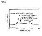
- the present inventors discovered that a method of quantitatively estimating the volume percentage of the amorphous phase by crushing the thin strip cast alloy and obtaining the quantity of heat generated during crystallization by a thermal analysis was a simple but highly accurate method. Thus, the present inventors decided to adopt such a method.
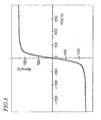
- the alloy may be regarded as including a greater volume percentage of amorphous phase. More specifically, if the alloy yet to be subjected to the heating/crystallizing process has a coercivity H cJ of 10 kA/m or less, then a magnet powder to be obtained subsequently by the heating/crystallizing process exhibits good magnetic properties. Thus, the present inventors decided that the coercivity H cJ be preferably 10 kA/m or less.
- Respective materials were mixed in such a manner as to obtain raw alloys having various compositions as represented by Nos. 1 through 11 in the following Table 1. Then, the raw alloys were subjected to a strip casting process under the casting conditions shown in Table 1. Subsequently, each of the resultant alloys was pulverized to obtain 20 g of powder that had been sieved to sizes of 150 ⁇ m or less. In this manner, alloy powders to be evaluated (or sample powders) were obtained. These alloy powders to be evaluated were subjected to a thermal analysis and magnetic property evaluations. The thermal analysis (i.e., measurement of the quantity of heat generated during crystallization) was carried out using a differential scanning calorimeter (DSC).
- DSC differential scanning calorimeter
Landscapes
- Chemical & Material Sciences (AREA)
- Engineering & Computer Science (AREA)
- Crystallography & Structural Chemistry (AREA)
- Inorganic Chemistry (AREA)
- Nanotechnology (AREA)
- Mechanical Engineering (AREA)
- Power Engineering (AREA)
- Composite Materials (AREA)
- Materials Engineering (AREA)
- Metallurgy (AREA)
- Organic Chemistry (AREA)
- Continuous Casting (AREA)
Applications Claiming Priority (2)
| Application Number | Priority Date | Filing Date | Title |
|---|---|---|---|
| JP2000307671 | 2000-10-06 | ||
| EP01967835A EP1338359B1 (de) | 2000-10-06 | 2001-09-25 | Verfahren zur herstellung einer rohlegierung durch bandgiessen für dauermagnete aus nanoverbundwerkstoff |
Related Parent Applications (2)
| Application Number | Title | Priority Date | Filing Date |
|---|---|---|---|
| EP01967835A Division EP1338359B1 (de) | 2000-10-06 | 2001-09-25 | Verfahren zur herstellung einer rohlegierung durch bandgiessen für dauermagnete aus nanoverbundwerkstoff |
| EP01967835.8 Division | 2001-09-25 |
Publications (3)
| Publication Number | Publication Date |
|---|---|
| EP1880782A2 true EP1880782A2 (de) | 2008-01-23 |
| EP1880782A3 EP1880782A3 (de) | 2013-04-17 |
| EP1880782B1 EP1880782B1 (de) | 2015-01-07 |
Family
ID=18788141
Family Applications (2)
| Application Number | Title | Priority Date | Filing Date |
|---|---|---|---|
| EP01967835A Expired - Lifetime EP1338359B1 (de) | 2000-10-06 | 2001-09-25 | Verfahren zur herstellung einer rohlegierung durch bandgiessen für dauermagnete aus nanoverbundwerkstoff |
| EP07015643.5A Expired - Lifetime EP1880782B1 (de) | 2000-10-06 | 2001-09-25 | Verfahren zur Bewertung einer Rohlegierung für einen Magneten |
Family Applications Before (1)
| Application Number | Title | Priority Date | Filing Date |
|---|---|---|---|
| EP01967835A Expired - Lifetime EP1338359B1 (de) | 2000-10-06 | 2001-09-25 | Verfahren zur herstellung einer rohlegierung durch bandgiessen für dauermagnete aus nanoverbundwerkstoff |
Country Status (7)
| Country | Link |
|---|---|
| US (2) | US7004228B2 (de) |
| EP (2) | EP1338359B1 (de) |
| JP (1) | JP4787459B2 (de) |
| CN (2) | CN100478687C (de) |
| AU (1) | AU2001288123A1 (de) |
| DE (1) | DE60131561T2 (de) |
| WO (1) | WO2002030595A1 (de) |
Families Citing this family (46)
| Publication number | Priority date | Publication date | Assignee | Title |
|---|---|---|---|---|
| JP3602120B2 (ja) * | 2002-08-08 | 2004-12-15 | 株式会社Neomax | ナノコンポジット磁石用急冷合金の製造方法 |
| KR101045696B1 (ko) * | 2002-10-17 | 2011-06-30 | 히타치 긴조쿠 가부시키가이샤 | 나노컴포지트 자석 및 그 제조방법 |
| CN1705761B (zh) * | 2002-10-25 | 2010-05-12 | 昭和电工株式会社 | 包含稀土元素的合金,其生产方法,磁致伸缩器件,以及磁性冷冻剂材料 |
| US7371292B2 (en) * | 2002-11-12 | 2008-05-13 | Nissan Motor Co., Ltd. | Nd-Fe-B type anisotropic exchange spring magnet and method of producing the same |
| JP4179973B2 (ja) * | 2003-11-18 | 2008-11-12 | Tdk株式会社 | 焼結磁石の製造方法 |
| US9022906B1 (en) | 2011-12-22 | 2015-05-05 | Preston Nelson | Top-loading adjustable weight kettlebell system |
| TWI268289B (en) * | 2004-05-28 | 2006-12-11 | Tsung-Shune Chin | Ternary and multi-nary iron-based bulk glassy alloys and nanocrystalline alloys |
| CN1297994C (zh) * | 2004-11-26 | 2007-01-31 | 中国兵器工业第五二研究所 | 无须磁场处理获取特殊矩形比纳米晶软磁材料的方法 |
| US9051630B2 (en) * | 2005-02-24 | 2015-06-09 | University Of Virginia Patent Foundation | Amorphous steel composites with enhanced strengths, elastic properties and ductilities |
| JP4603426B2 (ja) * | 2005-06-10 | 2010-12-22 | 株式会社アルバック | 真空溶解鋳造装置の冷却促進機構 |
| US20090035170A1 (en) * | 2007-02-05 | 2009-02-05 | Showa Denko K.K. | R-t-b type alloy and production method thereof, fine powder for r-t-b type rare earth permanent magnet, and r-t-b type rare earth permanent magnet |
| CN100432268C (zh) * | 2007-02-09 | 2008-11-12 | 上海大学 | 一种Fe基大块非晶合金及其制备方法 |
| CN100432271C (zh) * | 2007-02-09 | 2008-11-12 | 上海大学 | 一种具有硬磁性的铁基大块非晶合金及其制备方法 |
| JP5274781B2 (ja) * | 2007-03-22 | 2013-08-28 | 昭和電工株式会社 | R−t−b系合金及びr−t−b系合金の製造方法、r−t−b系希土類永久磁石用微粉、r−t−b系希土類永久磁石 |
| CN100465323C (zh) * | 2007-07-13 | 2009-03-04 | 上海大学 | 一种纳米晶复合永磁合金及其制备方法 |
| JPWO2009075351A1 (ja) * | 2007-12-13 | 2011-04-28 | 昭和電工株式会社 | R−t−b系合金及びr−t−b系合金の製造方法、r−t−b系希土類永久磁石用微粉、r−t−b系希土類永久磁石 |
| CN101509106B (zh) * | 2008-02-20 | 2010-06-30 | 吴更生 | 一种铁基非晶态合金材料及其制备方法 |
| EP2740551B1 (de) * | 2011-08-03 | 2019-10-16 | Santoku Corporation | Legierungsflocken als ausgangsmaterial für gesinterten seltenerdmagneten |
| JP5376098B2 (ja) * | 2011-11-14 | 2013-12-25 | Jfeスチール株式会社 | 金属薄帯の製造方法および製造設備 |
| WO2013103132A1 (ja) * | 2012-01-04 | 2013-07-11 | トヨタ自動車株式会社 | 希土類ナノコンポジット磁石 |
| CN102909329B (zh) * | 2012-11-05 | 2014-05-14 | 江苏锦宏有色金属材料有限公司 | 多喷嘴用非晶合金带分带器 |
| CN103805825B (zh) * | 2012-11-08 | 2016-04-06 | 沈阳中北真空科技有限公司 | 稀土永磁合金真空感应熔炼速凝设备 |
| CN103077796B (zh) * | 2013-02-06 | 2015-06-17 | 江苏南方永磁科技有限公司 | 一种耐蚀钕铁硼永磁材料及其制备方法 |
| US10464132B2 (en) | 2013-05-24 | 2019-11-05 | Toyota Jidosha Kabushiki Kaisha | Permanent magnet source powder fabrication method, permanent magnet fabrication method, and permanent magnet raw material powder inspection method |
| WO2014205002A2 (en) | 2013-06-17 | 2014-12-24 | Miha Zakotnik | Magnet recycling to create nd-fe-b magnets with improved or restored magnetic performance |
| CN103469118B (zh) * | 2013-07-20 | 2016-01-20 | 南通万宝实业有限公司 | 节能电机的非晶铁合金铁芯及其制备方法 |
| US9336932B1 (en) | 2014-08-15 | 2016-05-10 | Urban Mining Company | Grain boundary engineering |
| CN105543727B (zh) * | 2015-12-11 | 2017-11-21 | 江西大有科技有限公司 | 应用于防盗传感的非晶合金磁条及其制备方法 |
| CN107262688B (zh) * | 2016-04-08 | 2019-04-02 | 沈阳中北真空技术有限公司 | 一种带二次冷却的真空熔炼速凝设备及速凝合金制造方法 |
| CN106270520A (zh) * | 2016-09-29 | 2017-01-04 | 柳州增程材料科技有限公司 | 高强度高模量3d打印材料的制备方法 |
| CN106270541A (zh) * | 2016-09-29 | 2017-01-04 | 柳州增程材料科技有限公司 | 高强度增材制造材料的加工方法 |
| CN106392087A (zh) * | 2016-09-29 | 2017-02-15 | 柳州增程材料科技有限公司 | 一种高强度3d打印金属材料的制备方法 |
| CN106216698A (zh) * | 2016-09-29 | 2016-12-14 | 柳州增程材料科技有限公司 | 一种3d打印用合金粉末的制备工艺 |
| CN106166616A (zh) * | 2016-09-29 | 2016-11-30 | 柳州增程材料科技有限公司 | 一种3d打印用金属粉末的制备方法 |
| CN106392086A (zh) * | 2016-09-30 | 2017-02-15 | 柳州增程材料科技有限公司 | 一种铝镁合金粉末的制备工艺 |
| CN106216700A (zh) * | 2016-09-30 | 2016-12-14 | 柳州增程材料科技有限公司 | 一种变速箱用铝镁合金粉末的制备工艺 |
| CN107045910B (zh) * | 2017-03-27 | 2019-02-19 | 河北工业大学 | 一种Nd-Fe-B薄带磁体及其制备方法 |
| CN107377910B (zh) * | 2017-08-05 | 2019-05-28 | 江苏轩辕特种材料科技有限公司 | 一种铁硅硼合金带材防氧化单辊快淬工艺 |
| JP6460276B1 (ja) * | 2017-08-07 | 2019-01-30 | Tdk株式会社 | 軟磁性合金および磁性部品 |
| CN109248994B (zh) * | 2017-08-19 | 2021-05-25 | 福建省长汀金龙稀土有限公司 | 一种薄带的铸造装置及薄带的铸造方法 |
| CN108531834B (zh) * | 2018-04-17 | 2019-12-06 | 华中科技大学 | 一种耐磨耐蚀高铬铁基非晶合金及其制备方法 |
| CN109014222A (zh) * | 2018-07-19 | 2018-12-18 | 芜湖君华材料有限公司 | 一种非金合金带材收集切碎设备 |
| CN108788036A (zh) * | 2018-07-20 | 2018-11-13 | 芜湖君华材料有限公司 | 一种非晶合金材料快淬切碎系统 |
| CN108907208A (zh) * | 2018-07-21 | 2018-11-30 | 芜湖君华材料有限公司 | 一种非晶合金磁性粉末生产系统 |
| CN113035559B (zh) * | 2021-04-01 | 2022-07-08 | 包头市科锐微磁新材料有限责任公司 | 一种高性能钕铁硼各向同性磁粉的制备方法 |
| CN113512685B (zh) * | 2021-04-22 | 2023-03-24 | 北京中磁新材科技有限公司 | Fe基磁性合金及其制备方法 |
Family Cites Families (77)
| Publication number | Priority date | Publication date | Assignee | Title |
|---|---|---|---|---|
| JPS5594151A (en) * | 1979-01-12 | 1980-07-17 | Hitachi Ltd | Method of measuring amorphous state of amorphous ferromagnetic substance |
| CA1316375C (en) * | 1982-08-21 | 1993-04-20 | Masato Sagawa | Magnetic materials and permanent magnets |
| JPS5946008A (ja) | 1982-08-21 | 1984-03-15 | Sumitomo Special Metals Co Ltd | 永久磁石 |
| EP0108474B2 (de) * | 1982-09-03 | 1995-06-21 | General Motors Corporation | RE-TM-B Legierungen, deren Herstellung und permanent Magnete die solche Legierungen enthalten |
| US4851058A (en) * | 1982-09-03 | 1989-07-25 | General Motors Corporation | High energy product rare earth-iron magnet alloys |
| US5174362A (en) * | 1982-09-03 | 1992-12-29 | General Motors Corporation | High-energy product rare earth-iron magnet alloys |
| JPS609852A (ja) | 1983-06-24 | 1985-01-18 | ゼネラル・モ−タ−ズ・コ−ポレ−シヨン | 高エネルギ−積の稀土類−鉄磁石合金 |
| JPS61140350A (ja) | 1984-12-13 | 1986-06-27 | Toyota Central Res & Dev Lab Inc | 金属薄帯の製造装置 |
| EP0242187B1 (de) * | 1986-04-15 | 1992-06-03 | TDK Corporation | Dauermagnet und Verfahren zu seiner Herstellung |
| JP2727506B2 (ja) | 1986-04-15 | 1998-03-11 | ティーディーケイ株式会社 | 永久磁石およびその製造方法 |
| JP2727505B2 (ja) | 1986-04-15 | 1998-03-11 | ティーディーケイ株式会社 | 永久磁石およびその製造方法 |
| EP0264153B1 (de) * | 1986-10-10 | 1992-03-18 | Koninklijke Philips Electronics N.V. | Magnetisches Material aus Eisen, Bor und Seltenerdmetall |
| JPS647501U (de) | 1987-07-03 | 1989-01-17 | ||
| JPS647502U (de) | 1987-07-03 | 1989-01-17 | ||
| JPH01103805A (ja) * | 1987-07-30 | 1989-04-20 | Tdk Corp | 永久磁石 |
| US5022939A (en) * | 1987-07-30 | 1991-06-11 | Tdk Corporation | Permanent magnets |
| JPH01100242A (ja) | 1987-10-13 | 1989-04-18 | Tdk Corp | 永久磁石材料 |
| JPH02247A (ja) | 1987-12-07 | 1990-01-05 | Heinz Bereuter | 少なくとも一部がパーフルオロアミノカルボン酸及び/又はパーフルオロアミドカルボン酸の新規塩類又はアミン類、及びその利用 |
| US4919732A (en) * | 1988-07-25 | 1990-04-24 | Kubota Ltd. | Iron-neodymium-boron permanent magnet alloys which contain dispersed phases and have been prepared using a rapid solidification process |
| JP2843379B2 (ja) * | 1988-10-04 | 1999-01-06 | 日立金属株式会社 | 等方性耐熱ボンド磁石およびその製造方法ならびにそれを用いる磁粉、それを用いたpm型モータ |
| JPH02179803A (ja) | 1988-12-28 | 1990-07-12 | Nippon Steel Corp | Nd系永久磁石用フレーク製造用注湯容器 |
| JPH02247307A (ja) | 1989-03-17 | 1990-10-03 | Nippon Steel Corp | Nd合金フレーク製造方法 |
| JPH02247308A (ja) | 1989-03-17 | 1990-10-03 | Nippon Steel Corp | Nd合金フレーク製造用冷却ドラムの外周面調整方法及び装置 |
| JPH02247310A (ja) | 1989-03-17 | 1990-10-03 | Nippon Steel Corp | 雰囲気型超急冷装置の防爆安全扉 |
| JPH02247306A (ja) | 1989-03-17 | 1990-10-03 | Nippon Steel Corp | Nd合金注湯ノズルの地金除去装置 |
| JPH02247305A (ja) | 1989-03-17 | 1990-10-03 | Nippon Steel Corp | Nd合金フレーク製造時の雰囲気圧制御方法 |
| JPH02247309A (ja) | 1989-03-17 | 1990-10-03 | Nippon Steel Corp | 超急冷フレーク用温度測定装置 |
| JPH02298003A (ja) * | 1989-05-12 | 1990-12-10 | Fuji Elelctrochem Co Ltd | 希土類永久磁石の製造方法 |
| JPH0831386B2 (ja) | 1990-03-09 | 1996-03-27 | 富士電気化学株式会社 | 異方性希土類永久磁石の製造方法 |
| JPH0831385B2 (ja) | 1990-03-09 | 1996-03-27 | 富士電気化学株式会社 | 異方性希土類永久磁石の製造方法 |
| JP3502107B2 (ja) * | 1991-08-29 | 2004-03-02 | Tdk株式会社 | 永久磁石材料の製造方法 |
| DE69405817T2 (de) | 1993-06-14 | 1998-01-15 | Santoku Metal Ind | Verfahren zur Herstellung eines Dauermagneten aus Seltenerdmetall, Bor und Eisen |
| JP3299630B2 (ja) | 1993-06-14 | 2002-07-08 | 株式会社三徳 | 永久磁石の製造法 |
| JP3304175B2 (ja) | 1993-10-20 | 2002-07-22 | エフ・ディ−・ケイ株式会社 | 希土類急冷粉体の製造方法、希土類急冷粉体、ボンド磁石の製造方法、およびボンド磁石 |
| JPH07166206A (ja) | 1993-12-10 | 1995-06-27 | Sumitomo Special Metals Co Ltd | 永久磁石合金粉末とその製造方法 |
| JP3311907B2 (ja) | 1994-10-06 | 2002-08-05 | 増本 健 | 永久磁石材料、永久磁石及び永久磁石の製造方法 |
| JP3777199B2 (ja) | 1994-12-09 | 2006-05-24 | 株式会社Neomax | 高性能R−Fe−B系永久磁石材料の製造方法 |
| US5666635A (en) * | 1994-10-07 | 1997-09-09 | Sumitomo Special Metals Co., Ltd. | Fabrication methods for R-Fe-B permanent magnets |
| JP3535253B2 (ja) | 1995-02-23 | 2004-06-07 | 住友特殊金属株式会社 | R−Fe−B系永久磁石用鋳片の製造方法 |
| JP3641021B2 (ja) * | 1995-04-01 | 2005-04-20 | 株式会社Neomax | 高保磁力鉄基永久磁石及びボンド磁石 |
| JP3845461B2 (ja) * | 1995-04-06 | 2006-11-15 | 株式会社Neomax | ボンド磁石用永久磁石合金粉末の製造方法及びその装置 |
| US5800635A (en) * | 1995-06-15 | 1998-09-01 | Alliedsignal Inc. | Method of achieving a controlled step change in the magnetization loop of amorphous alloys |
| JP3201944B2 (ja) | 1995-12-04 | 2001-08-27 | 株式会社三徳 | 希土類金属含有合金の製造システム |
| JPH09155513A (ja) | 1995-12-04 | 1997-06-17 | Santoku Kinzoku Kogyo Kk | ストリップキャスト用タンディッシュ |
| US6022424A (en) * | 1996-04-09 | 2000-02-08 | Lockheed Martin Idaho Technologies Company | Atomization methods for forming magnet powders |
| US5725792A (en) * | 1996-04-10 | 1998-03-10 | Magnequench International, Inc. | Bonded magnet with low losses and easy saturation |
| JPH1088294A (ja) | 1996-09-12 | 1998-04-07 | Alps Electric Co Ltd | 硬磁性材料 |
| WO1998036428A1 (en) | 1997-02-14 | 1998-08-20 | Sumitomo Special Metals Co., Ltd. | Thin plate magnet having microcrystalline structure |
| EP0867897B1 (de) * | 1997-03-25 | 2003-11-26 | Alps Electric Co., Ltd. | Auf Fe basierte hartmagnetische Legierung mit einer supergekühlter Spanne |
| JP3488358B2 (ja) | 1997-03-27 | 2004-01-19 | 住友特殊金属株式会社 | 微細結晶永久磁石合金及び永久磁石粉末の製造方法 |
| JPH10317109A (ja) | 1997-05-22 | 1998-12-02 | Sumitomo Special Metals Co Ltd | 薄肉永久磁石の製造方法 |
| US5905424A (en) * | 1997-08-04 | 1999-05-18 | Magnequench International, Inc. | Bonded magnet made from gas atomized powders of rare earth alloy |
| JPH1171646A (ja) | 1997-08-29 | 1999-03-16 | Alps Electric Co Ltd | スピーカ |
| EP0898287B1 (de) * | 1997-08-22 | 2003-05-21 | Alps Electric Co., Ltd. | Hartmagnetische Legierung mit supergekühlter Schmelzregion,gesintertes Produkt davon und Anwendungen |
| US6332933B1 (en) | 1997-10-22 | 2001-12-25 | Santoku Corporation | Iron-rare earth-boron-refractory metal magnetic nanocomposites |
| US6183572B1 (en) * | 1997-12-30 | 2001-02-06 | Magnequench International, Inc. | Isotropic rare earth material of high intrinsic induction |
| JPH11323509A (ja) | 1998-05-15 | 1999-11-26 | Alps Electric Co Ltd | 硬磁性合金圧密成形体およびその製造方法 |
| JP3981788B2 (ja) | 1998-06-24 | 2007-09-26 | 株式会社アルバック | 希土類元素含有合金の鋳造装置および製造方法 |
| JP3901875B2 (ja) | 1998-06-24 | 2007-04-04 | 株式会社アルバック | タンディッシュ、およびそのタンディッシュを用いた希土類元素含有合金の製造方法と、そのタンディッシュを備えた希土類元素含有合金の製造装置 |
| TW493185B (en) * | 1998-07-13 | 2002-07-01 | Santoku Inc | High performance iron-rare earth-boron-refractory-cobalt nanocomposites |
| DE69940976D1 (de) * | 1998-10-30 | 2009-07-23 | Santoku Corp | Sm (Co, Fe, Cu, Zr, C) ZUSAMMENSETZUNGEN UND VERFAHREN ZU DEREN HERSTELLUNG |
| JP3604308B2 (ja) * | 1998-12-07 | 2004-12-22 | 株式会社Neomax | ナノコンポジット磁石用原料合金、その粉末および製造方法、ならびにナノコンポジット磁石粉末および磁石の製造方法 |
| US6302972B1 (en) * | 1998-12-07 | 2001-10-16 | Sumitomo Special Metals Co., Ltd | Nanocomposite magnet material and method for producing nanocomposite magnet |
| US6302939B1 (en) | 1999-02-01 | 2001-10-16 | Magnequench International, Inc. | Rare earth permanent magnet and method for making same |
| US6524399B1 (en) | 1999-03-05 | 2003-02-25 | Pioneer Metals And Technology, Inc. | Magnetic material |
| JP3712595B2 (ja) * | 1999-06-08 | 2005-11-02 | 信越化学工業株式会社 | 永久磁石用合金薄帯および焼結永久磁石 |
| DE60031914T8 (de) | 1999-06-11 | 2007-10-31 | Seiko Epson Corp. | Magnetpulver und isotroper Verbundmagnet |
| JP2001052911A (ja) | 1999-08-11 | 2001-02-23 | Seiko Epson Corp | 磁石材料の製造方法、薄帯状磁石材料、磁石粉末およびボンド磁石 |
| JP3365628B2 (ja) | 1999-12-21 | 2003-01-14 | 住友特殊金属株式会社 | 鉄基合金永久磁石粉末およびその製造方法 |
| JP2001226753A (ja) | 2000-02-10 | 2001-08-21 | Sumitomo Special Metals Co Ltd | 鉄基合金軟磁性材料およびその製造方法 |
| JP3886317B2 (ja) * | 2000-03-10 | 2007-02-28 | 独立行政法人科学技術振興機構 | 高ガラス形成能を有する鉄基永久磁石合金 |
| WO2001091139A1 (en) * | 2000-05-24 | 2001-11-29 | Sumitomo Special Metals Co., Ltd. | Permanent magnet including multiple ferromagnetic phases and method for producing the magnet |
| JP2002080921A (ja) * | 2000-09-07 | 2002-03-22 | Sumitomo Special Metals Co Ltd | 鉄基希土類合金磁石用原料合金およびその製造方法 |
| US6790296B2 (en) * | 2000-11-13 | 2004-09-14 | Neomax Co., Ltd. | Nanocomposite magnet and method for producing same |
| DE60228198D1 (de) * | 2001-02-07 | 2008-09-25 | Hitachi Metals Ltd | Verfahren zur herstellung einer metalllegierung für einen seltenerdmagneten auf eisenbasis |
| JP4023138B2 (ja) * | 2001-02-07 | 2007-12-19 | 日立金属株式会社 | 鉄基希土類合金粉末および鉄基希土類合金粉末を含むコンパウンドならびにそれを用いた永久磁石 |
| KR101045696B1 (ko) * | 2002-10-17 | 2011-06-30 | 히타치 긴조쿠 가부시키가이샤 | 나노컴포지트 자석 및 그 제조방법 |
-
2001
- 2001-09-25 CN CNB2005100511775A patent/CN100478687C/zh not_active Expired - Fee Related
- 2001-09-25 US US10/381,412 patent/US7004228B2/en not_active Expired - Lifetime
- 2001-09-25 WO PCT/JP2001/008317 patent/WO2002030595A1/ja not_active Ceased
- 2001-09-25 DE DE60131561T patent/DE60131561T2/de not_active Expired - Lifetime
- 2001-09-25 EP EP01967835A patent/EP1338359B1/de not_active Expired - Lifetime
- 2001-09-25 AU AU2001288123A patent/AU2001288123A1/en not_active Abandoned
- 2001-09-25 CN CNB018121764A patent/CN1228158C/zh not_active Expired - Fee Related
- 2001-09-25 EP EP07015643.5A patent/EP1880782B1/de not_active Expired - Lifetime
- 2001-09-25 JP JP2002534022A patent/JP4787459B2/ja not_active Expired - Fee Related
-
2005
- 2005-11-28 US US11/288,710 patent/US7547365B2/en not_active Expired - Fee Related
Also Published As
| Publication number | Publication date |
|---|---|
| JP4787459B2 (ja) | 2011-10-05 |
| CN100478687C (zh) | 2009-04-15 |
| EP1338359B1 (de) | 2007-11-21 |
| AU2001288123A1 (en) | 2002-04-22 |
| EP1338359A1 (de) | 2003-08-27 |
| EP1338359A4 (de) | 2006-06-07 |
| WO2002030595A1 (en) | 2002-04-18 |
| JPWO2002030595A1 (ja) | 2004-02-19 |
| DE60131561T2 (de) | 2008-03-06 |
| CN1440317A (zh) | 2003-09-03 |
| DE60131561D1 (de) | 2008-01-03 |
| US20060081308A1 (en) | 2006-04-20 |
| CN1228158C (zh) | 2005-11-23 |
| CN1657936A (zh) | 2005-08-24 |
| US20030183305A1 (en) | 2003-10-02 |
| EP1880782B1 (de) | 2015-01-07 |
| US7547365B2 (en) | 2009-06-16 |
| US7004228B2 (en) | 2006-02-28 |
| EP1880782A3 (de) | 2013-04-17 |
Similar Documents
| Publication | Publication Date | Title |
|---|---|---|
| EP1880782B1 (de) | Verfahren zur Bewertung einer Rohlegierung für einen Magneten | |
| US6695929B2 (en) | Method of making material alloy for iron-based rare earth magnet | |
| US7160398B2 (en) | Method of making rapidly solidified alloy for magnet | |
| US7208097B2 (en) | Iron-based rare earth alloy nanocomposite magnet and method for producing the same | |
| EP1446816B1 (de) | Nanozusammensetzungsmagnet | |
| EP1403884B1 (de) | Rasch erstarrte Legierung für Herstellung eines anisotropen Magnetpulvers und eines Verbundmagnets | |
| US7842140B2 (en) | Iron-based rare-earth nanocomposite magnet and method for producing the magnet | |
| US8961868B2 (en) | Nanocomposite bulk magnet and process for producing same | |
| EP1552537B1 (de) | Nanokomposit-magnet und herstellungsverfahren | |
| US20100219922A1 (en) | Nano-composite magnet, quenched alloy for nano-composite magnet, and method for producing them and method for distinguishing them | |
| EP1762632B1 (de) | Seltene erden enthaltender nanokomposit-magnet auf eisenbasis und verfahren zu dessen herstellung | |
| US7958929B2 (en) | Apparatus for producing alloy and rare earth element alloy | |
| JP4120253B2 (ja) | ナノコンポジット磁石用急冷合金およびその製造方法 | |
| US20090129966A1 (en) | Iron-based rare-earth-containing nanocomposite magnet and process for producing the same |
Legal Events
| Date | Code | Title | Description |
|---|---|---|---|
| PUAI | Public reference made under article 153(3) epc to a published international application that has entered the european phase |
Free format text: ORIGINAL CODE: 0009012 |
|
| AC | Divisional application: reference to earlier application |
Ref document number: 1338359 Country of ref document: EP Kind code of ref document: P |
|
| AK | Designated contracting states |
Kind code of ref document: A2 Designated state(s): AT DE FR GB NL |
|
| RIN1 | Information on inventor provided before grant (corrected) |
Inventor name: HIROSAWA, SATOSHI Inventor name: KANEKIYO, HIROKAZU Inventor name: MURAKAMI, RYO |
|
| RAP1 | Party data changed (applicant data changed or rights of an application transferred) |
Owner name: SANTOKU CORPORATION Owner name: HITACHI METALS, LTD. |
|
| REG | Reference to a national code |
Ref country code: DE Ref legal event code: R079 Ref document number: 60149191 Country of ref document: DE Free format text: PREVIOUS MAIN CLASS: B22D0011060000 Ipc: C22C0045020000 |
|
| PUAL | Search report despatched |
Free format text: ORIGINAL CODE: 0009013 |
|
| AK | Designated contracting states |
Kind code of ref document: A3 Designated state(s): AT DE FR GB NL |
|
| RIC1 | Information provided on ipc code assigned before grant |
Ipc: C21D 6/00 20060101ALI20130312BHEP Ipc: C22C 45/02 20060101AFI20130312BHEP |
|
| 17P | Request for examination filed |
Effective date: 20130906 |
|
| RBV | Designated contracting states (corrected) |
Designated state(s): AT DE FR GB NL |
|
| 17Q | First examination report despatched |
Effective date: 20131009 |
|
| AKX | Designation fees paid |
Designated state(s): AT DE FR GB NL |
|
| GRAP | Despatch of communication of intention to grant a patent |
Free format text: ORIGINAL CODE: EPIDOSNIGR1 |
|
| INTG | Intention to grant announced |
Effective date: 20140723 |
|
| GRAS | Grant fee paid |
Free format text: ORIGINAL CODE: EPIDOSNIGR3 |
|
| GRAA | (expected) grant |
Free format text: ORIGINAL CODE: 0009210 |
|
| AC | Divisional application: reference to earlier application |
Ref document number: 1338359 Country of ref document: EP Kind code of ref document: P |
|
| AK | Designated contracting states |
Kind code of ref document: B1 Designated state(s): AT DE FR GB NL |
|
| REG | Reference to a national code |
Ref country code: GB Ref legal event code: FG4D |
|
| REG | Reference to a national code |
Ref country code: AT Ref legal event code: REF Ref document number: 705804 Country of ref document: AT Kind code of ref document: T Effective date: 20150215 |
|
| REG | Reference to a national code |
Ref country code: DE Ref legal event code: R096 Ref document number: 60149191 Country of ref document: DE Effective date: 20150226 |
|
| REG | Reference to a national code |
Ref country code: NL Ref legal event code: VDEP Effective date: 20150107 |
|
| REG | Reference to a national code |
Ref country code: AT Ref legal event code: MK05 Ref document number: 705804 Country of ref document: AT Kind code of ref document: T Effective date: 20150107 |
|
| PG25 | Lapsed in a contracting state [announced via postgrant information from national office to epo] |
Ref country code: AT Free format text: LAPSE BECAUSE OF FAILURE TO SUBMIT A TRANSLATION OF THE DESCRIPTION OR TO PAY THE FEE WITHIN THE PRESCRIBED TIME-LIMIT Effective date: 20150107 Ref country code: NL Free format text: LAPSE BECAUSE OF FAILURE TO SUBMIT A TRANSLATION OF THE DESCRIPTION OR TO PAY THE FEE WITHIN THE PRESCRIBED TIME-LIMIT Effective date: 20150107 |
|
| REG | Reference to a national code |
Ref country code: DE Ref legal event code: R097 Ref document number: 60149191 Country of ref document: DE |
|
| PLBE | No opposition filed within time limit |
Free format text: ORIGINAL CODE: 0009261 |
|
| STAA | Information on the status of an ep patent application or granted ep patent |
Free format text: STATUS: NO OPPOSITION FILED WITHIN TIME LIMIT |
|
| 26N | No opposition filed |
Effective date: 20151008 |
|
| GBPC | Gb: european patent ceased through non-payment of renewal fee |
Effective date: 20150925 |
|
| REG | Reference to a national code |
Ref country code: FR Ref legal event code: ST Effective date: 20160531 |
|
| PG25 | Lapsed in a contracting state [announced via postgrant information from national office to epo] |
Ref country code: GB Free format text: LAPSE BECAUSE OF NON-PAYMENT OF DUE FEES Effective date: 20150925 |
|
| PG25 | Lapsed in a contracting state [announced via postgrant information from national office to epo] |
Ref country code: FR Free format text: LAPSE BECAUSE OF NON-PAYMENT OF DUE FEES Effective date: 20150930 |
|
| PGFP | Annual fee paid to national office [announced via postgrant information from national office to epo] |
Ref country code: DE Payment date: 20180911 Year of fee payment: 18 |
|
| REG | Reference to a national code |
Ref country code: DE Ref legal event code: R119 Ref document number: 60149191 Country of ref document: DE |
|
| PG25 | Lapsed in a contracting state [announced via postgrant information from national office to epo] |
Ref country code: DE Free format text: LAPSE BECAUSE OF NON-PAYMENT OF DUE FEES Effective date: 20200401 |