EP1882575A1 - Moule de fabrication de disque, procédé de fabrication idoine et pièces de moule - Google Patents
Moule de fabrication de disque, procédé de fabrication idoine et pièces de moule Download PDFInfo
- Publication number
- EP1882575A1 EP1882575A1 EP06746542A EP06746542A EP1882575A1 EP 1882575 A1 EP1882575 A1 EP 1882575A1 EP 06746542 A EP06746542 A EP 06746542A EP 06746542 A EP06746542 A EP 06746542A EP 1882575 A1 EP1882575 A1 EP 1882575A1
- Authority
- EP
- European Patent Office
- Prior art keywords
- disc
- mold
- support plate
- cavity
- ring
- Prior art date
- Legal status (The legal status is an assumption and is not a legal conclusion. Google has not performed a legal analysis and makes no representation as to the accuracy of the status listed.)
- Withdrawn
Links
- 238000000465 moulding Methods 0.000 title claims abstract description 35
- 238000000034 method Methods 0.000 title claims description 7
- 238000004519 manufacturing process Methods 0.000 title claims description 4
- 238000005121 nitriding Methods 0.000 claims abstract description 25
- 239000000758 substrate Substances 0.000 abstract description 22
- 230000003247 decreasing effect Effects 0.000 abstract description 3
- 239000011347 resin Substances 0.000 description 14
- 229920005989 resin Polymers 0.000 description 14
- 238000002347 injection Methods 0.000 description 11
- 239000007924 injection Substances 0.000 description 11
- 230000002093 peripheral effect Effects 0.000 description 8
- 238000010438 heat treatment Methods 0.000 description 7
- 239000011248 coating agent Substances 0.000 description 4
- 238000000576 coating method Methods 0.000 description 4
- 238000004080 punching Methods 0.000 description 4
- 208000035212 Ring chromosome 19 syndrome Diseases 0.000 description 3
- 238000001816 cooling Methods 0.000 description 3
- 230000007423 decrease Effects 0.000 description 3
- 238000001746 injection moulding Methods 0.000 description 3
- 239000000203 mixture Substances 0.000 description 3
- XEEYBQQBJWHFJM-UHFFFAOYSA-N Iron Chemical compound [Fe] XEEYBQQBJWHFJM-UHFFFAOYSA-N 0.000 description 2
- 230000015572 biosynthetic process Effects 0.000 description 2
- 230000004048 modification Effects 0.000 description 2
- 238000012986 modification Methods 0.000 description 2
- 125000000129 anionic group Chemical group 0.000 description 1
- 230000000712 assembly Effects 0.000 description 1
- 238000000429 assembly Methods 0.000 description 1
- 238000007664 blowing Methods 0.000 description 1
- 125000002091 cationic group Chemical group 0.000 description 1
- 239000011247 coating layer Substances 0.000 description 1
- 230000000694 effects Effects 0.000 description 1
- 229910052742 iron Inorganic materials 0.000 description 1
- 239000010410 layer Substances 0.000 description 1
- 239000007769 metal material Substances 0.000 description 1
- 239000012778 molding material Substances 0.000 description 1
- 150000004767 nitrides Chemical class 0.000 description 1
- 230000003746 surface roughness Effects 0.000 description 1
- XLYOFNOQVPJJNP-UHFFFAOYSA-N water Substances O XLYOFNOQVPJJNP-UHFFFAOYSA-N 0.000 description 1
Images

Classifications
-
- B—PERFORMING OPERATIONS; TRANSPORTING
- B29—WORKING OF PLASTICS; WORKING OF SUBSTANCES IN A PLASTIC STATE IN GENERAL
- B29C—SHAPING OR JOINING OF PLASTICS; SHAPING OF MATERIAL IN A PLASTIC STATE, NOT OTHERWISE PROVIDED FOR; AFTER-TREATMENT OF THE SHAPED PRODUCTS, e.g. REPAIRING
- B29C45/00—Injection moulding, i.e. forcing the required volume of moulding material through a nozzle into a closed mould; Apparatus therefor
- B29C45/17—Component parts, details or accessories; Auxiliary operations
- B29C45/26—Moulds
-
- B—PERFORMING OPERATIONS; TRANSPORTING
- B29—WORKING OF PLASTICS; WORKING OF SUBSTANCES IN A PLASTIC STATE IN GENERAL
- B29C—SHAPING OR JOINING OF PLASTICS; SHAPING OF MATERIAL IN A PLASTIC STATE, NOT OTHERWISE PROVIDED FOR; AFTER-TREATMENT OF THE SHAPED PRODUCTS, e.g. REPAIRING
- B29C45/00—Injection moulding, i.e. forcing the required volume of moulding material through a nozzle into a closed mould; Apparatus therefor
- B29C45/17—Component parts, details or accessories; Auxiliary operations
- B29C45/26—Moulds
- B29C45/263—Moulds with mould wall parts provided with fine grooves or impressions, e.g. for record discs
-
- B—PERFORMING OPERATIONS; TRANSPORTING
- B29—WORKING OF PLASTICS; WORKING OF SUBSTANCES IN A PLASTIC STATE IN GENERAL
- B29C—SHAPING OR JOINING OF PLASTICS; SHAPING OF MATERIAL IN A PLASTIC STATE, NOT OTHERWISE PROVIDED FOR; AFTER-TREATMENT OF THE SHAPED PRODUCTS, e.g. REPAIRING
- B29C33/00—Moulds or cores; Details thereof or accessories therefor
- B29C33/38—Moulds or cores; Details thereof or accessories therefor characterised by the material or the manufacturing process
-
- B—PERFORMING OPERATIONS; TRANSPORTING
- B29—WORKING OF PLASTICS; WORKING OF SUBSTANCES IN A PLASTIC STATE IN GENERAL
- B29C—SHAPING OR JOINING OF PLASTICS; SHAPING OF MATERIAL IN A PLASTIC STATE, NOT OTHERWISE PROVIDED FOR; AFTER-TREATMENT OF THE SHAPED PRODUCTS, e.g. REPAIRING
- B29C33/00—Moulds or cores; Details thereof or accessories therefor
- B29C33/56—Coatings, e.g. enameled or galvanised; Releasing, lubricating or separating agents
-
- G—PHYSICS
- G11—INFORMATION STORAGE
- G11B—INFORMATION STORAGE BASED ON RELATIVE MOVEMENT BETWEEN RECORD CARRIER AND TRANSDUCER
- G11B7/00—Recording or reproducing by optical means, e.g. recording using a thermal beam of optical radiation by modifying optical properties or the physical structure, reproducing using an optical beam at lower power by sensing optical properties; Record carriers therefor
- G11B7/24—Record carriers characterised by shape, structure or physical properties, or by the selection of the material
- G11B7/26—Apparatus or processes specially adapted for the manufacture of record carriers
-
- G—PHYSICS
- G11—INFORMATION STORAGE
- G11B—INFORMATION STORAGE BASED ON RELATIVE MOVEMENT BETWEEN RECORD CARRIER AND TRANSDUCER
- G11B7/00—Recording or reproducing by optical means, e.g. recording using a thermal beam of optical radiation by modifying optical properties or the physical structure, reproducing using an optical beam at lower power by sensing optical properties; Record carriers therefor
- G11B7/24—Record carriers characterised by shape, structure or physical properties, or by the selection of the material
- G11B7/26—Apparatus or processes specially adapted for the manufacture of record carriers
- G11B7/263—Preparing and using a stamper, e.g. pressing or injection molding substrates
-
- B—PERFORMING OPERATIONS; TRANSPORTING
- B29—WORKING OF PLASTICS; WORKING OF SUBSTANCES IN A PLASTIC STATE IN GENERAL
- B29L—INDEXING SCHEME ASSOCIATED WITH SUBCLASS B29C, RELATING TO PARTICULAR ARTICLES
- B29L2017/00—Carriers for sound or information
Definitions
- the present invention relates to a disc-molding mold, a method for manufacturing the same, and a mold part.
- a molding machine such as an injection molding machine for molding disc substrates
- resin melted within a heating cylinder is charged into a cavity in a disc-molding mold, and is then cooled and solidified in the cavity so as to obtain a disc substrate.
- the above-mentioned injection molding machine includes the disc-molding mold consisting of a stationary-side mold assembly and a movable-side mold assembly; an injection apparatus for charging resin into a cavity; and a mold-clamping apparatus for bringing the movable-side mold assembly into contact with the stationary-side mold assembly and separating the movable-side mold assembly from the stationary-side mold assembly.
- the mold-clamping apparatus is operated so as to advance and retract the movable-side mold assembly to thereby close, clamp, and open the disc-molding mold.
- a cavity is formed between a disc plate of the stationary-side mold assembly and a disc plate of the movable-side mold assembly.
- the injection apparatus includes a heating cylinder; an injection nozzle attached to a front end of the heating cylinder; and a screw disposed in the heating cylinder so that the screw can rotate and can advance and retract.
- a metering step the screw is rotated, whereby resin is melted and stored in front of the screw, and the screw is retreated accordingly. During this period, the disc-molding mold is closed and clamped. Subsequently, in an injection step, the screw is advanced, whereby the resin accumulated in front of the screw is injected from the injection nozzle and charged into the cavity. In a cooling step, the resin in the cavity is cooled, and hole punching is performed, whereby a disc substrate is completed. Subsequently, the disc-molding mold is opened, and the disc substrate is removed therefrom.
- a stamper for forming fine projections on an information surface of the disc substrate is attached to the stationary disc plate, and a cavity ring for forming the outer circumferential edge of the disc substrate is attached to the movable disc plate, whereby the outer circumferential edge of the cavity is defined by the cavity ring.
- the cavity ring comes into contact with a butt ring provided on the stationary-side mold assembly and is caused to slide.
- the surface of the cavity ring may be subjected to nitriding in order to improve the wear resistance of the cavity ring.
- nitriding is generally performed in a high temperature range of 530 to 570°C. According, when nitriding is performed on a mold part, such as a cavity ring, which is thin and complicated in shape, the cavity ring or the like deforms, and its dimensional variation increases. Accordingly, accuracy of molded disc substrates decreases.
- An object of the present invention is to solve the above-mentioned problem in the conventional disc-molding mold and to provide a disc-molding mold which can improve the wear resistance of a mold part and can improve accuracy of disc substrates, as well as a method for manufacturing the same, and a mold part.
- a disc-molding mold of the present invention comprises a first mold including a first support plate and a first mirror-surface disc attached to the first support plate; and a second mold including a second support plate and a second mirror-surface disc attached to the second support plate.
- a sliding surface of a mold part disposed on one of the first and second molds is treated by means of low-temperature nitriding.
- a disc-molding mold comprises a first mold including a first support plate and a first mirror-surface disc attached to the first support plate; and a second mold including a second support plate and a second mirror-surface disc attached to the second support plate.
- a sliding surface of a mold part disposed on one of the first and second molds is treated by means of low-temperature nitriding.
- the mold part is treated by means of low-temperature nitriding, the wear resistance of the mold part can be improved.
- the treatment temperature is low, even when low-temperature nitriding is performed on a mold part which is complicated in shape, the mold part does not deform, and its dimensional variation can be decreased. As a result, accuracy of disc substrates can be improved.
- FIG. 1 is a sectional view of a disc-molding mold according to the embodiment of the present invention.
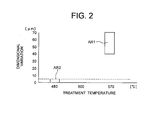
- FIG. 2 is a graph showing the relation between treatment temperature and dimensional variation of a cavity ring in the embodiment of the present invention.
- the horizontal axis represents treatment temperature
- the vertical axis represents dimensional variation.
- reference numeral 12 denotes a stationary-side mold assembly (first mold) attached to an unillustrated stationary platen via an attachment plate 13.
- the mold assembly 12 includes a base plate (first support plate) 15; a disc plate (first mirror-surface disc) 16 attached to the base plate 15; a locating ring 23 disposed within in the attachment plate 13 in such a manner as to face the stationary platen and adapted to position the base plate 15 with respect to the stationary platen; and a sprue bush 24 disposed within the base plate 15 to be adjacent to the locating ring 23.
- a die 28 is formed at the front end of the sprue bush 24 so that the die faces a cavity C.
- a sprue 26 is formed in the sprue bush 24 and communicates with the die 28. Resin (molding material) injected from an injection nozzle of an unillustrated injection apparatus passes through the sprue 26.
- the injection apparatus includes an unillustrated heating cylinder; an injection nozzle attached to the front end of the heating cylinder; and a screw disposed in the heating cylinder so that the screw can rotate and can advance and retract.
- An unillustrated stamper for forming fine projections on the information surface of an unillustrated disc substrate (molded product) is attached to the disc plate 16.
- a stamper-holding bush 14 for holding an inner circumferential edge of the stamper is disposed radially outward a front half portion of the sprue bush 24.
- an unillustrated air blow bush and the like are also disposed in the mold assembly 12.
- An annular butt ring 18 is attached to an outer circumferential edge of the disc plate 16 by use of bolts b1.
- An annular first peripheral ring 19 is disposed radially outward the disc plate 16 and the butt ring 18 and attached to the base plate 15.
- the stamper-holding bush 14, the disc plate 16, the butt ring 18, the first peripheral ring 19, the air blow bush, etc. consist mold parts of the mold assembly 12.
- reference numeral 32 denotes a movable-side mold assembly (second mold) attached to an unillustrated movable platen by use of unillustrated bolts.
- the mold assembly 32 includes a base plate 35; an intermediate plate 40 attached to the base plate 35 by use of bolts b2; a disc plate (second mirror-surface disc) 36 attached to the intermediate plate 40 by use of bolts b3; a cylinder (surrounding member) 44 which is disposed within the base plate 35 in such a manner as to face the movable platen and which is attached to the intermediate plate 40 by use of bolts b4; and a cut punch (punching member) 48 which is advanced and retreated along the cylinder 44 and which has a shape corresponding to the die 28.
- the base plate 35 and the intermediate plate 40 constitute a second support plate.
- An annular cavity ring 37 is disposed along an outer circumferential edge of the disc plate 36 and in opposition to the butt ring 18 such that the cavity ring 37 can move in relation to the disc plate 36.
- An annular second peripheral ring 38 is disposed radially outward the disc plate 36 and the cavity ring 37 and in opposition to the first peripheral ring 19 and is attached to the intermediate plate 40.
- the cavity ring 37 is attached to a rod 41 by use of bolts b5 such that it is disposed movably, via the rods 41, in relation to the intermediate plate 40.
- a spring (first urging member) 63 comes into contact with the rod 41 and urges the rod 41 and the cavity ring 37 toward the mold assembly 12.
- Reference numeral 39 denotes a cavity ring retainer attached to the second peripheral ring 38 by use of unillustrated bolts.
- the cavity ring retainer 39 is engaged with an outer circumferential edge of the cavity ring 37.
- the cavity ring 37 projects from the front end surface of the disc plate 36.
- the inner circumferential surface of the cavity ring 37 forms the outer circumferential edge of a disc substrate.
- a flange 51 formed integrally with the cut punch 48 is disposed within the cylinder 44 such that it can be advanced and retreated.
- a rear end 51a of the flange 51 is received by the cylinder 44.
- a cut-punch return spring (second urging member) 52 is disposed ahead of the flange 51. The cut-punch return spring 52 urges the flange 51 rearward.
- the mold assemblies 12 and 32 constitute a disc-molding mold; and an unillustrated mold-clamping apparatus is disposed in order to bring the mold assembly 32 into contact with the mold assembly 12 and separate the mold assembly 32 away from the mold assembly 12.
- the mold assembly 32 can be advanced and retreated through drive of a mold-clamping cylinder (drive section for mold clamping) of the mold-clamping apparatus, whereby the disc-molding mold can be closed, clamped, and opened.
- the above-described cavity C is formed between the disc plates 16 and 36.
- the cut punch 48 is advanced through drive of an unillustrated drive cylinder (drive section for punching).
- an ejector bush 62 for ejecting a disc substrate is disposed radially outward a front half portion of the cut punch 48.
- an air blow bush 47 for blowing compressed air against the disc substrate to thereby release the disc substrate from the disc plate 36 is disposed radially outward the ejector bush 62.
- an unillustrated ejector pin and the like component are disposed in the mold assembly 32.
- the disc plate 36, the cavity ring 37, the second peripheral ring 38, the rod 41, the air blow bush 47, the cut punch 48, the ejector bush 62, etc. consist mold parts of the mold assembly 32.
- First and second temperature control passages 93 and 94 are formed in the disc plates 16 and 36, respectively.
- a temperature control medium such as water, oil, or air, is caused to flow through the first and second temperature control passages 93 and 94, to thereby cool the disc plates 16 and 36.
- a metering step the screw is rotated, whereby resin is melted and accumulated in front of the screw, and the screw is retreated accordingly. During this period, the disc-molding mold is closed and clamped. Subsequently, in an injection step, the screw is advanced, whereby the resin accumulated in front of the screw is injected from the injection nozzle and charged into the cavity C. In a cooling step, the resin in the cavity C is cooled, and hole punching is performed, whereby a disc substrate is completed. Subsequently, the mold is opened, and the disc substrate is removed.
- the cavity ring 37 is accommodated in an annular groove formed by the disc plate 36 and the second peripheral ring 38 such that the cavity ring 37 can move in the axial direction, and is urged by the spring 63 toward the mold assembly 12. Accordingly, when the cavity ring 37 comes into contact with the butt ring 18 as a result of mold closing, after that point in time, the cavity ring 37 is retreated against the urging force of the spring 63. When the cavity ring 37 separates from the butt ring 18 as a result of mold opening, the cavity ring 37 is advanced by the urging force of the spring 63.
- the cavity ring 37 moves toward the mold assembly 12 and maintains the state in which the cavity ring 37 is in contact with the mold assembly 12.
- the cavity ring 37 comes into contact with the butt ring 18 and is caused to slide. Further, since the cavity ring 37 is caused to advance and retreat within the groove every time molding is performed, the outer and inner circumferential surfaces of the cavity ring 37 slide along the inner wall surface of the groove (the outer circumferential surface of the disc plate 36 and the inner circumferential surface of the second peripheral ring 38 within the groove).
- a surface of the cavity ring 37 (in the present embodiment, an contact surface of the cavity ring 37, which is a sliding surface that comes into contact with the butt ring 18 and slides thereon) is treated by means of low-temperature nitriding.
- the nitriding is performed in a bath of a molten-salt composition, which contains a cationic component (e.g., Na + and K + ) and an anionic component (e.g., CN - , CNO - , and CO 3 2- ), at a temperature not lower than 300°C but not higher than 500°C.
- a cationic component e.g., Na + and K +
- an anionic component e.g., CN - , CNO - , and CO 3 2-
- nitriding is performed for a predetermined time at a temperature not lower than 430°C but not higher than 480°C.
- the dimensions of the cavity ring 37 involve a variation of 40 to 70 ⁇ m as shown in an area AR1; and when the nitriding treatment is performed at a temperature of about 480°C, the dimensions of the cavity ring 37 involve only a small variation of 0 to 5 ⁇ m as shown in an area AR2. Accordingly, the dimensional variation of molded disc substrates can be brought into a range of 0 to 5 ⁇ m.
- the dimensional variations of the cavity ring 37 and variations of disc substrates are represented by surface roughness measured in accordance with a method for measuring center line average roughness, which is prescribed in JIS B0601.
- a contact surface of the butt ring 18, which comes into contact with the cavity ring 37 and slides thereon, is also treated by means of low-temperature nitriding under the same treating conditions.
- other sliding surfaces of the cavity ring 37 i.e., the outer and inner circumferential surfaces of the cavity ring 37, and the inner wall surface of the groove may be treated by low-temperature nitriding under the same treating conditions.
- the wear resistance of the cavity ring 37 can be increased. Further, since the treatment temperature is low, even when low-temperature nitriding is performed on a mold part, such as the cavity ring 37, which is thin and is complicated in shape, the cavity ring 37 or a like mold part does not deform, and its dimensional variation can be decreased. As a result, accuracy of disc substrates can be improved. In particular, even when high-density disc substrates such as DVD-R are molded, sufficient accuracy can be attained.
- the above-mentioned nitriding involves surface modification. Therefore, wear resistance can be improved even inside the cavity ring 37 through treatment. In addition, as compared with the case where coating is performed, cost of treatment operation can be suppressed, and thus, overall cost can be reduced.
- the stamper and the butt ring 18 are disposed on the disk plate 16, and the cavity ring 37 is disposed on the disc plate 36.
- the embodiment may be modified in such a manner that the cavity ring is disposed on the disk plate 16, and the stamper and the butt ring are disposed on the disc plate 36.
- the present invention can be applied to a disc-molding mold for molding disc substrates.
Landscapes
- Engineering & Computer Science (AREA)
- Manufacturing & Machinery (AREA)
- Mechanical Engineering (AREA)
- Moulds For Moulding Plastics Or The Like (AREA)
- Manufacturing Optical Record Carriers (AREA)
Applications Claiming Priority (2)
| Application Number | Priority Date | Filing Date | Title |
|---|---|---|---|
| JP2005146430 | 2005-05-19 | ||
| PCT/JP2006/309839 WO2006123703A1 (fr) | 2005-05-19 | 2006-05-17 | Moule de fabrication de disque, procédé de fabrication idoine et pièces de moule |
Publications (1)
| Publication Number | Publication Date |
|---|---|
| EP1882575A1 true EP1882575A1 (fr) | 2008-01-30 |
Family
ID=37431276
Family Applications (1)
| Application Number | Title | Priority Date | Filing Date |
|---|---|---|---|
| EP06746542A Withdrawn EP1882575A1 (fr) | 2005-05-19 | 2006-05-17 | Moule de fabrication de disque, procédé de fabrication idoine et pièces de moule |
Country Status (7)
| Country | Link |
|---|---|
| US (1) | US20090074904A1 (fr) |
| EP (1) | EP1882575A1 (fr) |
| JP (1) | JPWO2006123703A1 (fr) |
| KR (1) | KR20080009718A (fr) |
| CN (1) | CN101175623A (fr) |
| TW (1) | TW200641181A (fr) |
| WO (1) | WO2006123703A1 (fr) |
Families Citing this family (3)
| Publication number | Priority date | Publication date | Assignee | Title |
|---|---|---|---|---|
| JP5105613B2 (ja) * | 2008-08-06 | 2012-12-26 | 株式会社名機製作所 | 射出圧縮成形金型 |
| JP6150799B2 (ja) * | 2012-07-09 | 2017-06-21 | オリンパス株式会社 | 成形品の成形金型構造および成形品の製造方法 |
| CN112397097B (zh) * | 2020-11-30 | 2021-10-15 | 北京中科开迪软件有限公司 | 一种用于光盘生产的光盘压模设备及其使用方法 |
Family Cites Families (8)
| Publication number | Priority date | Publication date | Assignee | Title |
|---|---|---|---|---|
| US4446351A (en) * | 1981-02-27 | 1984-05-01 | Mitsubishi Denki Kabushiki Kaisha | Process for preparing a press die |
| JPS6059049A (ja) * | 1983-09-09 | 1985-04-05 | Kunio Kusaka | 靭性の優れたプラスチック用押出ピン |
| JPS61183446A (ja) * | 1985-02-08 | 1986-08-16 | Plus Eng Co Ltd | プラスチツク用押出ピン |
| JPS62105616A (ja) * | 1985-11-01 | 1987-05-16 | Daicel Chem Ind Ltd | 光デイスクの射出成形用金型 |
| JPH04210477A (ja) * | 1990-07-31 | 1992-07-31 | Sumitomo Electric Ind Ltd | アルミ鋳造用鋳抜きピンおよびその製造方法 |
| JP3056478B1 (ja) * | 1999-03-04 | 2000-06-26 | 本田技研工業株式会社 | 樹脂成形用金型 |
| JP2003320552A (ja) * | 2002-04-30 | 2003-11-11 | Mitsubishi Materials Corp | 光ディスク成形用金型装置 |
| TWI230119B (en) * | 2002-10-17 | 2005-04-01 | Sumitomo Heavy Industries | Mold device and manufacturing method thereof, molding method, molded product and molding machine |
-
2006
- 2006-05-17 US US11/920,536 patent/US20090074904A1/en not_active Abandoned
- 2006-05-17 CN CNA2006800171691A patent/CN101175623A/zh active Pending
- 2006-05-17 KR KR1020077026679A patent/KR20080009718A/ko not_active Ceased
- 2006-05-17 JP JP2007516321A patent/JPWO2006123703A1/ja active Pending
- 2006-05-17 WO PCT/JP2006/309839 patent/WO2006123703A1/fr not_active Ceased
- 2006-05-17 EP EP06746542A patent/EP1882575A1/fr not_active Withdrawn
- 2006-05-19 TW TW095117806A patent/TW200641181A/zh unknown
Non-Patent Citations (1)
| Title |
|---|
| See references of WO2006123703A1 * |
Also Published As
| Publication number | Publication date |
|---|---|
| US20090074904A1 (en) | 2009-03-19 |
| TW200641181A (en) | 2006-12-01 |
| JPWO2006123703A1 (ja) | 2008-12-25 |
| KR20080009718A (ko) | 2008-01-29 |
| WO2006123703A1 (fr) | 2006-11-23 |
| CN101175623A (zh) | 2008-05-07 |
Similar Documents
| Publication | Publication Date | Title |
|---|---|---|
| US7270535B2 (en) | Disc-molding mold, molded product, molding machine and disk-shaped member | |
| US20050220928A1 (en) | Mold apparatus, molded product, method of molding the same, and molding machine | |
| US20090074904A1 (en) | Mold for forming disc, method for manufacture same, and mold parts | |
| CN100425419C (zh) | 成形用金属模、成形方法、盘基板以及成形机 | |
| EP2011622A1 (fr) | Matrice de moulage de disque, disque mirroir, et procédé de fabrication de disque mirroir | |
| US6464487B2 (en) | Injection-moulding tool for the production of information carriers in disc form | |
| US5693348A (en) | Disc molding die | |
| JP2010036495A (ja) | 射出圧縮成形金型 | |
| EP2085206A1 (fr) | Moule pour moulage de disques et disque réfléchissant | |
| CN107708959A (zh) | 用于注塑机的模具堆叠 | |
| EP0899075A1 (fr) | Moule pour mouler un disque | |
| JP4869990B2 (ja) | 射出成形用金型およびこれを用いた射出成形方法 | |
| JP4111306B2 (ja) | ディスク成形用金型 | |
| US20070176311A1 (en) | Mold for molding disk, adjustment member, and method of molding disk substrate | |
| US20090117315A1 (en) | Disc-molding mold, mirror-surface disc, and method for producing mold for disc molding | |
| US20060147576A1 (en) | Injection-molding tool for the production of disc-shaped information carriers | |
| JP2005280002A (ja) | 金型装置、成形品、その成形方法及び成形機 | |
| KR100220156B1 (ko) | 디스크 성형용 금형 | |
| JP2003291178A (ja) | 成形用金型装置 | |
| EP1955834A1 (fr) | Dispositif de moule et plaque miroir | |
| JP2003154558A (ja) | ディスク成形用金型 | |
| JP2003291179A (ja) | 成形用金型装置 | |
| JP2002269848A (ja) | 光ディスク基板の製造方法 | |
| JP2000108169A (ja) | 金型の開き方法および一時開き停止金型 | |
| JP2005144891A (ja) | 成形金型および成形金型の芯出し方法ならびに成形金型の芯出し方法に用いられるベアリング |
Legal Events
| Date | Code | Title | Description |
|---|---|---|---|
| PUAI | Public reference made under article 153(3) epc to a published international application that has entered the european phase |
Free format text: ORIGINAL CODE: 0009012 |
|
| 17P | Request for examination filed |
Effective date: 20071113 |
|
| AK | Designated contracting states |
Kind code of ref document: A1 Designated state(s): AT CH DE LI NL |
|
| RBV | Designated contracting states (corrected) |
Designated state(s): AT CH DE LI NL |
|
| DAX | Request for extension of the european patent (deleted) | ||
| STAA | Information on the status of an ep patent application or granted ep patent |
Free format text: STATUS: THE APPLICATION HAS BEEN WITHDRAWN |
|
| 18W | Application withdrawn |
Effective date: 20091105 |