EP1887225A1 - Compresseur electrique - Google Patents
Compresseur electrique Download PDFInfo
- Publication number
- EP1887225A1 EP1887225A1 EP06746000A EP06746000A EP1887225A1 EP 1887225 A1 EP1887225 A1 EP 1887225A1 EP 06746000 A EP06746000 A EP 06746000A EP 06746000 A EP06746000 A EP 06746000A EP 1887225 A1 EP1887225 A1 EP 1887225A1
- Authority
- EP
- European Patent Office
- Prior art keywords
- housing
- electric compressor
- compressor according
- electric
- joint
- Prior art date
- Legal status (The legal status is an assumption and is not a legal conclusion. Google has not performed a legal analysis and makes no representation as to the accuracy of the status listed.)
- Withdrawn
Links
Images


Classifications
-
- F—MECHANICAL ENGINEERING; LIGHTING; HEATING; WEAPONS; BLASTING
- F04—POSITIVE - DISPLACEMENT MACHINES FOR LIQUIDS; PUMPS FOR LIQUIDS OR ELASTIC FLUIDS
- F04C—ROTARY-PISTON, OR OSCILLATING-PISTON, POSITIVE-DISPLACEMENT MACHINES FOR LIQUIDS; ROTARY-PISTON, OR OSCILLATING-PISTON, POSITIVE-DISPLACEMENT PUMPS
- F04C29/00—Component parts, details or accessories of pumps or pumping installations, not provided for in groups F04C18/00 - F04C28/00
- F04C29/0042—Driving elements, brakes, couplings, transmissions specially adapted for pumps
- F04C29/0085—Prime movers
-
- H—ELECTRICITY
- H01—ELECTRIC ELEMENTS
- H01R—ELECTRICALLY-CONDUCTIVE CONNECTIONS; STRUCTURAL ASSOCIATIONS OF A PLURALITY OF MUTUALLY-INSULATED ELECTRICAL CONNECTING ELEMENTS; COUPLING DEVICES; CURRENT COLLECTORS
- H01R13/00—Details of coupling devices of the kinds covered by groups H01R12/70 or H01R24/00 - H01R33/00
- H01R13/62—Means for facilitating engagement or disengagement of coupling parts or for holding them in engagement
- H01R13/639—Additional means for holding or locking coupling parts together, after engagement, e.g. separate keylock, retainer strap
-
- H—ELECTRICITY
- H02—GENERATION; CONVERSION OR DISTRIBUTION OF ELECTRIC POWER
- H02K—DYNAMO-ELECTRIC MACHINES
- H02K5/00—Casings; Enclosures; Supports
- H02K5/04—Casings or enclosures characterised by the shape, form or construction thereof
- H02K5/22—Auxiliary parts of casings not covered by groups H02K5/06-H02K5/20, e.g. shaped to form connection boxes or terminal boxes
- H02K5/225—Terminal boxes or connection arrangements
-
- F—MECHANICAL ENGINEERING; LIGHTING; HEATING; WEAPONS; BLASTING
- F04—POSITIVE - DISPLACEMENT MACHINES FOR LIQUIDS; PUMPS FOR LIQUIDS OR ELASTIC FLUIDS
- F04C—ROTARY-PISTON, OR OSCILLATING-PISTON, POSITIVE-DISPLACEMENT MACHINES FOR LIQUIDS; ROTARY-PISTON, OR OSCILLATING-PISTON, POSITIVE-DISPLACEMENT PUMPS
- F04C2240/00—Components
- F04C2240/45—Hybrid prime mover
-
- F—MECHANICAL ENGINEERING; LIGHTING; HEATING; WEAPONS; BLASTING
- F04—POSITIVE - DISPLACEMENT MACHINES FOR LIQUIDS; PUMPS FOR LIQUIDS OR ELASTIC FLUIDS
- F04C—ROTARY-PISTON, OR OSCILLATING-PISTON, POSITIVE-DISPLACEMENT MACHINES FOR LIQUIDS; ROTARY-PISTON, OR OSCILLATING-PISTON, POSITIVE-DISPLACEMENT PUMPS
- F04C2240/00—Components
- F04C2240/80—Other components
- F04C2240/803—Electric connectors or cables; Fittings therefor
-
- H—ELECTRICITY
- H01—ELECTRIC ELEMENTS
- H01R—ELECTRICALLY-CONDUCTIVE CONNECTIONS; STRUCTURAL ASSOCIATIONS OF A PLURALITY OF MUTUALLY-INSULATED ELECTRICAL CONNECTING ELEMENTS; COUPLING DEVICES; CURRENT COLLECTORS
- H01R13/00—Details of coupling devices of the kinds covered by groups H01R12/70 or H01R24/00 - H01R33/00
- H01R13/62—Means for facilitating engagement or disengagement of coupling parts or for holding them in engagement
- H01R13/627—Snap or like fastening
- H01R13/6271—Latching means integral with the housing
-
- H—ELECTRICITY
- H02—GENERATION; CONVERSION OR DISTRIBUTION OF ELECTRIC POWER
- H02K—DYNAMO-ELECTRIC MACHINES
- H02K5/00—Casings; Enclosures; Supports
- H02K5/04—Casings or enclosures characterised by the shape, form or construction thereof
- H02K5/12—Casings or enclosures characterised by the shape, form or construction thereof specially adapted for operating in liquid or gas
Definitions
- the present invention relates to an electric compressor incorporating an electric motor for driving a compression mechanism, and specifically, to a structure for enhancing a vibration proof performance of a joint of motor terminals in an electric compressor including a hybrid compressor which is suitable for use in a refrigeration system for vehicles, etc.
- an electric compressor incorporating an electric motor for driving a compression mechanism particularly, an electric compressor used for a refrigeration system for vehicles, etc.
- a structure is required from the viewpoint of safety and the like, wherein there is no fear of leak by insulating between a terminal portion of a motor and its joint, and a motor housing portion and a compressor housing portion (that is, a body portion).
- a structure is frequently employed, wherein a joint between an external terminal for supplying power to the incorporated electric motor and an end of a wire from a stator of the electric motor is provided, and the joint is contained in the compressor housing, in particular, in a hollow projected portion extending outward.
- a terminal joint is held only by a force of a spring attached to a terminal, and in most cases, special countermeasures for vibration proof are not employed.
- a structure pressing a terminal joint only by a spring force is employed, and it is not fixed by suing a fixing means such as a bolt.
- a structure fir enhancing the vibration proof performance of the motor terminal joint for example, as depicted in Fig. 4 , also known is a structure wherein an epoxy resin 103 is injected around the terminal joint between external terminal 101 for supplying power and end of wire 102 from a stator, thereby molding the portion around the joint.
- the resin 103 insulates between compressor housing 104 and the terminal.
- the portion around the terminal is molded by the resin, although the possibility of disconnection due to vibration becomes less, because the metal forming the terminal and the resin cured after injected are different in coefficient of linear expansion from each other, there is a possibility that it is deformed in a direction cutting the terminal depending upon the temperature therearound.
- the cost is low because the structure is simple, the productivity is poor because a time for curing the resin on a production line is required.
- an object of the present invention is to provide an electric compressor incorporating an electric motor which can enhance a vibration proof performance of a motor terminal joint while achieving a good productivity, thereby preventing occurrence of disconnection and instantaneous interruption of the terminal joint.
- an electric compressor incorporates an electric motor for driving a compression mechanism and contains a joint between an external terminal for supplying power to the electric motor and an end of a wire from a stator of the electric motor in a compressor housing, and the electric compressor comprises a vibration proof means for mechanically preventing at least one of disconnection, electrical instantaneous interruption, and damage on an insulating member, that are caused by vibration at the joint and/or the vicinity of the joint.
- a structure may be employed wherein the joint is formed via a coupler structure comprising a tab housing holding the external terminal for supplying power and a receptacle housing holding the end of the wire from the stator and being fitted to the tab housing with each other.
- the vibration proof means the following various structures may be employed.
- a structure may be employed wherein an O-ring interposed between the tab housing and the receptacle housing is provided as the vibration proof means.
- a structure may be employed wherein an elastic material interposed between an outer or inner end portion of the tab housing and an inner or outer end portion of the receptacle housing is provided as the vibration proof means.
- this elastic material for example, a rubber member, which can be deformed in its longitudinal direction by compression and can be expanded in its radial direction, may be used.
- a structure may be employed wherein a lock mechanism disposed between the tab housing and the receptacle housing for engaging both housings to each other is provided as the vibration proof means.
- a structure may be employed wherein an elastic member capable of pressing the tab housing toward inside of the compressor housing is provided as the vibration proof means.
- this elastic member for example, a wave washer can be used.
- a structure may be employed wherein a flat washer is interposed between the wave washer and the tab housing.
- a structure may be employed wherein a wire holding means provided on a receptacle housing side for elastically holding the wire from the stator is provided as the vibration proof means.
- this wire holding means is formed as a rubber member.
- this wire holding means may be held by a holding member attached to the receptacle housing (for example, a pressing plate described later), and alternatively, instead of providing such a holding member, it may be attached directly to the wire from the stator by a method such as caulking and may be held in the receptacle housing.
- the joint may be disposed in a hollow projected portion formed on a housing, which contains the electric motor and in which the stator is fixed, and extending outward.
- This hollow projected portion may be substantially closed relative to outside of compressor.
- the structure for enhancing the vibration proof performance of the terminal joint according to the present invention can be applied to any type electric compressor, and can also be applied to a so-called hybrid compressor.
- the electric compressor is a hybrid compressor in which a first compression mechanism driven only by a first drive source different from the incorporated electric motor and a second compression mechanism driven only by the incorporated electric motor provided as a second drive source are provided together and assembled integrally.
- first and second compression mechanisms are scroll type compression mechanisms, and fixed scrolls of both compression mechanisms are disposed back to back.
- These fixed scrolls disposed back to back may be formed as a fixed scroll member integrally formed.
- a prime mover for a vehicle for example, an engine for running a vehicle or an electric motor different from the above-described incorporated electric motor, may be used.
- the electric compressor according to the present invention by employing the above-described various vibration proof structures for the terminal joint solely or at a combination form, disconnection or instantaneous interruption of the terminal joint, further damage to insulating members provided therearound, due to vibration applied from outside of the compressor, may be effectively prevented or suppressed, and even under an environmental condition with vibration, a stable joint condition may be maintained. Further, as compared with the aforementioned case having an epoxy resin injection process, because the resin injection process can be omitted, the time for preparing the resin and the time for curing the resin become unnecessary, and therefore, the productivity may be improved.
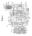
- Fig. 1 depicts an electric compressor according to an embodiment of the present invention, in particular, shows a case where the present invention is applied to a hybrid compressor.
- Fig. 2 depicts a structure for enhancing the vibration proof performance of the terminal joint of an electric motor incorporated into the hybrid compressor depicted in Fig. 2
- this structure shown in Fig. 2 is a structure capable of being applied to not only the hybrid compressor but also an electric compressor merely having an incorporated electric motor as an only one drive source.
- Hybrid compressor 1 is formed as a scroll type compressor, and has a first compression mechanism 2 and a second compression mechanism 3.
- First compression mechanism 2 has a fixed scroll 10, a movable scroll 11 forming a plurality of pairs of operational spaces (fluid pockets) 12 by engaging with fixed scroll 10, a drive shaft 13 driving movable scroll 11 at an orbital movement by engaging with movable scroll 11, an electromagnetic clutch 15 for an on-off operation of the transmission of a driving force between a pulley 14, to which the driving force from a prime mover for running a vehicle (not shown) provided as a first drive source is transmitted, and the drive shaft 13, a ball coupling 16 provided as a rotation preventing means for preventing the rotation of movable scroll 11, and a suction port 18 formed on a casing 17.
- the fluid to be compressed for example, refrigerant gas
- a suction path 19 The fluid to be compressed (for example, refrigerant gas) sucked from suction port 18 into a suction chamber 20 through a suction path 19 is taken into operational spaces 12, the operational spaces 12 are moved toward the center of fixed scroll 10 while the volumes of the operational spaces 12 are decreased, and by this operation, the refrigerant gas in the operational spaces 12 is compressed.
- a discharge hole 21 is formed on the central portion of fixed scroll 10, and the compressed refrigerant gas is discharged to a high-pressure side of an external refrigerant circuit through the discharge hole 21, a discharge path 22 and a discharge port 23.
- second compression mechanism 3 has a fixed scroll 30, a movable scroll 31 forming a plurality of pairs of operational spaces (fluid pockets) 32 by engaging with fixed scroll 30, a drive shaft 33 driving movable scroll 31 at an orbital movement by engaging with movable scroll 31, and a ball coupling 34 provided as a rotation preventing means for preventing the rotation of movable scroll 31.
- An electric motor 35 is incorporated in order to drive the drive shaft 33 of this second compression mechanism 3.
- Electric motor 35 has a rotor 36 fixed to drive shaft 33 and a stator 37, the stator 37 is fixed to a stator housing 38 or a stator housing 38 which is formed as a part of the compressor housing, and the whole of electric motor 35 is contained in the stator housing 38.
- the fluid to be compressed for example, refrigerant gas
- the fluid to be compressed for example, refrigerant gas
- suction port 18 into suction chamber 20 of first compression mechanism 2 is sucked into a suction chamber 40 of second compression mechanism 3 through a communication path 39
- the gas is taken into operational spaces 32
- the operational spaces 32 are moved toward the center of fixed scroll 30 while the volumes of the operational spaces 32 are decreased, and by this operation, the refrigerant gas in the operational spaces 32 is compressed.
- a discharge hole 41 is formed on the central portion of fixed scroll 30, and the compressed refrigerant gas is discharged to the high-pressure side of the external refrigerant circuit through the discharge hole 41 and a discharge path 42.
- fixed scroll 10 of first compression mechanism 2 and fixed scroll 30 of second compression mechanism 3 are disposed back to back, and both fixed scrolls 10 and 30 are formed as an integrated fixed scroll member 43.
- first compression mechanism 2 of hybrid compressor 1 When only first compression mechanism 2 of hybrid compressor 1 is operated, an electricity is not supplied to electric motor 35 for driving second compression mechanism 3, and the electric motor 35 is not rotated. Therefore, second compression mechanism 3 does not operate.
- the hybrid compressor 1 is driven only by electric motor 35, the electric motor 35 is turned to be on and rotated, the rotation of the electric motor 35 is transmitted to drive shaft 33 of second compression mechanism 3, and the orbital movement of movable scroll 31 is performed by the drive shaft 33.
- electromagnetic clutch 15 of first compression mechanism 2 is not excited, and the rotation of the prime mover for running a vehicle as a first drive source is not transmitted to the first compression mechanism 2. Therefore, first compression mechanism 2 does not operate.
- first and second compression mechanisms 2 and 3 When both first and second compression mechanisms 2 and 3 are driven simultaneously, the driving force from the prime mover for running a vehicle is transmitted to movable scroll 11 of first compression mechanism 2 as well as electric motor 35 is turned to be on and the driving force thereof is transmitted to movable scroll 31 of second compression mechanism 3.
- terminal portion 50 of electric motor 35 is disposed at an upper portion of the hybrid compressor 1 which is in a mounted condition.
- joints 53 between external terminals 51 for supplying power to electric motor 35 and the ends of wires 52 from stator 37 of electric motor 35 are provided.
- Joints 53 are disposed in a hollow projected portion 54 which is formed on stator housing 38 and extends toward outside, and external terminals 51 for supplying power are attached to a lid 55 which substantially can close this hollow projected portion 54.
- the above-described joint 53 is formed via a coupler structure which comprises a tab housing 56 holding external terminal 51 for supplying power and a receptacle housing 57 holding the end of wire 52 from stator 37 and being fitted to the tab housing 56 with each other.
- a hollow portion 58 for containing receptacle housing 57 is formed and a supporting portion 59 extending downward is provided at the central portion of tab housing 56.
- an O-ring 61 is interposed between the outer circumferential surface of supporting portion 59 of tab housing 56 and the inner circumferential surface of hollow portion 60 of receptacle housing 57. This O-ring 61 mainly functions to prevent vibration in the horizontal direction between tab housing 56 and receptacle housing 57.
- an elastic material 62 is interposed between the outer end portion (tip portion) of supporting portion 59 of tab housing 56 (or the inner end portion in accordance with the fitting structure with receptacle housing 57) and the inner end portion (bottom portion) of hollow portion 60 of receptacle housing 57 (or the outer end portion in accordance with the fitting structure with tab housing 56).
- This elastic material 62 is formed from a vibration proof rubber in this embodiment, and it is formed as a member which can be deformed in its longitudinal direction by compression and can be expanded in its radial direction.
- a lock mechanism 63 is disposed between hollow portion 58 of tab housing 56 and the outer circumferential portion of receptacle housing 57 for engaging both housings to each other.
- a claw 64 provided on the side of tab housing 56 and a claw 65 provided on the side of receptacle housing 57 engage each other. Bu such a structure, getting out of receptacle housing 57 from tab housing 56 may be prevented, and by a condition where tab housing 56 is pressed from upper side relatively to receptacle housing 57 at the time of the engaging, the above-described elastic material 62 can be compressed and fixed to make the elastic material 62 exhibit the above-described vibration preventing function.
- a wave washer 66 as an elastic member capable of pressing tab housing 56 toward the inside of the compressor housing, particularly in this embodiment, toward the inside of hollow projected portion 54 of stator housing 38.
- This elastic member may be a member capable of exhibiting a pressing force except wave washer 66, for example, another spring member.
- Tab housing 56 abuts a projection 67 formed in hollow projected portion 54, and it is held by the pressing force of wave washer 66 relative to lid 55.
- the function of tab housing 56 for preventing vibration in the vertical direction can be exhibited.
- a flat washer 68 is interposed in order to prevent the surface of tab housing 56 from being deformed by the pressing force of wave washer 66.
- an O-ring 69 is preferably interposed between the outer circumferential surface, and the compressor housing, in this embodiment, the inner circumferential surface of hollow projected portion 54 of stator housing 38 .
- a pressing plate 70 is attached to the lower portion of receptacle housing 57 as a holding member for holding wire 52 from stator 37, and a wire holding means 71 is provided on this pressing plate 70 for elastically holding wire 52.
- This wire holding means 71 may be formed from a rubber member for example. Wire 52 is elastically held by wire holding means 71, thereby enhancing the vibration proof performance of this portion.
- This wire holding means portion may be formed, for example, as shown in Fig. 3 .
- wire holding means 80 which elastically holds wire 81 from stator 37 and formed from a rubber member, is attached to wire 81 or/and terminal 82 by direct caulking and the like, and at that state, it is fitted and held in receptacle housing 83.
- the aforementioned pressing plate 70 may be omitted, and the assembling performance may be improved and the cost may be reduced.
- a gap between wire 81 from stator 37 and receptacle housing 83 can be abolished and pressing plate 70 can be abolished, the insulation property at this portion may be improved.
- the vibration proof performance of the terminal joint can be enhanced, and occurrence of the disconnection and instantaneous interruption of the terminal joint can be prevented or suppressed. Further, as compared with the aforementioned case of injecting an epoxy resin, because the time for the preparation and curing of the resin is omitted, a good productivity may be ensured.
- the present invention can be applied to any electric compressor incorporating an electric motor for driving a compression mechanism, in particular, can be applied also to an electric compressor of a hybrid compressor in which the respective compression mechanisms are driven by an incorporated electric motor and another drive source different therefrom.
Landscapes
- Engineering & Computer Science (AREA)
- Power Engineering (AREA)
- Mechanical Engineering (AREA)
- General Engineering & Computer Science (AREA)
- Compressor (AREA)
- Applications Or Details Of Rotary Compressors (AREA)
- Rotary Pumps (AREA)
Applications Claiming Priority (2)
| Application Number | Priority Date | Filing Date | Title |
|---|---|---|---|
| JP2005156757A JP5053523B2 (ja) | 2004-12-24 | 2005-05-30 | 電動圧縮機 |
| PCT/JP2006/309150 WO2006129448A1 (fr) | 2005-05-30 | 2006-05-02 | Compresseur electrique |
Publications (2)
| Publication Number | Publication Date |
|---|---|
| EP1887225A1 true EP1887225A1 (fr) | 2008-02-13 |
| EP1887225A4 EP1887225A4 (fr) | 2012-11-28 |
Family
ID=37481380
Family Applications (1)
| Application Number | Title | Priority Date | Filing Date |
|---|---|---|---|
| EP06746000A Withdrawn EP1887225A4 (fr) | 2005-05-30 | 2006-05-02 | Compresseur electrique |
Country Status (5)
| Country | Link |
|---|---|
| US (1) | US8235687B2 (fr) |
| EP (1) | EP1887225A4 (fr) |
| CN (1) | CN101184919B (fr) |
| CA (1) | CA2610060C (fr) |
| WO (1) | WO2006129448A1 (fr) |
Cited By (1)
| Publication number | Priority date | Publication date | Assignee | Title |
|---|---|---|---|---|
| WO2017162379A1 (fr) * | 2016-03-24 | 2017-09-28 | Robert Bosch Gmbh | Machine électrique comprenant une rondelle-ressort et procédé de fabrication d'une machine électrique |
Families Citing this family (12)
| Publication number | Priority date | Publication date | Assignee | Title |
|---|---|---|---|---|
| US8939734B2 (en) * | 2007-08-28 | 2015-01-27 | Emerson Climate Technologies, Inc. | Molded plug for a compressor |
| JP5308650B2 (ja) * | 2007-10-23 | 2013-10-09 | サンデン株式会社 | 電動圧縮機の端子装置 |
| WO2010080984A2 (fr) | 2009-01-09 | 2010-07-15 | Emerson Climate Technologies, Inc. | Compresseur ayant un ensemble borne à fiche |
| US8939735B2 (en) | 2009-03-27 | 2015-01-27 | Emerson Climate Technologies, Inc. | Compressor plug assembly |
| FR2975447B1 (fr) * | 2011-05-19 | 2013-05-31 | Valeo Thermal Sys Japan Co | Compresseur electrique modulaire avec dispositif d'assemblage |
| US9480177B2 (en) | 2012-07-27 | 2016-10-25 | Emerson Climate Technologies, Inc. | Compressor protection module |
| JP5518169B1 (ja) * | 2012-12-12 | 2014-06-11 | 三菱重工業株式会社 | 電動圧縮機およびその組立方法 |
| CN104295496B (zh) * | 2014-10-22 | 2018-09-11 | 广东美芝制冷设备有限公司 | 外转子式压缩机 |
| DE102015114192A1 (de) * | 2015-08-26 | 2017-03-02 | Ebm-Papst Mulfingen Gmbh & Co. Kg | Verbindungssystem zur Steckerpositionierung |
| DE102016202226A1 (de) * | 2016-02-15 | 2017-08-17 | Bühler Motor GmbH | Bürstenloser Gleichstrommotor zum Antrieb einer Pumpe |
| CN112943576B (zh) * | 2021-04-15 | 2024-05-17 | 苏州大学张家港工业技术研究院 | 一种消除飞线疲劳的动圈式直线对置振荡压缩机 |
| CN116093640B (zh) * | 2022-06-21 | 2025-11-28 | 中国电力科学研究院有限公司 | 一种快速接线装置及具有该快速接线装置的互感器 |
Family Cites Families (17)
| Publication number | Priority date | Publication date | Assignee | Title |
|---|---|---|---|---|
| US3457867A (en) * | 1968-01-25 | 1969-07-29 | Red Jacket Mfg Co | Fluid pumping system |
| JPS5937862U (ja) | 1982-08-31 | 1984-03-09 | 株式会社東芝 | 圧縮機の端子保護箱 |
| JPS59110896A (ja) * | 1982-12-15 | 1984-06-26 | Ebara Corp | 水中モ−タポンプ |
| US4836794A (en) * | 1988-08-05 | 1989-06-06 | Kern Engineering & Mfg. Corp. | EMI and environmentally protected connector cap |
| JPH0417787A (ja) | 1990-05-07 | 1992-01-22 | Sanyo Electric Co Ltd | 密閉型圧縮機 |
| JP3047159B2 (ja) * | 1995-11-09 | 2000-05-29 | 矢崎総業株式会社 | コネクタ嵌合構造 |
| JP3259817B2 (ja) * | 1996-02-09 | 2002-02-25 | 矢崎総業株式会社 | カバー付き防水コネクタ |
| JP3742887B2 (ja) * | 1997-06-18 | 2006-02-08 | ダイキン工業株式会社 | スクロール圧縮機 |
| JP2001085111A (ja) * | 1999-09-10 | 2001-03-30 | Sumitomo Wiring Syst Ltd | コネクタ |
| JP2002155862A (ja) * | 2000-11-22 | 2002-05-31 | Toyota Industries Corp | 圧縮機 |
| JP2002276550A (ja) | 2001-03-14 | 2002-09-25 | Matsushita Electric Ind Co Ltd | 電動機内蔵の圧縮機と外部配線との接続方法、それに用いる接続具、それらを用いた電動機内蔵の圧縮機 |
| JP4044341B2 (ja) * | 2001-09-14 | 2008-02-06 | サンデン株式会社 | ハイブリッド圧縮機 |
| AU2003200332B2 (en) * | 2002-02-08 | 2005-11-17 | Sanden Corporation | Hybrid compressor |
| JP3654272B2 (ja) * | 2002-08-26 | 2005-06-02 | アイシン・エィ・ダブリュ株式会社 | 車両用モータの配線接続装置 |
| JP2004270614A (ja) * | 2003-03-11 | 2004-09-30 | Sanden Corp | 電動圧縮機 |
| US7197892B2 (en) * | 2003-06-11 | 2007-04-03 | Denso Corporation | Encapsulated electrically driven compressor |
| JP4090409B2 (ja) * | 2003-09-10 | 2008-05-28 | 日本圧着端子製造株式会社 | コネクタのハウジング構造 |
-
2006
- 2006-05-02 CA CA2610060A patent/CA2610060C/fr not_active Expired - Fee Related
- 2006-05-02 US US11/915,931 patent/US8235687B2/en not_active Expired - Fee Related
- 2006-05-02 CN CN2006800190438A patent/CN101184919B/zh not_active Expired - Fee Related
- 2006-05-02 EP EP06746000A patent/EP1887225A4/fr not_active Withdrawn
- 2006-05-02 WO PCT/JP2006/309150 patent/WO2006129448A1/fr not_active Ceased
Cited By (1)
| Publication number | Priority date | Publication date | Assignee | Title |
|---|---|---|---|---|
| WO2017162379A1 (fr) * | 2016-03-24 | 2017-09-28 | Robert Bosch Gmbh | Machine électrique comprenant une rondelle-ressort et procédé de fabrication d'une machine électrique |
Also Published As
| Publication number | Publication date |
|---|---|
| WO2006129448A1 (fr) | 2006-12-07 |
| CA2610060C (fr) | 2012-03-13 |
| CN101184919B (zh) | 2010-04-21 |
| CN101184919A (zh) | 2008-05-21 |
| EP1887225A4 (fr) | 2012-11-28 |
| CA2610060A1 (fr) | 2006-12-07 |
| US8235687B2 (en) | 2012-08-07 |
| US20090129954A1 (en) | 2009-05-21 |
Similar Documents
| Publication | Publication Date | Title |
|---|---|---|
| JP6507270B2 (ja) | 圧縮機 | |
| KR102583934B1 (ko) | 압축기 | |
| CA2610060C (fr) | Compresseur electrique | |
| JP2014114795A (ja) | 電動圧縮機およびその組立方法 | |
| US20090315418A1 (en) | Electric wire holding structure for electric compressor and electric wire holding method for electric compressor | |
| US7806712B2 (en) | Electric compressor | |
| US8231365B2 (en) | Electric compressor | |
| JP3994731B2 (ja) | 電動式圧縮機 | |
| US7344400B2 (en) | Terminal connection structure of motor incorporated within a compressor | |
| EP1867874B1 (fr) | Compresseur entraine par un moteur electrique | |
| US20100247348A1 (en) | Terminal device for electric compressor | |
| EP2221477A1 (fr) | Dispositif de borne d'électro-compresseur | |
| EP2230405A1 (fr) | Dispositif de borne pour compresseur électrique | |
| JP5053523B2 (ja) | 電動圧縮機 | |
| KR102500648B1 (ko) | 압축기 | |
| JP2007315222A (ja) | 電動圧縮機 | |
| JP2012021473A (ja) | 電動圧縮機 | |
| JP4062060B2 (ja) | 密閉型圧縮機 | |
| KR20240097550A (ko) | 전동 압축기 |
Legal Events
| Date | Code | Title | Description |
|---|---|---|---|
| PUAI | Public reference made under article 153(3) epc to a published international application that has entered the european phase |
Free format text: ORIGINAL CODE: 0009012 |
|
| 17P | Request for examination filed |
Effective date: 20071128 |
|
| AK | Designated contracting states |
Kind code of ref document: A1 Designated state(s): DE FR |
|
| DAX | Request for extension of the european patent (deleted) | ||
| RBV | Designated contracting states (corrected) |
Designated state(s): DE FR |
|
| A4 | Supplementary search report drawn up and despatched |
Effective date: 20121030 |
|
| RIC1 | Information provided on ipc code assigned before grant |
Ipc: F04C 23/02 20060101ALI20121024BHEP Ipc: H02K 5/22 20060101ALI20121024BHEP Ipc: F04C 18/02 20060101ALI20121024BHEP Ipc: F04C 23/00 20060101ALI20121024BHEP Ipc: F04B 39/00 20060101AFI20121024BHEP Ipc: F04C 29/00 20060101ALI20121024BHEP Ipc: H01R 13/639 20060101ALI20121024BHEP |
|
| GRAP | Despatch of communication of intention to grant a patent |
Free format text: ORIGINAL CODE: EPIDOSNIGR1 |
|
| INTG | Intention to grant announced |
Effective date: 20130829 |
|
| STAA | Information on the status of an ep patent application or granted ep patent |
Free format text: STATUS: THE APPLICATION IS DEEMED TO BE WITHDRAWN |
|
| 18D | Application deemed to be withdrawn |
Effective date: 20140109 |