EP1890118A2 - Ausgabesystem für visköses Material und Verfahren mit Feedback-Regelung - Google Patents
Ausgabesystem für visköses Material und Verfahren mit Feedback-Regelung Download PDFInfo
- Publication number
- EP1890118A2 EP1890118A2 EP07020879A EP07020879A EP1890118A2 EP 1890118 A2 EP1890118 A2 EP 1890118A2 EP 07020879 A EP07020879 A EP 07020879A EP 07020879 A EP07020879 A EP 07020879A EP 1890118 A2 EP1890118 A2 EP 1890118A2
- Authority
- EP
- European Patent Office
- Prior art keywords
- amount
- viscous material
- dispenser
- valve
- control
- Prior art date
- Legal status (The legal status is an assumption and is not a legal conclusion. Google has not performed a legal analysis and makes no representation as to the accuracy of the status listed.)
- Withdrawn
Links
Images
Classifications
-
- G—PHYSICS
- G01—MEASURING; TESTING
- G01F—MEASURING VOLUME, VOLUME FLOW, MASS FLOW OR LIQUID LEVEL; METERING BY VOLUME
- G01F25/00—Testing or calibration of apparatus for measuring volume, volume flow or liquid level or for metering by volume
- G01F25/0092—Testing or calibration of apparatus for measuring volume, volume flow or liquid level or for metering by volume for metering by volume
Definitions
- the present invention generally relates to automated equipment used for dispensing viscous materials. More particularly, the invention relates to systems and methods for dispensing accurate amounts of viscous material, such as during printed circuit (PC) board assembly.
- PC printed circuit
- viscous materials In certain fields, such as the field of PC board assembly, small amounts of viscous materials must be applied accurately to a substrate.
- viscous materials have a viscosity greater than about 50 centipoise and include, for example, adhesives, solder flux, solder paste, solder mask, grease, oil, encapsulants, potting compounds, epoxies, dye attach pastes, silicones and RTV.
- Dispensing systems may include either a syringe dispenser or an ON/OFF dispenser valve.
- Syringe dispensers are used as contact dispensers actuated with pneumatic mechanisms, electromechanical mechanisms or positive displacement valves.
- the tip of a syringe dispenser is placed very close to the substrate, for example, at a distance of 0.005 inches for a very small droplet and a distance of about 0.060 inches for a larger droplet.
- the viscous material is pushed out of the syringe tip and contacts the substrate while it is still connected to the syringe tip.
- Syringe style contact dispensers have certain desirable attributes.
- one of the main drawbacks with syringe dispensers relates to their relatively slow operating speed. That is, it is difficult to dispense more than about ten dots of viscous material per second with a syringe dispenser. Stringing of viscous material away from the syringe tip is also a problem that reduces accuracy and quality.
- Dispenser valves which can operate as non-contact ON/OFF dispensers, exhibit certain advantages relative to other dispensing systems and methods. For example, dispenser valves can more quickly dispense a number of minute drops of viscous material on a PC board. This is generally due to elimination of z-axis movement which is necessary with contact dispensers. Also, dispenser valves can reduce or eliminate stringing problems and other problems associated with contact dispensing methods since the dispenser nozzle may be maintained at a greater distance from the substrate. Dispenser valves also allow a greater amount of viscous material to be cleanly and accurately dispensed at a single location by discharging more than one drop at the location.
- a system which accurately dispenses controlled amounts of viscous material by feeding information on the dispensed amount of viscous material back to one of various control devices which operate a viscous material dispenser.
- the system can more specifically comprise a pressurized supply of viscous material, a dispenser connected in fluid communication with the pressurized supply and a feedback control operatively connected with the pressurized supply.
- the feedback control includes a viscous material measuring device operative to measure a dispensed amount of the viscous material.
- a memory device stores a value representing a control amount of the viscous material.
- a comparing device compares the dispensed amount with the control amount and produces a correcting output signal which may then be used directly or indirectly to adjust the dispensed amount. While the preferred embodiment of this invention involves the use of at least one non-contact dispenser, various aspects of the invention will also benefit contact dispensing systems.
- the output signal may be used by a first transducer to change the pressure of the pressurized supply of viscous material.
- the output signal may be used by a second transducer to adjust fluid pressure supplied for operating the dispenser.
- the output signal may be used to change the duration that the dispenser is maintained in an open position to dispense the viscous material.
- the feedback control first changes the pressure of the pressurized supply of viscous material within predefined limits. If this change reaches one of the predefined limits and the dispensed amount of material does not adequately match the control amount, then the second manner of adjustment is used to correct the dispensed amount. If this still does not produce the desired amount of dispensed material, then the system reverts to the third manner of adjusting the dispensed amount as described above.
- the pressurized supply connected with the dispenser more specifically includes a syringe containing the viscous material and operated by a pressurized fluid which forces viscous material from the syringe into the dispenser.
- the first transducer may be a voltage to pressure transducer which converts a voltage signal representing the desired correction into a pressure of the pressurized fluid used to operate the syringe.
- the dispenser may be a known ON/OFF non-contact dispenser valve used for dispensing small amounts of viscous material as drops.
- the dispenser valve may be operated by a conventional solenoid-operated valve which supplies a fluid pressure, such as air pressure, to the non-contact dispenser valve.
- the feedback control system may be used to adjust the fluid pressure and/or the ON time of the control valve such that the non-contact dispenser valve dispenses an amount of viscous material which is closer to the control amount than the dispensed amount.
- the viscous material measuring device may include, for example, a weigh scale or any other suitable measuring device, such as a vision system which measures dot diameter, area or volume.
- a method according to the invention may include discharging a first amount of the viscous material from the dispenser, measuring the first amount of viscous material, comparing the first amount to a commanded or desired control amount stored in a memory device, and adjusting the pressure of the pressurized supply to correct for a difference between the first amount and the control amount.
- Another method which may be used alternatively or in conjunction with the previously described method involves discharging a first amount of the viscous material from a dispenser valve, measuring the first amount of viscous material, comparing the first amount to a commanded control amount stored in a memory device, and adjusting a fluid operating pressure used to actuate the dispenser valve to correct for a difference between the first amount and the commanded control amount.
- An alternative or additional method which may be practiced in accordance with the invention includes discharging a first amount of the viscous material from an ON/OFF, non-contact dispenser valve, measuring the first amount of viscous material, comparing the first amount to a commanded control amount stored in a memory device, and adjusting the ON time to correct for a difference between the first amount and the control amount.
- the present invention provides various improvements in the area of dispensing accurate, discrete amounts of viscous material, especially in the field of PC board manufacture.
- the invention may also apply easily and beneficially to other areas of dispensing technology. Additional features, advantages and configurations of the invention will become more readily apparent to those of ordinary skill in the art upon review of the following detailed description of the preferred embodiment and the appended claims.
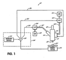
- a dispensing system 10 configured in accordance with the invention generally includes an ON/OFF dispenser valve 12 which, in this illustrative embodiment, is a non-contact dispenser valve specifically designed for dispensing minute amounts of viscous material.
- a preferred dispenser valve 12 is more specifically shown and described in U.S. Patent No. 5,747,102 , assigned to the assignee of this invention, and the disclosure of which is hereby incorporated by reference herein. Other contact or non-contact dispensers may also benefit from one or more of the aspects of this invention.
- Non-contact dispenser 12 further includes a syringe-style supply device 14 for supplying pressurized viscous material to dispenser 12.
- a control valve 16 which preferably takes the form of a solenoid-operated air valve, may be directly connected to dispenser 12.
- control valve 16 supplies pressurized air into dispenser 12 to force an internal valve stem (not shown) into an open position.
- a conventional spring return mechanism 18 may be provided for moving the valve stem into a closed position when the pressurized air from control valve 16 is sufficiently reduced or turned off. Further structural details and operation of dispenser 12 may be understood by referring to the above-incorporated patent.
- Non-contact dispenser 12 operates to dispense a specific amount of viscous material 20 from a nozzle 22 as schematically shown in exaggerated form in Fig. 1.
- a sample 20 or specific amount of viscous material may be formed by one or more dispensed drops.
- a measuring device 24, in the preferred form of a weigh scale is used in a feedback control system to accurately control the amount of dispensed viscous material.
- Other types of feedback devices may be substituted for weigh scale 24 and, for example, may include other drop size measurement devices such as vision systems, including cameras, L.E.D.'s or phototransistors for measuring the diameter, area and/or volume of the dispensed material.
- Weigh scale 24 is operatively connected to a controller 26 which includes a comparing device 28.
- Comparing device 28 may be a comparison circuit which compares a signal representing a measured amount of viscous material, i.e., sample 20, with a signal representing a control amount stored within controller 26.
- the control amount represents the desired amount for a particular application.
- the controller may be a programmable logic controller (PLC) or other microprocessor based controller, such as a computer, or other conventional control devices capable of carrying out the functions described herein as will be understood by those of ordinary skill.
- PLC programmable logic controller
- one or more correction values or correcting signals 30, 32, 34 are output to adjust the amount of dispensed material.
- output signal 30 may be directed to a voltage-to-pressure transducer 36 which converts the voltage to an air pressure such that a corrected air pressure is sent from an air supply 38 to an air line 40 connected with syringe 14.
- output signal 32 may be sent to a second voltage-to-pressure transducer 42 which controls air pressure to solenoid-operated air valve 16.
- voltage-to-pressure transducer 42 converts the output signal 32 into an air pressure such that a corrected air pressure is sent from an air supply 44 into an air line 46 connected with solenoid-operated air valve 16 and, ultimately, with dispenser valve 12.
- the third manner of adjusting the amount of dispensed viscous material involves adjusting the ON time of solenoid-operated air valve 16. As the ON time increases, the amount of dispensed material also increases and vice versa. The ON time is controlled by changing the duration of output signal 34 sent to activate or open solenoid-operated air valve 16.
- the duration of output signal 34 may be determined by controller 26 after comparing the dispensed amount of material measured by weigh scale 24 with a desired amount or control amount stored in controller 26.
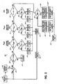
- Flow chart 50 represents the process steps carried out by controller 26 used to dispense a controlled amount of viscous material, such as a sample drop 20.
- the process steps may be carried out with conventional processing hardware, as mentioned above, and as will be readily appreciated by those of ordinary skill.
- the calibration process is initiated at step 52 and, in conjunction with this test initiation, a sample 20 of viscous material, such as in the form of one or more drops, is dispensed from dispenser valve 12.
- the amount or size of sample 20 is measured at step 56 by being weighed on weigh scale 24.
- a weight value W fb is sent to comparing device 28 of controller 26 and comparing device 28 subtracts this value from a commanded weight value W c retrieved from a memory device 58 of controller 26.
- the resulting value represents an error value ERR.
- this error value ERR is checked for acceptability. That is, if the error is less than or equal to 5% of the desired weight W c , then no changes are necessary in calibration.
- This condition as represented at step 64, may be indicated to an operator by signaling the operator with a light or other indicator. Of course, different applications may have different acceptable error values.
- the controller 26 determines whether the pressure within syringe 14 falls within the operating range of 10 psi to 30 psi. That is, if the pressure within syringe 14 is within an appropriate operating range, then corrective action by varying the pressure supplied to syringe 14 is possible. If this is the case, at step 68, the controller determines whether the error ERR is greater than zero or positive, meaning that the desired size or weight of sample 20 is greater than the feedback weight or weight of the sample 20. In this case, the pressure fed to syringe 14 may be incrementally increased, for example, by 2 psi.
- the weight of sample 20 or W fb is greater than the desired size or weight and the pressure to syringe 14 is decreased by 2 psi at step 72.
- the pressure may be changed in a more proportional and accurate manner relative to the error.
- a sample is again dispensed onto weigh scale 24 and the process is repeated with measurement at step 56 and a comparison being made by comparing device 28 to determine the error ERR. If the error is less than or equal to 5% of the desired size or weight W c' then no changes or corrections are necessary as indicated at step 64. If additional correction is necessary, the process is repeated as described above with respect to step 66 until the pressure within syringe 14 falls outside of the 10-30 psi operating range. At this point, if correction is still necessary, the process continues to step 74.
- controller 26 determines whether the pressure of solenoid valve 16 is within a proper operating range. In this embodiment, this range is between 60 psi and 90 psi. If the operating pressure is within this range, then at step 76 controller 26 determines whether the error ERR is positive or negative. If positive, meaning that the weight of sample 20 is less than the desired weight W c , the pressure to solenoid valve 16 is increased by 2 psi. If the error is negative, meaning that the weight of sample 20 is greater than the desired weight W c , then the pressure to solenoid valve 16 is decreased by 2 psi. Again, the amount of these corrective pressure changes may instead be determined and made in proportion to the amount of the error ERR.
- step 78 or 80 After either step 78 or 80 is performed, another sample is dispensed at step 54 and the process is repeated to determine whether the error is within an acceptable amount. If the error is still unacceptable, then the process is repeated until the pressure within solenoid 16 is outside of the 60-90 psi operating range, then the process will continue to step 82 and use solenoid ON time as an additional method of correction.
- Solenoid ON time will also have an operating range, for example, which may be between 7 milliseconds and 15 milliseconds as indicated at step 82. As long as the ON time stored within controller 26 is within this range, adjustments may be made to the duration that solenoid-operated air valve 16 is maintained ON to change the amount of dispensed material. Thus, at step 84, if the error is positive, the ON time will be increased by 2 milliseconds at step 86 and, if the error is negative, the ON time will be decreased by 2 milliseconds as indicated at step 88. Like the incremental pressure changes described above, these changes in ON time may instead be determined and made in proportion to the detected error.
- step 86 or step 88 a sample will again be dispensed and measured and the process will be repeated to determine whether the dispensed sample is within an acceptable weight range. If it is not, the correction process continues until the ON time adjustments can no longer be made, i.e., until the ON time falls outside of the 7-15 millisecond range.
- controller 26 determines whether the error that remains is positive or negative. If the error is positive, the system will indicate that the maximum size has been reached with the particular hardware configuration. As indicated at step 96, the hardware may be appropriately changed, such as by increasing the nozzle size, or dispenser valve 12 may increase the number of drops used to form sample 20.
- controller 26 indicates that the minimum size has been reached with the hardware configuration. As indicated at step 100, the nozzle size may be decreased or a decrease in the number of drops may be used to appropriately decrease the size of sample 20. Once these changes have been made, the test may be restarted as indicated at step 102.
- the correcting output signals may not be signals directly to the transducers or to the control valve, but may be conditioned in some manner recognizable by the transducer or control valve to make the appropriate correction.
- the transducer devices and other control devices are not necessarily single devices or units but may be multiple sensing and control components which, together, are capable of carrying out the functions expressed herein. This has been a description of the present invention, along with the preferred methods of practicing the present invention as currently known. However, the invention itself should only be defined by the appended claims, wherein we claim:
Landscapes
- Physics & Mathematics (AREA)
- Fluid Mechanics (AREA)
- General Physics & Mathematics (AREA)
- Coating Apparatus (AREA)
- Application Of Or Painting With Fluid Materials (AREA)
- Flow Control (AREA)
Applications Claiming Priority (2)
| Application Number | Priority Date | Filing Date | Title |
|---|---|---|---|
| US09/298,325 US6173864B1 (en) | 1999-04-23 | 1999-04-23 | Viscous material dispensing system and method with feedback control |
| EP00925953A EP1173735B1 (de) | 1999-04-23 | 2000-04-13 | Abgabevorrichtung und abgabeverfahren für viskoses material mit rückkoppelungsregelkreis |
Related Parent Applications (1)
| Application Number | Title | Priority Date | Filing Date |
|---|---|---|---|
| EP00925953A Division EP1173735B1 (de) | 1999-04-23 | 2000-04-13 | Abgabevorrichtung und abgabeverfahren für viskoses material mit rückkoppelungsregelkreis |
Publications (2)
| Publication Number | Publication Date |
|---|---|
| EP1890118A2 true EP1890118A2 (de) | 2008-02-20 |
| EP1890118A3 EP1890118A3 (de) | 2008-02-27 |
Family
ID=23150025
Family Applications (3)
| Application Number | Title | Priority Date | Filing Date |
|---|---|---|---|
| EP06024769A Withdrawn EP1754962A3 (de) | 1999-04-23 | 2000-04-13 | Abgabevorrichtung und Abgabeverfahren für viskoses Material mit Rückkoppelungsregelkreis |
| EP00925953A Expired - Lifetime EP1173735B1 (de) | 1999-04-23 | 2000-04-13 | Abgabevorrichtung und abgabeverfahren für viskoses material mit rückkoppelungsregelkreis |
| EP07020879A Withdrawn EP1890118A3 (de) | 1999-04-23 | 2000-04-13 | Ausgabesystem für visköses Material und Verfahren mit Feedback-Regelung |
Family Applications Before (2)
| Application Number | Title | Priority Date | Filing Date |
|---|---|---|---|
| EP06024769A Withdrawn EP1754962A3 (de) | 1999-04-23 | 2000-04-13 | Abgabevorrichtung und Abgabeverfahren für viskoses Material mit Rückkoppelungsregelkreis |
| EP00925953A Expired - Lifetime EP1173735B1 (de) | 1999-04-23 | 2000-04-13 | Abgabevorrichtung und abgabeverfahren für viskoses material mit rückkoppelungsregelkreis |
Country Status (6)
| Country | Link |
|---|---|
| US (1) | US6173864B1 (de) |
| EP (3) | EP1754962A3 (de) |
| JP (1) | JP4643021B2 (de) |
| AU (1) | AU4456700A (de) |
| DE (1) | DE60038228T2 (de) |
| WO (1) | WO2000065316A1 (de) |
Cited By (1)
| Publication number | Priority date | Publication date | Assignee | Title |
|---|---|---|---|---|
| EP4076899B1 (de) | 2020-07-01 | 2023-05-24 | Actega Artística, S.A.U. | Steuerungsverfahren und hochgeschwindigkeitseinspritzsystem |
Families Citing this family (53)
| Publication number | Priority date | Publication date | Assignee | Title |
|---|---|---|---|---|
| AU7262496A (en) | 1995-10-13 | 1997-04-30 | Nordson Corporation | Flip chip underfill system and method |
| US20030010792A1 (en) | 1998-12-30 | 2003-01-16 | Randy Forshey | Chemical mix and delivery systems and methods thereof |
| US6617079B1 (en) * | 2000-06-19 | 2003-09-09 | Mykrolis Corporation | Process and system for determining acceptibility of a fluid dispense |
| US6811301B2 (en) | 2002-03-29 | 2004-11-02 | Hydreclaim, Inc. | Feeder control system for an automated blender system |
| US6991825B2 (en) * | 2002-05-10 | 2006-01-31 | Asm Assembly Automation Ltd. | Dispensation of controlled quantities of material onto a substrate |
| JP4200758B2 (ja) * | 2002-12-26 | 2008-12-24 | 株式会社日立ハイテクノロジーズ | パネルの樹脂塗布方法、ディスプレイ用パネルの製造方法及び樹脂塗布装置 |
| US20050001869A1 (en) | 2003-05-23 | 2005-01-06 | Nordson Corporation | Viscous material noncontact jetting system |
| US20050048195A1 (en) * | 2003-08-26 | 2005-03-03 | Akihiro Yanagita | Dispensing system and method of controlling the same |
| US20050095367A1 (en) * | 2003-10-31 | 2005-05-05 | Babiarz Alec J. | Method of noncontact dispensing of viscous material |
| US20060029724A1 (en) * | 2004-08-06 | 2006-02-09 | Nordson Corporation | System for jetting phosphor for optical displays |
| US7749553B2 (en) * | 2005-01-31 | 2010-07-06 | Boston Scientific Scimed, Inc. | Method and system for coating a medical device using optical drop volume verification |
| US20070000603A1 (en) * | 2005-07-01 | 2007-01-04 | Nordson Corporation | Method of forming at least one continuous line of viscous material between two components of an electronic assembly |
| US20070069041A1 (en) * | 2005-09-27 | 2007-03-29 | Nordson Corporation | Viscous material dispensing systems with parameter monitoring and methods of operating such systems |
| US20070145164A1 (en) * | 2005-12-22 | 2007-06-28 | Nordson Corporation | Jetting dispenser with multiple jetting nozzle outlets |
| US7913879B2 (en) | 2006-03-06 | 2011-03-29 | The Coca-Cola Company | Beverage dispensing system |
| US7757896B2 (en) | 2006-03-06 | 2010-07-20 | The Coca-Cola Company | Beverage dispensing system |
| US9415992B2 (en) | 2006-03-06 | 2016-08-16 | The Coca-Cola Company | Dispenser for beverages having a rotary micro-ingredient combination chamber |
| US10631558B2 (en) | 2006-03-06 | 2020-04-28 | The Coca-Cola Company | Methods and apparatuses for making compositions comprising an acid and an acid degradable component and/or compositions comprising a plurality of selectable components |
| US9821992B2 (en) | 2006-03-06 | 2017-11-21 | The Coca-Cola Company | Juice dispensing system |
| US10280060B2 (en) | 2006-03-06 | 2019-05-07 | The Coca-Cola Company | Dispenser for beverages having an ingredient mixing module |
| US8960500B2 (en) | 2006-03-06 | 2015-02-24 | The Coca-Cola Company | Dispenser for beverages including juices |
| JP4868515B2 (ja) * | 2006-11-01 | 2012-02-01 | 武蔵エンジニアリング株式会社 | 液体材料の充填方法、装置およびプログラム |
| US8162176B2 (en) | 2007-09-06 | 2012-04-24 | The Coca-Cola Company | Method and apparatuses for providing a selectable beverage |
| MX2010002291A (es) | 2007-09-06 | 2010-05-03 | Coca Cola Co | Sistemas y metodos de seleccion y despachado de productos. |
| US8765212B2 (en) | 2007-09-21 | 2014-07-01 | Nordson Corporation | Methods for continuously moving a fluid dispenser while dispensing amounts of a fluid material |
| WO2009040352A1 (fr) * | 2007-09-24 | 2009-04-02 | Berner Fachhochschule für Technik und Informatik HTI | Dispositif pour le dépôt de couches |
| WO2009070568A1 (en) * | 2007-11-29 | 2009-06-04 | Nordson Corporation | Method of dispensing a viscous material |
| KR101615509B1 (ko) * | 2008-09-18 | 2016-04-26 | 노드슨 코포레이션 | 자동화 진공 이용 밸브 프라이밍 시스템 및 사용 방법 |
| US20100108256A1 (en) * | 2008-11-05 | 2010-05-06 | Western Digital Technologies, Inc. | Closed loop control of adhesive dot characteristics |
| US8240508B2 (en) * | 2008-12-29 | 2012-08-14 | Gojo Industries, Inc. | Low cost radio frequency identification (RFID) dispensing systems |
| US8757511B2 (en) | 2010-01-11 | 2014-06-24 | AdvanJet | Viscous non-contact jetting method and apparatus |
| WO2011123503A1 (en) * | 2010-04-01 | 2011-10-06 | B & H Manufacturing Company, Inc. | Extrusion application system |
| US8753713B2 (en) | 2010-06-05 | 2014-06-17 | Nordson Corporation | Jetting dispenser and method of jetting highly cohesive adhesives |
| US9346075B2 (en) | 2011-08-26 | 2016-05-24 | Nordson Corporation | Modular jetting devices |
| US9254642B2 (en) | 2012-01-19 | 2016-02-09 | AdvanJet | Control method and apparatus for dispensing high-quality drops of high-viscosity material |
| US20140060144A1 (en) * | 2012-08-30 | 2014-03-06 | Illnois Tool Works Inc. | Method and apparatus for calibrating dispensed deposits |
| US9847265B2 (en) | 2012-11-21 | 2017-12-19 | Nordson Corporation | Flow metering for dispense monitoring and control |
| US9144818B2 (en) | 2013-03-13 | 2015-09-29 | Illinois Tool Works Inc. | Method and apparatus for dispensing a viscous material on a substrate |
| JP6143097B2 (ja) * | 2013-08-21 | 2017-06-07 | 株式会社村田製作所 | 電子部品の製造方法 |
| US9374905B2 (en) | 2013-09-30 | 2016-06-21 | Illinois Tool Works Inc. | Method and apparatus for automatically adjusting dispensing units of a dispenser |
| JP5907138B2 (ja) * | 2013-10-07 | 2016-04-20 | 株式会社村田製作所 | 接合材塗布装置及び接合材塗布方法 |
| US9357686B2 (en) | 2013-11-14 | 2016-05-31 | Illinois Tool Works Inc. | Dispensing apparatus having substrate inverter system and clamping system, and method for dispensing a viscous material on a substrate |
| US9662675B2 (en) | 2014-07-31 | 2017-05-30 | Illinois Tool Works Inc. | External inverter system for variable substrate thickness and method for rotating a substrate |
| JP6836584B2 (ja) * | 2015-08-31 | 2021-03-03 | ノードソン コーポレーションNordson Corporation | 自動圧電ストローク調整 |
| KR20170089053A (ko) | 2016-01-25 | 2017-08-03 | 삼성전자주식회사 | 수지 도포 장치 및 이를 사용한 발광소자 패키지 제조방법 |
| US9789497B1 (en) * | 2016-06-20 | 2017-10-17 | Nordson Corporation | Systems and methods for applying a liquid coating to a substrate |
| EP3871026A4 (de) | 2018-10-24 | 2022-07-20 | CommScope Technologies LLC | Steuerung der epoxyabgabe in faseroptische verbinder |
| IT202000000631A1 (it) * | 2020-01-15 | 2021-07-15 | Corob Spa | Metodo di calibrazione di una macchina dispensatrice e relativo kit di calibrazione |
| WO2021174032A1 (en) | 2020-02-28 | 2021-09-02 | Illinois Tool Works Inc. | Piston monitoring assembly |
| DE102020130472A1 (de) * | 2020-11-18 | 2022-05-19 | Focke & Co. (Gmbh & Co. Kg) | Auftragsvorrichtung zum Aufbringen von fließfähigem Medium auf ein Substrat |
| US20230113665A1 (en) * | 2021-08-23 | 2023-04-13 | Coherix | Systems and methods for material dispensing control |
| DE102023108595A1 (de) * | 2023-04-04 | 2024-10-10 | Baumer Hhs Gmbh | Klebstoffauftragssystem |
| EP4734906A1 (de) | 2023-06-28 | 2026-05-06 | Volumina Medical SA | Verfahren und vorrichtung zur schrittweisen druckgesteuerten abgabe einzelner dosen eines mehrphasigen gemisches |
Family Cites Families (39)
| Publication number | Priority date | Publication date | Assignee | Title |
|---|---|---|---|---|
| US3648741A (en) * | 1970-04-23 | 1972-03-14 | American Can Co | Method and apparatus for accurately dispensing viscous products into successive containers |
| US3994256A (en) | 1973-06-04 | 1976-11-30 | Moen Lenard E | Universal fluid dispenser apparatus |
| US4271092A (en) | 1976-10-13 | 1981-06-02 | Risdon Enterprises, Inc. | Apparatus for inducing air flow past a product capable of being vaporized |
| US4431690A (en) | 1982-04-23 | 1984-02-14 | Nordson Corporation | Controller for uniform fluid dispensing |
| US4470369A (en) | 1982-07-12 | 1984-09-11 | Energy Conversion Devices, Inc. | Apparatus for uniformly heating a substrate |
| US4406247A (en) | 1982-07-30 | 1983-09-27 | Eastman Kodak Company | Adhesive dispensing system |
| FR2550044B1 (fr) | 1983-07-05 | 1986-11-21 | Parrens Pierre | Appareil de traitement par plasma de substrats en forme de plaquettes |
| US4667852A (en) | 1983-09-29 | 1987-05-26 | Bernd Siemann | Apparatus for preparing and dispensing thermoplastic resin |
| DE3506110A1 (de) | 1985-02-22 | 1986-09-04 | ASEA GmbH, 5340 Bad Honnef | Verfahren zur regelung oder steuerung des flusses einer zaehen fluessigkeit, die von einer maschine selbstaetig als naht aufgetragen wird |
| JPS61197067A (ja) * | 1985-02-25 | 1986-09-01 | Toshiba Corp | 粘性液剤の定量吐出装置 |
| DE3510110A1 (de) * | 1985-03-20 | 1986-10-02 | Walter Graf U. Co Gmbh & Co, 6980 Wertheim | Praezisionsdosiergeraet und verfahren zur praezisionsdosierung fluessiger medien |
| US4682711A (en) | 1985-04-08 | 1987-07-28 | Nordson Corporation | Method and apparatus for sealing welded seams of automobiles |
| US4787332A (en) | 1986-02-12 | 1988-11-29 | Robotics, Inc. | Adhesive dispensing pump control system |
| US4682710A (en) | 1986-04-15 | 1987-07-28 | Nordson Corporation | Multi-station viscous liquid distribution system |
| US4922852A (en) * | 1986-10-30 | 1990-05-08 | Nordson Corporation | Apparatus for dispensing fluid materials |
| GB8703985D0 (en) * | 1987-02-20 | 1987-03-25 | Elopak As | Dosing apparatus |
| US4891249A (en) | 1987-05-26 | 1990-01-02 | Acumeter Laboratories, Inc. | Method of and apparatus for somewhat-to-highly viscous fluid spraying for fiber or filament generation, controlled droplet generation, and combinations of fiber and droplet generation, intermittent and continuous, and for air-controlling spray deposition |
| JP2535473B2 (ja) * | 1987-08-27 | 1996-09-18 | 富士機械製造株式会社 | プリント基板用高粘性流体塗布装置 |
| US5042688A (en) * | 1988-10-17 | 1991-08-27 | Micro Robotics Systems Inc. | Method for controlling accurate dispensing of adhesive droplets |
| US4935261A (en) | 1988-10-17 | 1990-06-19 | Micro Robotics Systems Inc. | Method for controlling accurate dispensing of adhesive droplets |
| US4987854A (en) | 1988-12-12 | 1991-01-29 | Nordson Corporation | Apparatus for gas-aided dispensing of liquid materials |
| US5175018A (en) | 1989-03-29 | 1992-12-29 | Robotic Vision Systems, Inc. | Automated masking device for robotic painting/coating |
| JPH02277573A (ja) * | 1989-04-19 | 1990-11-14 | Sanyo Electric Co Ltd | ディスペンサの吐出量制御方法 |
| JPH0319317A (ja) * | 1989-06-16 | 1991-01-28 | Tokyo Electron Ltd | 処理装置 |
| US5052338A (en) | 1990-01-31 | 1991-10-01 | Asymptotic Technologies, Inc. | Apparatus for dispensing viscous materials a constant height above a workpiece surface |
| SE465713B (sv) | 1990-02-12 | 1991-10-21 | Mydata Automation Ab | Anordning foer att utlaegga pastor och lim |
| CA2052699A1 (en) | 1990-10-19 | 1992-04-20 | Stephen L. Merkel | Method and apparatus for monitoring parameters of coating material dispensing systems and processes by analysis of swirl pattern dynamics |
| US5271521A (en) | 1991-01-11 | 1993-12-21 | Nordson Corporation | Method and apparatus for compensating for changes in viscosity in a two-component dispensing system |
| DE9218528U1 (de) | 1991-03-27 | 1994-05-19 | SCA Schucker GmbH, 75203 Königsbach-Stein | Vorrichtung zum Aufbringen einer pastösen Masse |
| US5263608A (en) | 1991-06-04 | 1993-11-23 | Philip Morris Incorporated | Method and apparatus for dispensing a constant controlled volume of adhesive |
| JP2740588B2 (ja) | 1991-07-24 | 1998-04-15 | 日立テクノエンジニアリング株式会社 | 塗布描画装置 |
| US5208064A (en) | 1991-11-04 | 1993-05-04 | Nordson Corporation | Method and apparatus for optically monitoring and controlling a moving fiber of material |
| JPH05190437A (ja) * | 1992-01-14 | 1993-07-30 | Nec Yamagata Ltd | 半導体製造装置 |
| US5348604A (en) | 1993-01-29 | 1994-09-20 | Neff Craig A | Method and apparatus for applying a heated composition to a substrate |
| US5554224A (en) | 1994-03-31 | 1996-09-10 | Foltyn; Steve R. | Substrate heater for thin film deposition |
| US5747102A (en) | 1995-11-16 | 1998-05-05 | Nordson Corporation | Method and apparatus for dispensing small amounts of liquid material |
| US5837892A (en) * | 1996-10-25 | 1998-11-17 | Camelot Systems, Inc. | Method and apparatus for measuring the size of drops of a viscous material dispensed from a dispensing system |
| JPH1190303A (ja) * | 1997-09-22 | 1999-04-06 | Hitachi Techno Eng Co Ltd | ペースト塗布機 |
| JPH11119232A (ja) * | 1997-10-17 | 1999-04-30 | Toshiba Corp | シール剤の塗布装置 |
-
1999
- 1999-04-23 US US09/298,325 patent/US6173864B1/en not_active Expired - Lifetime
-
2000
- 2000-04-13 EP EP06024769A patent/EP1754962A3/de not_active Withdrawn
- 2000-04-13 EP EP00925953A patent/EP1173735B1/de not_active Expired - Lifetime
- 2000-04-13 JP JP2000614009A patent/JP4643021B2/ja not_active Expired - Lifetime
- 2000-04-13 DE DE60038228T patent/DE60038228T2/de not_active Expired - Lifetime
- 2000-04-13 EP EP07020879A patent/EP1890118A3/de not_active Withdrawn
- 2000-04-13 WO PCT/US2000/009863 patent/WO2000065316A1/en not_active Ceased
- 2000-04-13 AU AU44567/00A patent/AU4456700A/en not_active Abandoned
Cited By (2)
| Publication number | Priority date | Publication date | Assignee | Title |
|---|---|---|---|---|
| EP4076899B1 (de) | 2020-07-01 | 2023-05-24 | Actega Artística, S.A.U. | Steuerungsverfahren und hochgeschwindigkeitseinspritzsystem |
| US12208553B2 (en) | 2020-07-01 | 2025-01-28 | Actega Artistica, S.A.U. | Control method and high-speed fluid injection system |
Also Published As
| Publication number | Publication date |
|---|---|
| EP1754962A2 (de) | 2007-02-21 |
| EP1890118A3 (de) | 2008-02-27 |
| EP1173735B1 (de) | 2008-03-05 |
| JP4643021B2 (ja) | 2011-03-02 |
| AU4456700A (en) | 2000-11-10 |
| JP2002542920A (ja) | 2002-12-17 |
| EP1173735A1 (de) | 2002-01-23 |
| EP1754962A3 (de) | 2007-02-28 |
| DE60038228D1 (de) | 2008-04-17 |
| US6173864B1 (en) | 2001-01-16 |
| DE60038228T2 (de) | 2009-01-15 |
| WO2000065316A1 (en) | 2000-11-02 |
Similar Documents
| Publication | Publication Date | Title |
|---|---|---|
| US6173864B1 (en) | Viscous material dispensing system and method with feedback control | |
| EP2922640B1 (de) | Spender und verfahren zur abgabe und steuern mit einem durchflussmesser | |
| US9847265B2 (en) | Flow metering for dispense monitoring and control | |
| EP1297396B1 (de) | Durchflussregelung für ein prozessgas in der halbleiterfertigung | |
| JP7066637B2 (ja) | 粘性媒体を基板上に噴射するための方法およびシステム | |
| EP2041020B1 (de) | Systeme und verfahren zur aufbringung eines flüssigen beschichtungsmaterials auf einem substrat | |
| EP0403280A2 (de) | Vorrichtung zur Regelung des Materialflusses bei einem Prozess mit Abgabe eines fliessfähigen Mediums | |
| JP4220234B2 (ja) | 粘性媒質を噴射する方法 | |
| JPS6111169A (ja) | 流量調節方法および装置 | |
| CN110899050A (zh) | 在线胶量补偿方法 | |
| CN113117981A (zh) | 多方位智能流体点胶控制系统及其控制方法 | |
| EP3349916A1 (de) | Ausgabeüberwachung und -steuerung | |
| EP3046682B1 (de) | Flüssigkeitsdruckregelungssystem für flüssigkeitsausgabesysteme | |
| CN100543429C (zh) | 操作用于液体计量供应的气动设备的方法以及气动设备 | |
| EP1464407A2 (de) | Multi-Mode-Vorrichtung und -Verfahren zum Auftragen eines Beschichtungsfilmes | |
| JP4776962B2 (ja) | 多ガン塗装における塗料流量制御システム | |
| JP2640590B2 (ja) | 粘調液体の計量装置及び計量方法 | |
| JP2006272211A (ja) | 塗装における塗料流量フィードバック制御システム | |
| KR100566408B1 (ko) | 반도체 제조 공정에서의 도포막 두께 제어 장치 및 그의제어 방법 | |
| WO2008118285A2 (en) | A spray dampening valve having associated electronic adjustment and correction data | |
| Capili | Upgrading Die Attach Epoxy Dispensing Mechanism | |
| JP5231891B2 (ja) | 空圧制御弁を用いた塗料供給制御方法 | |
| KR19980059396A (ko) | 도장 로봇의 도료 정밀 토출을 위한 피드백 제어 장치 |
Legal Events
| Date | Code | Title | Description |
|---|---|---|---|
| PUAI | Public reference made under article 153(3) epc to a published international application that has entered the european phase |
Free format text: ORIGINAL CODE: 0009012 |
|
| PUAL | Search report despatched |
Free format text: ORIGINAL CODE: 0009013 |
|
| 17P | Request for examination filed |
Effective date: 20071025 |
|
| AC | Divisional application: reference to earlier application |
Ref document number: 1173735 Country of ref document: EP Kind code of ref document: P |
|
| AK | Designated contracting states |
Kind code of ref document: A2 Designated state(s): AT BE CH CY DE DK ES FI FR GB GR IE IT LI LU MC NL PT SE |
|
| AX | Request for extension of the european patent |
Extension state: AL LT LV MK RO SI |
|
| AK | Designated contracting states |
Kind code of ref document: A3 Designated state(s): AT BE CH CY DE DK ES FI FR GB GR IE IT LI LU MC NL PT SE |
|
| AX | Request for extension of the european patent |
Extension state: AL LT LV MK RO SI |
|
| 17Q | First examination report despatched |
Effective date: 20080710 |
|
| AKX | Designation fees paid |
Designated state(s): DE FR GB |
|
| STAA | Information on the status of an ep patent application or granted ep patent |
Free format text: STATUS: THE APPLICATION IS DEEMED TO BE WITHDRAWN |
|
| 18D | Application deemed to be withdrawn |
Effective date: 20081031 |