EP1894831A2 - Dispositif de freinage avec un système hydraulique de freinage - Google Patents
Dispositif de freinage avec un système hydraulique de freinage Download PDFInfo
- Publication number
- EP1894831A2 EP1894831A2 EP07016148A EP07016148A EP1894831A2 EP 1894831 A2 EP1894831 A2 EP 1894831A2 EP 07016148 A EP07016148 A EP 07016148A EP 07016148 A EP07016148 A EP 07016148A EP 1894831 A2 EP1894831 A2 EP 1894831A2
- Authority
- EP
- European Patent Office
- Prior art keywords
- filling
- venting
- opening
- brake system
- connection chamber
- Prior art date
- Legal status (The legal status is an assumption and is not a legal conclusion. Google has not performed a legal analysis and makes no representation as to the accuracy of the status listed.)
- Granted
Links
Images


Classifications
-
- B—PERFORMING OPERATIONS; TRANSPORTING
- B62—LAND VEHICLES FOR TRAVELLING OTHERWISE THAN ON RAILS
- B62L—BRAKES SPECIALLY ADAPTED FOR CYCLES
- B62L3/00—Brake-actuating mechanisms; Arrangements thereof
- B62L3/02—Brake-actuating mechanisms; Arrangements thereof for control by a hand lever
- B62L3/023—Brake-actuating mechanisms; Arrangements thereof for control by a hand lever acting on fluid pressure systems
-
- B—PERFORMING OPERATIONS; TRANSPORTING
- B60—VEHICLES IN GENERAL
- B60T—VEHICLE BRAKE CONTROL SYSTEMS OR PARTS THEREOF; BRAKE CONTROL SYSTEMS OR PARTS THEREOF, IN GENERAL; ARRANGEMENT OF BRAKING ELEMENTS ON VEHICLES IN GENERAL; PORTABLE DEVICES FOR PREVENTING UNWANTED MOVEMENT OF VEHICLES; VEHICLE MODIFICATIONS TO FACILITATE COOLING OF BRAKES
- B60T11/00—Transmitting braking action from initiating means to ultimate brake actuator without power assistance or drive or where such assistance or drive is irrelevant
- B60T11/10—Transmitting braking action from initiating means to ultimate brake actuator without power assistance or drive or where such assistance or drive is irrelevant transmitting by fluid means, e.g. hydraulic
- B60T11/16—Master control, e.g. master cylinders
- B60T11/22—Master control, e.g. master cylinders characterised by being integral with reservoir
-
- B—PERFORMING OPERATIONS; TRANSPORTING
- B60—VEHICLES IN GENERAL
- B60T—VEHICLE BRAKE CONTROL SYSTEMS OR PARTS THEREOF; BRAKE CONTROL SYSTEMS OR PARTS THEREOF, IN GENERAL; ARRANGEMENT OF BRAKING ELEMENTS ON VEHICLES IN GENERAL; PORTABLE DEVICES FOR PREVENTING UNWANTED MOVEMENT OF VEHICLES; VEHICLE MODIFICATIONS TO FACILITATE COOLING OF BRAKES
- B60T11/00—Transmitting braking action from initiating means to ultimate brake actuator without power assistance or drive or where such assistance or drive is irrelevant
- B60T11/10—Transmitting braking action from initiating means to ultimate brake actuator without power assistance or drive or where such assistance or drive is irrelevant transmitting by fluid means, e.g. hydraulic
- B60T11/28—Valves specially adapted therefor
- B60T11/30—Bleed valves for hydraulic brake systems
-
- B—PERFORMING OPERATIONS; TRANSPORTING
- B60—VEHICLES IN GENERAL
- B60T—VEHICLE BRAKE CONTROL SYSTEMS OR PARTS THEREOF; BRAKE CONTROL SYSTEMS OR PARTS THEREOF, IN GENERAL; ARRANGEMENT OF BRAKING ELEMENTS ON VEHICLES IN GENERAL; PORTABLE DEVICES FOR PREVENTING UNWANTED MOVEMENT OF VEHICLES; VEHICLE MODIFICATIONS TO FACILITATE COOLING OF BRAKES
- B60T17/00—Component parts, details, or accessories of power brake systems not covered by groups B60T8/00, B60T13/00 or B60T15/00, or presenting other characteristic features
- B60T17/18—Safety devices; Monitoring
- B60T17/22—Devices for monitoring or checking brake systems; Signal devices
- B60T17/221—Procedure or apparatus for checking or keeping in a correct functioning condition of brake systems
- B60T17/222—Procedure or apparatus for checking or keeping in a correct functioning condition of brake systems by filling or bleeding of hydraulic systems
Definitions
- the invention relates to a brake system with a hydraulic brake system for two-wheelers, especially bicycles, wherein the brake system has a filled with hydraulic fluid donor system and a hydraulically connected brake device, wherein the donor system has a surge tank and a filling and venting.
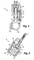
- Such a donor system has a housing which, as part of a master cylinder, includes a master piston cylinder and a master piston guided therein, which can be actuated by means of a hand lever.
- the donor system has filled with hydraulic fluid expansion tank as a reserve chamber and for a volume compensation during heating and cooling of the hydraulic fluid.
- the housing of the encoder system with reservoir is often produced by die casting or injection molding. The required mold must be designed according to the intended cavities in the encoder housing.
- known braking systems are Inner cavities and thereby arranged with the expansion tank in connection filling and venting arranged in the encoder housing, that these and outgoing therefrom connecting channels are difficult to produce for the expansion tank.
- Object of the present invention is to arrange at a brake system of the type mentioned in the filling and venting of the expansion tank and the subsequent connection channels so that on the one hand, a simple production of the encoder housing and associated parts is favored and on the other hand a simple and under Prevention of contamination of the environment with hydraulic fluid - non-pollutant - filling and bleeding of the brake system is possible.
- the filling and venting opening has a plug-in section arranged in a cover of the expansion tank for sealingly receiving a venting and filling tool, to which a connection chamber in the sensor housing adjoins in the insertion direction, which has a lateral boundary wall to the expansion tank and in that at least one edge-open overflow opening is provided as flow passage to the expansion tank in the boundary wall.
- the filling and venting opening is thus arranged in the region of the cover of the expansion tank and thus at the top of the encoder system, whereby a favorable position for filling and venting is given from the outset.
- the insertion section in the cover is a passage opening, which can be easily produced in the production of the cover in a mold by a complementarily shaped pin is.
- the connection chamber in the encoder housing can also be easily formed by a molding pin. Both sections of the filling and venting are expediently oriented in Entformungscardi of the mold, so that a trouble-free removal is possible.
- the open-edge overflow opening which is also oriented in Entformungscardi, contributes to a simple design of the mold. Complicated auxiliary devices in the mold are thus not required, so that a particularly cost-effective production of the parts is possible.
- the venting and filling tool is securely held after insertion and via the connection chamber and the overflow is easily a flow connection to the expansion tank available.
- the secure mounting of the venting and filling tool when emptying, filling and bleeding the hydraulic system ensures that no brake fluid or hydraulic fluid escapes and causes damage to vehicle parts or makes them useless. Also, a skin contact with hydraulic fluid is safely avoided. For the aforementioned reasons, a comparatively extensive, cumbersome to handle equipment is used for handling brake fluid during filling and venting that can cause problems for an untrained user.
- the insertion of the filling and venting opening for sealingly receiving a connecting piece of the venting and filling tool is formed, wherein the connecting piece protrudes into the connection chamber in the connection chamber and wherein the connection chamber clear Inner dimensions has, which are larger than the protruding part of the connecting piece.
- connection chamber is arranged in an oblique operating position of the correspondingly adjustable encoder system in a region lying deeper in the highest point of the lateral boundary wall.
- the connection chamber forms an air trap for air bubbles in the hydraulic fluid. These remain trapped by the deeper arrangement of the overflow in relation to the highest point of the interior of the connection chamber in this and can not get into the expansion tank and the other hydraulic circuit.
- two preferably oppositely arranged, open-top overflow openings may be provided in the boundary wall. These are then expediently positioned in each case offset to the highest point of the interior of the connection chamber by about 90 ° or more.
- the cover which covers the expansion tank and bears sealingly on the housing at the edge, has the insertion section for the venting and filling tool laterally next to the expansion tank and that the cup-shaped connection chamber adjoining in the insertion direction is located in the sensor housing.
- the filling and venting opening is located on the side next to the expansion tank, which is in an inclined filling and venting position in an elevated position, because on the one hand the venting is favored and on the other hand leakage of fluid when docking and undocking the venting and filling tool is avoided.
- connection chamber is arranged in the aforementioned embodiment in a projecting into the expansion tank bulge of the transmitter housing, so that the lateral boundary wall partially connects directly to the expansion tank.
- bulge side wall areas are provided in which the overflow openings spaced from the most projecting into the expansion tank wall area can be arranged.
- the filling and venting opening is arranged in the area of the lid covering the expansion tank, wherein the plug-in portion passes through the lid and wherein the connecting chamber in the plug housing in the plug-in direction in a housing projection located within the expansion tank located.
- This embodiment may be provided, inter alia be, if there is no space for the filling and venting opening laterally next to the expansion tank or the upper side sealing lid.
- the housing projection may extend in an island shape from the bottom of the expansion tank to the inside of the cover, wherein the connection chamber is located in the upper end and connects tightly to the insertion in the lid.
- the overflow or several overflow are also here in the upper edge of the connection chamber and are positioned so that in the operating position, where the encoder system obliquely, is lowered on one side, located in the connection chamber air bubbles do not pass through the overflow opening (s) in the expansion tank can.
- this is connected by means of a holder with a part of the bicycle, preferably the handlebar rotatably.
- the holder is designed for adjusting the encoder system at least on the one hand in a filling and venting position and on the other hand in an operating position. In the filling and venting position, the filling and venting opening is in the uppermost position of the hydraulic system.
- a seal is provided between the surge tank and the upper side sealing the lid, which extends into the region between the male and the adjoining connection chamber of the filling and venting opening.
- the seal is advantageously at least in Supporting area on the boundary wall of the connection chamber thickened, wherein the facing her, the insertion portion surrounding the cover area has an annular groove for sealingly receiving the seal or the thickened sealing region. Due to the thickening, the seal has an increased intrinsic stability, so that a good seal is also provided in the overlapping area of the seal above the open or open-ended overflow openings.
- an elastic bellows is used in the expansion tank, which is preferably formed by a rubber-elastic molded body and having at least one circumferential side flange as a seal between the surge tank and the lid.
- This bellows is used for volume compensation with changing filling volume of the hydraulic fluid in the expansion tank.
- the hydraulic system can thereby be formed closed to the outside.
- the elastic bellows is hollow and in particular trough-shaped with a circumferential, flange-like seal formed at the opening edge.
- the seal of the bellows in the assembly position forms the seal between the expansion tank and the cover, so that at the same time the bellows and the expansion tank are closed on the top side.
- a bellows vent opening is provided so that when volume changes of the hydraulic fluid in the expansion tank and corresponding change in volume of the bellows, located in the interior of the bellows escape air or can flow from the outside.
- the underside of the bellows at least in Filling and bleeding position of the donor system forms an inclined guide surface for venting at the filling and venting.
- air bubbles contained in the hydraulic fluid are guided in the direction of ventilation as the hydraulic fluid rises along the roof-shaped rising guide surface of the bellows, which promotes complete ventilation.
- For a clean (free of clogging) filling of the hydraulic system with hydraulic fluid has a brake system associated venting and filling a connection piece or the like connection element for sealing insertion into the filling and vent opening. This can be carried out essentially without further aids filling and / or venting of the hydraulic system.
- venting and filling tool can be inserted directly into the filling and venting opening or its insertion section and is then held in an approximately vertical or slightly oblique position. Additional aids for holding are not required.
- a conical connection between the connecting piece and filling and venting a tight and secure connection is alone by the insertion, which is pressure and vacuum tight and contributes to a simple and clean handling during filling and ventilation process.
- the connecting piece of the venting and filling tool has a Luerkonus or a Luer-Lock and if the filling and venting or their insertion is designed to match the connection piece.
- Both the Luerkonus for insertion and the Luer-Lock for screwing Build proven, easy-to-use, tight and secure connections.
- the venting and filling tool has a piston-cylinder arrangement. This ensures a particularly good metering of the hydraulic fluid to be filled. This is of particular importance in view of the small capacity, for example, in hydraulic brake systems for bicycles.
- both pressure and a comparatively high negative pressure can be generated, by which, apart from a flushing and a sucking filling of the hydraulic system is possible.
- Luerkonus or Luer-Lock cone compound When using a Luerkonus or Luer-Lock cone compound can be used in a particularly advantageous manner as a venting and filling a commercial syringe, which is practically everywhere available and inexpensive and their usual filling volume of, for example, 10 ml or 20 ml for a complete filling and / or venting a hydraulic system sufficient in particular for bicycles, without having to be on and off several times.
- the bleeding and filling tool can also be integrated in the encoder system, ie be part of the encoder system. It can be permanently connected to the expansion tank or held in a holder and removable for the filling and venting process or removable and can be tightly connected to the filling and venting.
- the overflow opening from the connection chamber to the expansion tank instead of in the boundary wall of the Connection chamber may be arranged in a resting on the boundary wall counterpart.
- the counterpart resting on the boundary wall may in particular be the cover or a seal between the cover and the expansion tank.
- the overflow opening (s) from the connection chamber to the expansion tank may in such a case be provided in the cover itself or in a seal between the cover and the expansion tank.
- the overflow opening (s) can be channel-shaped in their area covering the boundary wall as an open-edged groove which, with its opening, faces the boundary wall and overlaps it. It is preferably provided that the seal with the at least one overflow opening is the circumferential side flange of the elastic bellows.
- a hydraulic brake system 1 shown in FIG. 1 can be used in particular for bicycles, but possibly also for other two-wheelers. It has a donor system 2 and a braking device 4 attached to a brake disk 3.
- the brake system is filled with hydraulic fluid, wherein the encoder system 2 is connected via a dashed line indicated hydraulic line 5 to the brake device 4.
- the encoder system 2 has a hand-operated brake lever 6, with which a master piston 7 (see FIG. 2) guided in a cylinder 8 can be moved, thereby conveying hydraulic fluid via the hydraulic line 5 to the brake device 4.
- This brake device 4 has a brake caliper 36, which is arranged on the brake disc 3 connected to the wheel to be braked.
- the brake disk 3 is acted on both sides with two brake pads 9 during braking (FIG. 3).
- 10 brake pistons 11 are provided in brake cylinders, which are acted upon by hydraulic fluid on the back.
- the hydraulic fluid is thereby guided from the hydraulic line 5 via channels 12 to the pressure chambers 13 located behind the
- the encoder system 2 has a surge tank 14 for Hydraulic fluid, which is connected to the cylinder 8 and thus the hydraulic circuit with unconfirmed brake lever 6.
- the donor system 2 has a filling and venting opening 15 and the braking device 4 also has a filling and venting opening 16 (FIG. 3).
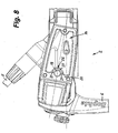
- the filling and venting opening 15 of the encoder system 2 is provided on the upper side thereof and passes through a cover 17 which closes the expansion tank 14 on the upper side (FIGS. 4 to 7), which is connected by screwing to the encoder housing 20.
- connection chamber 19 is pot-shaped or cup-shaped and has slit-shaped, open-ended overflow openings 21 to the expansion tank 14 at its upper edge. As a result, there is a flow connection between this connection chamber 19 and the expansion tank 14.
- the insertion portion 18 in the cover 17 and the connection chamber 19 in the encoder housing 20 are aligned with respect to their longitudinal axes so that they each extend in Entformungscardi the lid or the encoder housing and thus allow easy removal from the mold. Due to the open-edged design of the preferably slot-shaped overflow openings 21, which are also oriented in Entformungs therapies, they are also easy to produce.
- the plug-in section 18 of the filling and venting opening 15 is designed for sealingly receiving a connecting piece 22 of a venting and filling tool 23 and has a receiving cone 25 for this purpose.
- the receiving cone 25 is preferably designed for plug-in reception of a connecting piece 22 of the venting and filling tool 23 designed as a Luerkonus 24 (FIG. 6).
- the plug-in connection with the receiving cone 25 and the connecting piece 22 is dimensioned such that the connecting piece 22 partially protrudes into the connecting chamber 19 in the inserted position, wherein it still has some distance from the bottom of the connecting chamber 19 with its inner end, as is good in FIG is recognizable.
- the connecting piece 22 of the venting and filling tool 23 is securely held in the cover 17, so that unintentional slipping out is reliably prevented even during manipulation during a venting or filling operation.
- the connection chamber 19 has clear dimensions that are larger than those of the protruding part of the connecting piece 22, so that there is still room for an overflow of hydraulic fluid through the overflow openings 21.
- the filling and venting opening 15 is arranged laterally next to the expansion tank 14 and is in the filling and venting position according to FIG. 6 on the highest side next to the expansion tank 14.
- the cover 17 is designed so that it also this, laterally adjacent to the surge tank 14 area of the encoder housing 20 overlaps.
- connection chamber 19 of the filling and venting 15 in a laterally projecting into the surge tank 14 bulge 26 of the transmitter housing 20th is arranged.
- the connection chamber 19 is surrounded by a boundary wall 27, in which the two slot-shaped, upwardly open-edge overflow openings 21 are located.
- the two overflow openings 21 are arranged laterally offset from the foremost, the surge tank 14 facing region of the bulge 26. It is thereby achieved that, after a filling or venting process, air bubbles still present in the connection chamber 19 in the oblique operating position of the encoder system 2 shown in FIG.
- the overflow openings 21 are formed as narrow edge slots, wherein the slot width for retaining air bubbles contained in the hydraulic fluid is dimensioned.
- an elastic bellows 30 is used, which, as can be seen in Fig. 13, trough-shaped and has at its opening edge a circumferential, formed as a flange seal 31.
- This bellows 31 is inserted into the expansion tank 14 and fills this area.
- the seal 31 rests on the edge region of the expansion tank and thus on the encoder housing 20.
- the lid 17 is then a closing and sealing both the bellows 30 and the surge tank 14 to the outside.
- the cavity of the bellows 30 is connected through a bellows vent 32 ( Figures 1 and 10) through the lid 17 to the outside atmosphere.
- the seal 31 which is formed by the side flange of the bellows 30, extends into the side area adjacent to the surge tank 14 and thereby between the insertion portion 18 and the connection chamber 19 of the filling and Vent 15.
- the seal 31 is provided with a Ringwulst 33, as well in Figs. 6 and 13 can be seen.
- the lid portion surrounding the insertion portion 18 has an annular groove 34 for sealingly receiving this annular bead 33 (FIG. 12).
- the annular bead 33 rests with its lower side on the upper edge of the connection chamber 19 or its boundary wall 27 (FIG. 6).
- annular bead 33 The located in the boundary wall 27, open-edge overflow openings 21 are bridged by the annular bead 33, wherein the increased intrinsic stability of the annular bead 33 provides in comparison to the flat design of the seal in the adjacent area in the bridging region for a good tightness.
- the filling and venting opening 15 can be closed with an elastic sealing plug 35 (FIG. 5), preferably provided with a cone.
- the filling and venting opening 15 preferably has a plug-in section 18 with a receiving cone 25, into which the closure plug 35 provided with a matching outer cone can be inserted.
- the seal is made by the cone connection.
- the sealing plug 35 may have an externally accessible insertion cavity as a tool engagement point for a turning tool, which is preferably designed as a hexagon socket for a hexagon key as a turning tool.
- the closure plug 35 can thereby be slightly twisted after insertion of the rotary tool with this and thereby, supported by the cone connection, pulled out.
- the inserted sealing plug can be approximately flush with the outside of the lid or the opening of the Einsteckabêts 18 in the lid 17 or even slightly lower, so that accidental loosening or removal of the sealing plug is practically impossible.
- the closure plug can be made of hard plastic material, for example of the same material as the lid 17. Other materials are also possible, it being only necessary to ensure that the torque for rotating the closure plug 35 can be transmitted by the rotary tool.
- overflow openings 21a are arranged from the connection chamber to the expansion tank instead, as described above, in the boundary wall 27 of the connection chamber 19, in a counterpart resting on the boundary wall, which seal 31 between the cover and the surge tank as part of the bellows 30a.
- the seal 31 is formed by the circumferential side flange of the elastic bellows 30 a (FIGS. 15 and 16).
- This sealing or side flange extends over the region of the connection chamber 19 and its boundary wall 27, wherein in the exemplary embodiment, three channel-shaped overflow 21a (Fig.16) in the bellows side flange and thus the seal 31 are arranged and cover the boundary wall 27, so with their ends on the one hand into the expansion tank 14 and on the other hand into the connection chamber 19 protrude.
- the overflow openings 21a are formed as open-edged grooves, which face the boundary wall 27 with their openings.
- the seal 31 is thickened in the support area on the boundary wall 27 of the connection chamber 19 (FIG. 15), so that on the one hand an increased intrinsic stability is present in this area and, on the other hand, there is space for overflow openings 21a which are adequately dimensioned in cross section.
- the at least one overflow 21 may also be provided directly from the connection chamber 19 to the expansion tank 14 in the lid 17, if this is made of suitable material to achieve a seal to the connection chamber 19.
- the overflow openings are arranged at the corresponding location as in the seal 31.
- the at least one overflow opening could also be designed as a bore in the side wall of the connection chamber 19. In shaping processes such as injection molding, however, edge-open overflow openings are easier to realize in terms of injection technology.
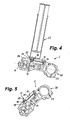
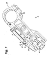
- the encoder system 2 can be connected by means of a holder 28 with the handlebar of a two-wheeler.
- the holder 28 is formed like a clamp and can be tightened or loosened by means of a clamping screw 29.
- the transmitter system can be adjusted easily to the appropriate position on the one hand for operation (FIGS. 5 and 7) and, correspondingly, for good operability and on the other hand for the filling and venting process (FIGS. 4 and 6).
- the donor system 2 from a position with nearly vertical venting and filling tool 23 as shown in FIGS. 4 and 6, to an approximately horizontal position of the venting and filling 23 well possible is.
- the syringe forming the venting and filling tool 23 can be attached to the top of the donor system 2 as shown in FIGS. 4, 6 and 9 and tightly inserted into the receiving cone 25 of the filling and venting opening 15 with its connecting piece 22.
- the intended cone connection results in a secure and tight connection even with slight impressions.
- the braking device 4 can be connected to the filling and venting opening 16 a container with hydraulic fluid, said container may also be filled with a hydraulic fluid syringe.
- the filling and vent opening 16 of the braking device 4 is also provided with a Luer receiving cone, so that here also commercially available syringes can be used as a venting and filling tool 23.
- the hydraulic fluid With the syringe attached above in the donor system 2, the hydraulic fluid is sucked in and then flows from below into the hydraulic system. The lower, filled with hydraulic fluid syringe can be assisted, so that the filling process can be completed quickly.
Landscapes
- Engineering & Computer Science (AREA)
- Mechanical Engineering (AREA)
- Transportation (AREA)
- Physics & Mathematics (AREA)
- Fluid Mechanics (AREA)
- Transmission Of Braking Force In Braking Systems (AREA)
- Valves And Accessory Devices For Braking Systems (AREA)
- Valve Device For Special Equipments (AREA)
- Braking Systems And Boosters (AREA)
- Supply Devices, Intensifiers, Converters, And Telemotors (AREA)
- Braking Arrangements (AREA)
Priority Applications (1)
| Application Number | Priority Date | Filing Date | Title |
|---|---|---|---|
| PL07016148T PL1894831T3 (pl) | 2006-08-29 | 2007-08-17 | Układ hamulcowy z hydrauliczną instalacją hamulcową |
Applications Claiming Priority (1)
| Application Number | Priority Date | Filing Date | Title |
|---|---|---|---|
| DE102006040327A DE102006040327A1 (de) | 2006-08-29 | 2006-08-29 | Bremssystem mit einer hydraulischen Bremsanlage |
Publications (3)
| Publication Number | Publication Date |
|---|---|
| EP1894831A2 true EP1894831A2 (fr) | 2008-03-05 |
| EP1894831A3 EP1894831A3 (fr) | 2008-10-08 |
| EP1894831B1 EP1894831B1 (fr) | 2009-11-11 |
Family
ID=38487119
Family Applications (1)
| Application Number | Title | Priority Date | Filing Date |
|---|---|---|---|
| EP07016148A Active EP1894831B1 (fr) | 2006-08-29 | 2007-08-17 | Dispositif de freinage avec un système hydraulique de freinage |
Country Status (6)
| Country | Link |
|---|---|
| US (1) | US20080053758A1 (fr) |
| EP (1) | EP1894831B1 (fr) |
| AT (1) | ATE448136T1 (fr) |
| DE (2) | DE102006040327A1 (fr) |
| PL (1) | PL1894831T3 (fr) |
| TW (1) | TW200831346A (fr) |
Cited By (1)
| Publication number | Priority date | Publication date | Assignee | Title |
|---|---|---|---|---|
| WO2012127014A1 (fr) * | 2011-03-24 | 2012-09-27 | Continental Teves Ag & Co. Ohg | Contenant de fluide hydraulique pour un système de freinage hydraulique d'automobile et procédé de remplissage |
Families Citing this family (11)
| Publication number | Priority date | Publication date | Assignee | Title |
|---|---|---|---|---|
| DE102006040328A1 (de) * | 2006-08-29 | 2008-03-06 | Gustav Magenwirth Gmbh & Co. Kg | Bremssystem mit einer hydraulischen Bremsanlage |
| US7832531B2 (en) * | 2009-03-06 | 2010-11-16 | Shimano Inc. | Bicycle component fixing band |
| DE102009039620A1 (de) | 2009-09-01 | 2011-03-03 | Gustav Magenwirth Gmbh & Co. Kg | Gebervorrichtung für ein geschlossenes Hydrauliksystem lenkergeführter Fahrzeuge |
| IT1402323B1 (it) * | 2010-09-16 | 2013-08-30 | Formula Srl | Corpo pompa per il comando di attuatori idraulici di freni a disco per biciclette e motociclette |
| USD641670S1 (en) | 2010-11-24 | 2011-07-19 | Hb Performance Systems, Inc. | Brake pad |
| US8943924B2 (en) | 2010-11-24 | 2015-02-03 | Hb Performance Systems, Inc. | System and method for an adjustable lever assembly |
| DE102011075186A1 (de) * | 2011-05-03 | 2012-11-08 | Gustav Magenwirth Gmbh & Co. Kg | Geber für ein hydraulisches Betätigungselement |
| US9688348B2 (en) * | 2014-12-15 | 2017-06-27 | Shimano Inc. | Hydraulic hose fitting and hydraulic device |
| IT201600103768A1 (it) | 2016-10-17 | 2018-04-17 | Campagnolo Srl | Valvola di spurgo per impianto frenante idraulico di bicicletta |
| DE112019007910T5 (de) * | 2019-11-22 | 2022-09-08 | Schaeffler Technologies AG & Co. KG | Hydraulikzylinder-Entlüftungsmechanismus und hydraulischer Aktuator einer hydraulischen Parksperre |
| US12037076B1 (en) * | 2023-03-09 | 2024-07-16 | Shimano Inc. | Hydraulic reservoir and operating device of human-powered vehicle |
Citations (1)
| Publication number | Priority date | Publication date | Assignee | Title |
|---|---|---|---|---|
| US6298961B1 (en) | 2000-03-02 | 2001-10-09 | Delphi Technologies, Inc. | Reservoir cap and bleed mechanism |
Family Cites Families (25)
| Publication number | Priority date | Publication date | Assignee | Title |
|---|---|---|---|---|
| US2316497A (en) * | 1941-10-28 | 1943-04-13 | Du Pont | Hydraulically actuated system |
| US4170280A (en) * | 1978-03-14 | 1979-10-09 | Parker-Hannifin Corporation | Bleeder harness for brake master cylinders |
| US4201056A (en) * | 1978-05-01 | 1980-05-06 | Kent-Moore Corporation | Brake bleeder adapter |
| US4236549A (en) * | 1978-05-12 | 1980-12-02 | Autoline Supply Company | Bleeder kit for bleeding a master cylinder |
| US4306639A (en) * | 1980-06-13 | 1981-12-22 | General Motors Corporation | Disc brake caliper with molded flex piston |
| US4788821A (en) * | 1983-11-28 | 1988-12-06 | Automotive Products, Plc | Hydraulic shift for motor vehicle transmission |
| GB8602486D0 (en) * | 1986-01-31 | 1986-03-05 | Liquid Levers Ltd | Fluid system bleeding apparatus |
| US4785629A (en) * | 1987-06-04 | 1988-11-22 | Ennis Iii James F | Syringe-dispensed brake fluid for filling and purging master cylinder circuit from slave |
| FR2631937B1 (fr) * | 1988-05-31 | 1990-09-14 | Bendix France | |
| US5088529A (en) * | 1990-08-27 | 1992-02-18 | General Motors Corporation | Vehicle brake vacuum evacuation and brake fluid fill machine |
| AU635631B2 (en) * | 1991-01-15 | 1993-03-25 | Astra Pharmaceuticals Pty Ltd | Plastic syringe |
| US5324082A (en) * | 1991-08-29 | 1994-06-28 | Bundy Corporation | Positive transition quick connect coupling |
| US5497864A (en) * | 1995-06-20 | 1996-03-12 | Chrysler Corporation | Hydraulic brake bleeder apparatus |
| KR0120417B1 (en) * | 1995-07-19 | 1997-11-04 | Hyundai Motor Co Ltd | Oil-compensating device for brake device |
| DE19648050B4 (de) * | 1995-11-28 | 2006-03-09 | Honda Giken Kogyo K.K. | Hydraulikdruckquelleneinrichtung und Fahrzeughöhen-Steuer/Regel-Einrichtung |
| DE19639560A1 (de) * | 1996-09-26 | 1998-04-02 | Bosch Gmbh Robert | Hydraulische Fahrzeugbremsanlage |
| US5950772A (en) * | 1997-08-29 | 1999-09-14 | Hayes Brake, Inc. | Bicycle brake system having a flexible disk |
| US5967199A (en) * | 1998-05-13 | 1999-10-19 | General Motors Corporation | Pressurized brake bleed system |
| JP4965058B2 (ja) * | 2000-11-30 | 2012-07-04 | フレニ・ブレンボ エス・ピー・エー | ハンドルバーによって制御可能な車両用のマスターシリンダー |
| US6871729B2 (en) * | 2001-03-02 | 2005-03-29 | Freni Brembo S.P.A. | Master cylinder for a brake or clutch of a motorcycle or bike |
| DE20108558U1 (de) * | 2001-05-22 | 2001-08-09 | Krebs, Peter, Dr., 78048 Villingen-Schwenningen | Kombinationsnadel für die peripheren Nervenblockaden |
| US6581905B2 (en) * | 2001-11-21 | 2003-06-24 | Tenneco Automotive Inc. | Brake bleed tool |
| EP1525418B1 (fr) * | 2002-07-31 | 2008-05-07 | Dynamic Fluid Control (PTY) Ltd | Soupape d'evacuation d'air |
| RU2442213C2 (ru) * | 2006-06-13 | 2012-02-10 | Майкрософт Корпорейшн | Панель управления поисковым механизмом |
| DE102006040328A1 (de) * | 2006-08-29 | 2008-03-06 | Gustav Magenwirth Gmbh & Co. Kg | Bremssystem mit einer hydraulischen Bremsanlage |
-
2006
- 2006-08-29 DE DE102006040327A patent/DE102006040327A1/de not_active Withdrawn
-
2007
- 2007-08-17 DE DE502007001952T patent/DE502007001952D1/de active Active
- 2007-08-17 EP EP07016148A patent/EP1894831B1/fr active Active
- 2007-08-17 AT AT07016148T patent/ATE448136T1/de active
- 2007-08-17 PL PL07016148T patent/PL1894831T3/pl unknown
- 2007-08-22 TW TW096131008A patent/TW200831346A/zh unknown
- 2007-08-29 US US11/846,584 patent/US20080053758A1/en not_active Abandoned
Patent Citations (1)
| Publication number | Priority date | Publication date | Assignee | Title |
|---|---|---|---|---|
| US6298961B1 (en) | 2000-03-02 | 2001-10-09 | Delphi Technologies, Inc. | Reservoir cap and bleed mechanism |
Cited By (4)
| Publication number | Priority date | Publication date | Assignee | Title |
|---|---|---|---|---|
| WO2012127014A1 (fr) * | 2011-03-24 | 2012-09-27 | Continental Teves Ag & Co. Ohg | Contenant de fluide hydraulique pour un système de freinage hydraulique d'automobile et procédé de remplissage |
| CN103562030A (zh) * | 2011-03-24 | 2014-02-05 | 大陆-特韦斯贸易合伙股份公司及两合公司 | 用于机动车液压制动装置的压力介质容器及加注方法 |
| US8904783B2 (en) | 2011-03-24 | 2014-12-09 | Continental Teves Ag & Co. Ohg | Pressure medium container for a hydraulic motor vehicle brake system and method for filling |
| CN103562030B (zh) * | 2011-03-24 | 2016-04-27 | 大陆-特韦斯贸易合伙股份公司及两合公司 | 用于机动车液压制动装置的压力介质容器及加注方法 |
Also Published As
| Publication number | Publication date |
|---|---|
| EP1894831A3 (fr) | 2008-10-08 |
| ATE448136T1 (de) | 2009-11-15 |
| US20080053758A1 (en) | 2008-03-06 |
| DE102006040327A1 (de) | 2008-03-06 |
| PL1894831T3 (pl) | 2010-04-30 |
| TW200831346A (en) | 2008-08-01 |
| EP1894831B1 (fr) | 2009-11-11 |
| DE502007001952D1 (de) | 2009-12-24 |
Similar Documents
| Publication | Publication Date | Title |
|---|---|---|
| EP1894831B1 (fr) | Dispositif de freinage avec un système hydraulique de freinage | |
| EP1908659B1 (fr) | Système de freinage doté d'une installation de freinage hydraulique | |
| DE2615986C2 (de) | Verfahren zur Herstellung einer hydraulischen Ausrückvorrichtung und hydraulische Ausrückvorrichtung für Reibkupplungen | |
| DE2946765C2 (de) | Entsperrbares Rückschlagventil | |
| DE202013012255U1 (de) | Hydraulischer Bremsmechanismus | |
| DE3309916A1 (de) | Saug- und spuelvorrichtung | |
| DE3036076A1 (de) | Ausspuel- und absaughandstueck | |
| EP0758540A2 (fr) | Pièce à main médical à turbine, in particulier pour applications dentaires | |
| DE3324631C2 (fr) | ||
| DE102011078153A1 (de) | Hydraulikkonverter und hydraulische Bremse | |
| DE102017104155B4 (de) | Einwegventil-Baugruppe | |
| DE4031613C2 (de) | Dialysegerät | |
| WO2008028800A1 (fr) | Dispositif de repassage à vapeur à élément d'accès arrière | |
| DE102007035386B4 (de) | Entlüftungsvorrichtung | |
| DE60029623T2 (de) | Einheit für mikrobiologische prüfung einer flüssigen probe unter druck und verfharen für das leeren dieser einheit | |
| EP4214098B1 (fr) | Armature hydraulique | |
| DE3309917A1 (de) | Ventil | |
| EP1893459B1 (fr) | Vis d'evacuation d'air a soupape de non-retour | |
| DE60307947T2 (de) | Hydraulisches Bremsventil und Verfahren zum Entlüften eines hydraulischen Bremssystems | |
| DE19802601C2 (de) | Kopfstruktur für eine Luftpumpe | |
| WO2014023500A1 (fr) | Procédé de fabrication d'un dispositif de raccordement destiné à être utilisé dans le traitement de plaies par une pression négative | |
| DE202006011061U1 (de) | Entlüftungsschraube mit Rückschlagventil | |
| EP2283909A1 (fr) | Dispositif de filtre à huile doté d'un dispositif de déshuilage | |
| WO2018210703A1 (fr) | Dispositif de commande de frein pour système de freinage de véhicule | |
| DE102008003740A1 (de) | Vorrichtung zur Ventilbetätigung |
Legal Events
| Date | Code | Title | Description |
|---|---|---|---|
| PUAI | Public reference made under article 153(3) epc to a published international application that has entered the european phase |
Free format text: ORIGINAL CODE: 0009012 |
|
| AK | Designated contracting states |
Kind code of ref document: A2 Designated state(s): AT BE BG CH CY CZ DE DK EE ES FI FR GB GR HU IE IS IT LI LT LU LV MC MT NL PL PT RO SE SI SK TR |
|
| AX | Request for extension of the european patent |
Extension state: AL BA HR MK YU |
|
| PUAL | Search report despatched |
Free format text: ORIGINAL CODE: 0009013 |
|
| AK | Designated contracting states |
Kind code of ref document: A3 Designated state(s): AT BE BG CH CY CZ DE DK EE ES FI FR GB GR HU IE IS IT LI LT LU LV MC MT NL PL PT RO SE SI SK TR |
|
| AX | Request for extension of the european patent |
Extension state: AL BA HR MK RS |
|
| RIC1 | Information provided on ipc code assigned before grant |
Ipc: B60T 11/26 20060101ALI20080904BHEP Ipc: B62L 3/02 20060101AFI20070924BHEP Ipc: B60K 15/04 20060101ALI20080904BHEP Ipc: B60T 11/232 20060101ALI20080904BHEP Ipc: F16D 65/14 20060101ALI20080904BHEP |
|
| 17P | Request for examination filed |
Effective date: 20090326 |
|
| GRAP | Despatch of communication of intention to grant a patent |
Free format text: ORIGINAL CODE: EPIDOSNIGR1 |
|
| AKX | Designation fees paid |
Designated state(s): AT BE BG CH CY CZ DE DK EE ES FI FR GB GR HU IE IS IT LI LT LU LV MC MT NL PL PT RO SE SI SK TR |
|
| GRAS | Grant fee paid |
Free format text: ORIGINAL CODE: EPIDOSNIGR3 |
|
| GRAA | (expected) grant |
Free format text: ORIGINAL CODE: 0009210 |
|
| AK | Designated contracting states |
Kind code of ref document: B1 Designated state(s): AT BE BG CH CY CZ DE DK EE ES FI FR GB GR HU IE IS IT LI LT LU LV MC MT NL PL PT RO SE SI SK TR |
|
| REG | Reference to a national code |
Ref country code: GB Ref legal event code: FG4D Free format text: NOT ENGLISH |
|
| REG | Reference to a national code |
Ref country code: CH Ref legal event code: EP |
|
| REG | Reference to a national code |
Ref country code: IE Ref legal event code: FG4D |
|
| REF | Corresponds to: |
Ref document number: 502007001952 Country of ref document: DE Date of ref document: 20091224 Kind code of ref document: P |
|
| REG | Reference to a national code |
Ref country code: CH Ref legal event code: NV Representative=s name: HANS RUDOLF GACHNANG PATENTANWALT |
|
| LTIE | Lt: invalidation of european patent or patent extension |
Effective date: 20091111 |
|
| PG25 | Lapsed in a contracting state [announced via postgrant information from national office to epo] |
Ref country code: PT Free format text: LAPSE BECAUSE OF FAILURE TO SUBMIT A TRANSLATION OF THE DESCRIPTION OR TO PAY THE FEE WITHIN THE PRESCRIBED TIME-LIMIT Effective date: 20100311 Ref country code: SE Free format text: LAPSE BECAUSE OF FAILURE TO SUBMIT A TRANSLATION OF THE DESCRIPTION OR TO PAY THE FEE WITHIN THE PRESCRIBED TIME-LIMIT Effective date: 20091111 Ref country code: IS Free format text: LAPSE BECAUSE OF FAILURE TO SUBMIT A TRANSLATION OF THE DESCRIPTION OR TO PAY THE FEE WITHIN THE PRESCRIBED TIME-LIMIT Effective date: 20100311 Ref country code: ES Free format text: LAPSE BECAUSE OF FAILURE TO SUBMIT A TRANSLATION OF THE DESCRIPTION OR TO PAY THE FEE WITHIN THE PRESCRIBED TIME-LIMIT Effective date: 20100222 Ref country code: FI Free format text: LAPSE BECAUSE OF FAILURE TO SUBMIT A TRANSLATION OF THE DESCRIPTION OR TO PAY THE FEE WITHIN THE PRESCRIBED TIME-LIMIT Effective date: 20091111 Ref country code: LT Free format text: LAPSE BECAUSE OF FAILURE TO SUBMIT A TRANSLATION OF THE DESCRIPTION OR TO PAY THE FEE WITHIN THE PRESCRIBED TIME-LIMIT Effective date: 20091111 |
|
| REG | Reference to a national code |
Ref country code: PL Ref legal event code: T3 |
|
| PG25 | Lapsed in a contracting state [announced via postgrant information from national office to epo] |
Ref country code: SI Free format text: LAPSE BECAUSE OF FAILURE TO SUBMIT A TRANSLATION OF THE DESCRIPTION OR TO PAY THE FEE WITHIN THE PRESCRIBED TIME-LIMIT Effective date: 20091111 Ref country code: LV Free format text: LAPSE BECAUSE OF FAILURE TO SUBMIT A TRANSLATION OF THE DESCRIPTION OR TO PAY THE FEE WITHIN THE PRESCRIBED TIME-LIMIT Effective date: 20091111 Ref country code: CY Free format text: LAPSE BECAUSE OF FAILURE TO SUBMIT A TRANSLATION OF THE DESCRIPTION OR TO PAY THE FEE WITHIN THE PRESCRIBED TIME-LIMIT Effective date: 20091111 |
|
| REG | Reference to a national code |
Ref country code: IE Ref legal event code: FD4D |
|
| PG25 | Lapsed in a contracting state [announced via postgrant information from national office to epo] |
Ref country code: IE Free format text: LAPSE BECAUSE OF FAILURE TO SUBMIT A TRANSLATION OF THE DESCRIPTION OR TO PAY THE FEE WITHIN THE PRESCRIBED TIME-LIMIT Effective date: 20091111 Ref country code: EE Free format text: LAPSE BECAUSE OF FAILURE TO SUBMIT A TRANSLATION OF THE DESCRIPTION OR TO PAY THE FEE WITHIN THE PRESCRIBED TIME-LIMIT Effective date: 20091111 Ref country code: DK Free format text: LAPSE BECAUSE OF FAILURE TO SUBMIT A TRANSLATION OF THE DESCRIPTION OR TO PAY THE FEE WITHIN THE PRESCRIBED TIME-LIMIT Effective date: 20091111 Ref country code: BG Free format text: LAPSE BECAUSE OF FAILURE TO SUBMIT A TRANSLATION OF THE DESCRIPTION OR TO PAY THE FEE WITHIN THE PRESCRIBED TIME-LIMIT Effective date: 20100211 Ref country code: RO Free format text: LAPSE BECAUSE OF FAILURE TO SUBMIT A TRANSLATION OF THE DESCRIPTION OR TO PAY THE FEE WITHIN THE PRESCRIBED TIME-LIMIT Effective date: 20091111 |
|
| PG25 | Lapsed in a contracting state [announced via postgrant information from national office to epo] |
Ref country code: CZ Free format text: LAPSE BECAUSE OF FAILURE TO SUBMIT A TRANSLATION OF THE DESCRIPTION OR TO PAY THE FEE WITHIN THE PRESCRIBED TIME-LIMIT Effective date: 20091111 Ref country code: SK Free format text: LAPSE BECAUSE OF FAILURE TO SUBMIT A TRANSLATION OF THE DESCRIPTION OR TO PAY THE FEE WITHIN THE PRESCRIBED TIME-LIMIT Effective date: 20091111 |
|
| PLBE | No opposition filed within time limit |
Free format text: ORIGINAL CODE: 0009261 |
|
| STAA | Information on the status of an ep patent application or granted ep patent |
Free format text: STATUS: NO OPPOSITION FILED WITHIN TIME LIMIT |
|
| 26N | No opposition filed |
Effective date: 20100812 |
|
| PG25 | Lapsed in a contracting state [announced via postgrant information from national office to epo] |
Ref country code: GR Free format text: LAPSE BECAUSE OF FAILURE TO SUBMIT A TRANSLATION OF THE DESCRIPTION OR TO PAY THE FEE WITHIN THE PRESCRIBED TIME-LIMIT Effective date: 20100212 |
|
| BERE | Be: lapsed |
Owner name: GUSTAV MAGENWIRTH G.M.B.H. & CO. KG Effective date: 20100831 |
|
| PG25 | Lapsed in a contracting state [announced via postgrant information from national office to epo] |
Ref country code: MC Free format text: LAPSE BECAUSE OF NON-PAYMENT OF DUE FEES Effective date: 20100831 |
|
| PG25 | Lapsed in a contracting state [announced via postgrant information from national office to epo] |
Ref country code: BE Free format text: LAPSE BECAUSE OF NON-PAYMENT OF DUE FEES Effective date: 20100831 |
|
| PGFP | Annual fee paid to national office [announced via postgrant information from national office to epo] |
Ref country code: CH Payment date: 20110824 Year of fee payment: 5 |
|
| PGFP | Annual fee paid to national office [announced via postgrant information from national office to epo] |
Ref country code: GB Payment date: 20110824 Year of fee payment: 5 Ref country code: PL Payment date: 20110901 Year of fee payment: 5 |
|
| REG | Reference to a national code |
Ref country code: DE Ref legal event code: R082 Ref document number: 502007001952 Country of ref document: DE |
|
| PG25 | Lapsed in a contracting state [announced via postgrant information from national office to epo] |
Ref country code: MT Free format text: LAPSE BECAUSE OF FAILURE TO SUBMIT A TRANSLATION OF THE DESCRIPTION OR TO PAY THE FEE WITHIN THE PRESCRIBED TIME-LIMIT Effective date: 20091111 |
|
| PGFP | Annual fee paid to national office [announced via postgrant information from national office to epo] |
Ref country code: NL Payment date: 20110825 Year of fee payment: 5 |
|
| PG25 | Lapsed in a contracting state [announced via postgrant information from national office to epo] |
Ref country code: LU Free format text: LAPSE BECAUSE OF NON-PAYMENT OF DUE FEES Effective date: 20100817 Ref country code: HU Free format text: LAPSE BECAUSE OF FAILURE TO SUBMIT A TRANSLATION OF THE DESCRIPTION OR TO PAY THE FEE WITHIN THE PRESCRIBED TIME-LIMIT Effective date: 20100512 |
|
| PG25 | Lapsed in a contracting state [announced via postgrant information from national office to epo] |
Ref country code: TR Free format text: LAPSE BECAUSE OF FAILURE TO SUBMIT A TRANSLATION OF THE DESCRIPTION OR TO PAY THE FEE WITHIN THE PRESCRIBED TIME-LIMIT Effective date: 20091111 |
|
| REG | Reference to a national code |
Ref country code: NL Ref legal event code: V1 Effective date: 20130301 |
|
| REG | Reference to a national code |
Ref country code: CH Ref legal event code: PL |
|
| GBPC | Gb: european patent ceased through non-payment of renewal fee |
Effective date: 20120817 |
|
| PG25 | Lapsed in a contracting state [announced via postgrant information from national office to epo] |
Ref country code: NL Free format text: LAPSE BECAUSE OF NON-PAYMENT OF DUE FEES Effective date: 20130301 Ref country code: CH Free format text: LAPSE BECAUSE OF NON-PAYMENT OF DUE FEES Effective date: 20120831 Ref country code: LI Free format text: LAPSE BECAUSE OF NON-PAYMENT OF DUE FEES Effective date: 20120831 |
|
| PG25 | Lapsed in a contracting state [announced via postgrant information from national office to epo] |
Ref country code: GB Free format text: LAPSE BECAUSE OF NON-PAYMENT OF DUE FEES Effective date: 20120817 |
|
| REG | Reference to a national code |
Ref country code: AT Ref legal event code: MM01 Ref document number: 448136 Country of ref document: AT Kind code of ref document: T Effective date: 20120831 |
|
| PG25 | Lapsed in a contracting state [announced via postgrant information from national office to epo] |
Ref country code: AT Free format text: LAPSE BECAUSE OF NON-PAYMENT OF DUE FEES Effective date: 20120831 |
|
| PG25 | Lapsed in a contracting state [announced via postgrant information from national office to epo] |
Ref country code: PL Free format text: LAPSE BECAUSE OF NON-PAYMENT OF DUE FEES Effective date: 20120817 |
|
| REG | Reference to a national code |
Ref country code: PL Ref legal event code: LAPE |
|
| REG | Reference to a national code |
Ref country code: FR Ref legal event code: PLFP Year of fee payment: 10 |
|
| REG | Reference to a national code |
Ref country code: FR Ref legal event code: PLFP Year of fee payment: 11 |
|
| REG | Reference to a national code |
Ref country code: FR Ref legal event code: PLFP Year of fee payment: 12 |
|
| PGFP | Annual fee paid to national office [announced via postgrant information from national office to epo] |
Ref country code: DE Payment date: 20240819 Year of fee payment: 18 |
|
| PGFP | Annual fee paid to national office [announced via postgrant information from national office to epo] |
Ref country code: FR Payment date: 20240823 Year of fee payment: 18 |
|
| PGFP | Annual fee paid to national office [announced via postgrant information from national office to epo] |
Ref country code: IT Payment date: 20240827 Year of fee payment: 18 |
|
| REG | Reference to a national code |
Ref country code: DE Ref legal event code: R119 Ref document number: 502007001952 Country of ref document: DE |