EP1895209A1 - Joint mécanique - Google Patents
Joint mécanique Download PDFInfo
- Publication number
- EP1895209A1 EP1895209A1 EP06766693A EP06766693A EP1895209A1 EP 1895209 A1 EP1895209 A1 EP 1895209A1 EP 06766693 A EP06766693 A EP 06766693A EP 06766693 A EP06766693 A EP 06766693A EP 1895209 A1 EP1895209 A1 EP 1895209A1
- Authority
- EP
- European Patent Office
- Prior art keywords
- seal
- circumferential surface
- bellows
- inner circumferential
- ring
- Prior art date
- Legal status (The legal status is an assumption and is not a legal conclusion. Google has not performed a legal analysis and makes no representation as to the accuracy of the status listed.)
- Granted
Links
Images


Classifications
-
- F—MECHANICAL ENGINEERING; LIGHTING; HEATING; WEAPONS; BLASTING
- F16—ENGINEERING ELEMENTS AND UNITS; GENERAL MEASURES FOR PRODUCING AND MAINTAINING EFFECTIVE FUNCTIONING OF MACHINES OR INSTALLATIONS; THERMAL INSULATION IN GENERAL
- F16J—PISTONS; CYLINDERS; SEALINGS
- F16J15/00—Sealings
- F16J15/16—Sealings between relatively-moving surfaces
- F16J15/34—Sealings between relatively-moving surfaces with slip-ring pressed against a more or less radial face on one member
- F16J15/3404—Sealings between relatively-moving surfaces with slip-ring pressed against a more or less radial face on one member and characterised by parts or details relating to lubrication, cooling or venting of the seal
-
- F—MECHANICAL ENGINEERING; LIGHTING; HEATING; WEAPONS; BLASTING
- F16—ENGINEERING ELEMENTS AND UNITS; GENERAL MEASURES FOR PRODUCING AND MAINTAINING EFFECTIVE FUNCTIONING OF MACHINES OR INSTALLATIONS; THERMAL INSULATION IN GENERAL
- F16J—PISTONS; CYLINDERS; SEALINGS
- F16J15/00—Sealings
- F16J15/16—Sealings between relatively-moving surfaces
- F16J15/34—Sealings between relatively-moving surfaces with slip-ring pressed against a more or less radial face on one member
- F16J15/3464—Mounting of the seal
- F16J15/3476—Means for minimising vibrations of the slip-ring
-
- F—MECHANICAL ENGINEERING; LIGHTING; HEATING; WEAPONS; BLASTING
- F16—ENGINEERING ELEMENTS AND UNITS; GENERAL MEASURES FOR PRODUCING AND MAINTAINING EFFECTIVE FUNCTIONING OF MACHINES OR INSTALLATIONS; THERMAL INSULATION IN GENERAL
- F16J—PISTONS; CYLINDERS; SEALINGS
- F16J15/00—Sealings
- F16J15/16—Sealings between relatively-moving surfaces
- F16J15/34—Sealings between relatively-moving surfaces with slip-ring pressed against a more or less radial face on one member
- F16J15/3464—Mounting of the seal
- F16J15/348—Pre-assembled seals, e.g. cartridge seals
-
- F—MECHANICAL ENGINEERING; LIGHTING; HEATING; WEAPONS; BLASTING
- F16—ENGINEERING ELEMENTS AND UNITS; GENERAL MEASURES FOR PRODUCING AND MAINTAINING EFFECTIVE FUNCTIONING OF MACHINES OR INSTALLATIONS; THERMAL INSULATION IN GENERAL
- F16J—PISTONS; CYLINDERS; SEALINGS
- F16J15/00—Sealings
- F16J15/16—Sealings between relatively-moving surfaces
- F16J15/34—Sealings between relatively-moving surfaces with slip-ring pressed against a more or less radial face on one member
- F16J15/36—Sealings between relatively-moving surfaces with slip-ring pressed against a more or less radial face on one member connected by a diaphragm or bellow to the other member
- F16J15/363—Sealings between relatively-moving surfaces with slip-ring pressed against a more or less radial face on one member connected by a diaphragm or bellow to the other member the diaphragm or bellow being made of metal
Definitions
- the present invention relates generally to a mechanical seal device in which construction thereof is straightforward and a freely moveable one of a pair of seal rings thereof is able to operate as desired, and more particularly, a mechanical seal device of cartridge type which is suitable for sealing a sealed fluid with high viscosity, a sealed fluid containing slurry, a chemical fluid as sealed fluid and the like, and is able to predict solid matters in the sealed fluid from getting caught between the slide surfaces of the pair of seal rings or to predict occurrence of malfunction due to loading between the seal members.
- FIG. 4 illustrates a full cross section of a mechanical: seal device 100 which is installed in a casing 160.
- the mechanical sea device 100 is utilized as a shaft seal apparatus of a pump which operates with chemical liquid and the like.
- this mechanical seal device 100 provides a seal between the casing 160 and a rotary shaft 150 which extends through within a bore diameter surface 160A (inboard "A") of the casing 160. Also the mechanical seal device 100 is provided in a cartridge type so as to be mounted on the end surface 160B of the casing 160 for easy installation.
- the mechanical seal device 100 includes a stationary seal ring 102 and a rotary seal ring 112 which are disposed within the bore diameter surface 160A.
- primary constitution members include a casing main body 130 and a sleeve 125 in which the casing body 130 retains the stationary seal ring (axially displaceable seal ring) 102 and retainer 106 thereof in the outboard "B" in relation to the casing 160 and the sleeve 125 retains the rotary seal ring 112 within the bore diameter surface 160A with which the rotary shaft 150 fittingly mates with a clearance gap formed therebetween.
- the rotary seal ring 112 is mounted on one end portion located at the inboard "A" side of a long sleeve 125 in order to be disposed in the inboard "A” in relation to the bore diameter surface 160A of the casing 160.
- the other end portion of the sleeve 125 at the outboard "B" side is securely attached to a retainer portion 127 while a screw socket 128 in the retainer portion 127 is fastened so as to fix the retainer portion 127 with the rotary shaft 150.
- the coupling of the rotary seal ring 112 and the sleeve 125 is realized by means of a coupling element 126.
- Respective fit clearances between the rotary shaft 150 and sleeve 125 and between the sleeve 125 and coupling member 126 dispose O-rings for sealing the clearances.
- the sleeve 125 and the coupling member 126 are coupled by means of a drive pin 129 so as to rotate together.
- the coupling member 126 and the rotary seal ring 112 are coupled in a jointly rotatable relation by means of the drive pins locking in the U-shaped grooves 112A.
- the fit clearance between the coupling member 126 and the rotary seal ring 112 is provided a seal by 0-ring 141.
- the stationary seal ring 102 is securely attached to the annular surface with a step shoulder which is disposed at one end portion of the cylindrical retainer body 106.
- the retainer body 106 is retained in a non-rotatable manner while being freely moveable in the axial direction by means of a locking engagement between a fixation pin 137 disposed in the casing main body 130 and a long groove 106G disposed in the retainer body 106.
- the fit clearance between the retainer body 106 and the casing main body 130 which are freely moveable relative to each other is provided a seal by means of an O-ring 143 which is mounted between a first step shoulder surface 106A of the retainer body 106 and a second step shoulder surface 130A of the casing main body 130.
- the other end portion of the retainer body 106 fittingly receives and fixates a spring receiving portion.
- End portion 130F of the casing main body 130 forms a contact with an end surface 160B of the casing 160 while the casing main body 130 is fixed to the casing 160 by means of stud bolts 128B anchored to the casing 160 with nuts 128A fastened.
- a spring seat member 107 is installed in the first step shoulder surface by means of set screw portion.
- a spring supported by the spring seat member 107 is disposed between the spring seat member 107 and a spring receiving portion.
- the stationary seal ring 102' is resiliently urged by, the spring 120 by way of the spring receiving portion and the retainer body 106.
- the seal surface 102F of the stationary seal surface 102 urged by the spring 120 forms a seal-tight contact with the seal surface 112F of the rotary seal ring 112 for sealing a sealed fluid.
- a flushing passage 136 and a quenching passage 135 extend in a communicating manner from the outer circumferential surface of the casing main body 130 to inner circumferential surface thereof in which the flushing passage 136 passes outer circumferential side of the rotary seal ring 112 and the stationary seal ring 102 while the quenching passage 135 passes inner circumferential surfaces of the rotary seal ring 112 and the stationary seal ring 102. Then the flushing passage 136 permits flushing fluid while the quenching passage 135 permits quenching fluid.
- a mechanical seal device 100 thus configured which is required to dispose the rotary seal ring 112 in the inboard "A" side in relation to the bore diameter surface 160A of the casing 160 necessitates a long sleeve 125 in order to fix the rotary seal ring 112 thereon. It also requires disposition of a flushing passage 136 and a quenching passagefl35 in: the case main body 130 for cleaning the outer circumferential surface of the rotary seal ring 112 and the stationary seal ring 102 by means of flushing fluid. It also needs to provide a cooling to the mechanical seal by supplying quenching fluid to the inner circumferential side of the rotary seal ring 112 and the stationary seal ring 102 which comprise the mechanical seal.
- a retainer body 106 also needs to be disposed in the stationary seal ring 102.
- a coupling member 126 at the same time, is necessarily disposed in the rotary seal ring 112. Therefore, the sleeve 125 necessarily becomes long toward inboard "A" side in relation to the bore diameter surface 160A of the casing 160. As the result, the flushing fluid which passes through the narrow passage formed at the outer circumferential surface side of the rotary seal ring 112 and the stationary seal ring 102 suffers from insufficient cleaning effect on the rotary seal ring 112 and the stationary seal ring 102.
- the quenching fluid which passes through the narrow passage formed at the inner circumferential surface side of the rotary seal ring 112 and the stationary seal ring 102 suffers from insufficient quenching fluid flow and insufficient cooling effect on the rotary seal ring 112 and the stationary seal ring. 102.
- the bore diameter surface 160A typically cannot be chosen so large due to a structural constraint as a casing of machinery or apparatus. As the bore diameter surface 160A of the casing 160 often cannot be made large from the structural viewpoint.
- the rotary seal, ring 112 and the stationary seal ring 102 necessarily become large in order to improve seal ability thereof, which in turn forces the space "S" in the inner circumference of the rotary seal ring 112 and the stationary seal ring 102 as well as the space between the bore diameter surface 160A and the outer circumferential surface of the rotary seal ring 112 and the stationary seal ring 102 to be arranged narrow and long. As the result, the foresaid coaling effect and cleaning effect become even worse.
- the respective O-rings disposed more inward of the inboard "A" than the rotary seal ring 112 and the stationary seal ring 102 provide a seal to prevent the fluid from the quenching passage 135 from breaking into the inboard "A” and also provide a seal to prevent the sealed fluid within the bore diameter surface 160A from brasking into the quenching passage 135, hence complex construction for installing the respective O-rings.
- the rotary seal ring 112 and the stationary seal ring 102 cannot be formed in large dimensions in these cases. Thus, these cases fail to enhance the performance of the mechanical seal device 100.
- Patent reference 1 Japanese Unexamined Patent Application Publication No. 2000-356270
- the present invention is proposed for alleviating the above mentioned disadvantages, and the technical problem to be solved by the invention is to enhance seal ability for keeping the seal surface of the rotary seal ring and the opposing seal surface of the stationary seal ring in a seal-tight contact relation irrespective of properties of sealed fluid including chemical liquid, high viscosity liquid, liquid containing impurities or the like.
- Another object is to contain a bellows and a stationary seal ring within the seal cover and to make it possible to install the bellows irrespective of the size of the bellows.
- Yet another object is to make assembly, disassembly and maintenance of the mechanical seal device straightforward.
- a primary object of the present invention is to solve the above mentioned technical problems, and a solution to such problems is embodied as follows.
- a mechanical seal device related to the claim 1 of the present invention is a mechanical seal device for sealing a sealed fluid between a seal housing installing a shaft within a bore diameter surface and the shaft.
- the mechanical seal device is comprised of a seal cover being attachable to an external surface at the end portion of the bore diameter surface in the seal housing and retaining an inner circumferential surface surrounding the shaft, a bellows having a first mounting portion at one circumferential end portion thereof and a second mounting portion at other circumferential end portion thereof, the first mounting portion attached to the inner circumferential surface of the seal cover in a sealing relation, wherein a cylindrical portion between the first mounting portion and the second mounting portions forms a resilient urging means, a stationary seal ring being mounted to the circumferential surface of the second mounting portion of the bellows and having a ring-formed seal surface, the seal surface being urged by the resilient urging means of the bellows, a rotary seal ring having a ring-formed opposing seal surface, the opposing seal surface opposing and forming
- the bellows which urges a seal ring, stationary seal ring or rotary seal ring, is disposed in the outboard side in relation to the seal housing
- the bellows can be designed according to the necessary functions without restrictions of dimensions of the bore diameter surface of the seal housing. Therefore, an arbitrary outer diameter of the bellows or a specially formed spring means is able to enhance the seal performance by realizing an optimal urging surface pressure on the relatively opposing seal surfaces of the seal rings.
- the bellows which does not involve any relative displacement in the fit surfaces prevents impurities form getting caught between the relatively displacing surfaces, hence an optimal urging pressure given by the bellows to the seal rings. Therefore the bellows provides a seal for the sealed fluid in relation to the outboard side and is able to exhibit outstanding seal performance by resiliently urging the seal surfaces of the seal rings over a long period of time.
- the mechanical seal device mounts the stationary seal ring and the rotary seal ring onto the seal cover and the seal collar at the outboard side of the seal housing, it is advantageous that the installation to the seal housing and disassembly, repair and maintenance of the mechanical seal device become straightforward.
- FIG. 1 depicts a full cross sectional view of a mechanical seal device 1 related to the present invention being installed in a seal cover 30 for sealing between a apparatus main body (casing) 60 and a rotary shaft 50.
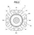
- FIG. 3 is a front view of the seal cover 30 and the seal collar 2 in FIG. 1 combined:
- FIG. 1 shows a mechanical seal device 1 as a first embodiment relative to the present invention.
- a rotary shaft 50 extending through within a bore diameter surface 60A of the apparatus main body (casing) 60.
- a seal cover;30 is mounted on an external surface 60B at the end portion of the bore diameter surface 60A of the apparatus main body 60.
- this apparatus main body 60 retains four pieces of stud bolts, not shown but where indicated by the numeral 28 in FIG. 2 , extending from the external surface 60B thereinto.
- the rotary shaft 50 mounted in the bore diameter surface is supported in freely rotatable a manner by means of bearings, not shown.
- the seal cover 30 whose abutting surface 30F is mounted onto the external surface 60B of the apparatus main body 60 has a square form as shown in FIG. 3 .
- the seal cover 30 may have a circular form as well.
- the seal cover 30 has U-shaped fixture grooves which have four equally spaced open slots opening from the center toward four corners (see FIG. 3 ).
- the fixture grooves 40 of the seal cover 30 receive stud bolts, not shown, therein and fastening nuts on the stud bolts securely holds the seal cover 30 against the external surface 60B of the apparatus main body 60.
- the seal cover 30 also disposes an inner circumferential surface 30A in a surrounding relation to the axial center.
- a positioning portion 30D is disposed at the front surface of the fixed seal cover 30 which protrudes to the outboard "A" side.
- This positioning portion 30D then forms a positioning groove 30G on outer circumference thereof.
- a fit engagement surface 30A1 forming one step surface, an annular groove defining a fluid chamber “C” and a reduction surface being formed in the inner circumference of the positioning portion 30D are disposed in a sequential manner from the inboard "L" to the outboard "A".
- the cylindrical circumferential surface in the annular groove is located between the fit engagement surface 30A1 and the reduction surface, and inner diameter thereof is arranged larger than the inner diameters of the fit engagement surface 30A1 and the reduction surface.
- Axial width dimension of the cylindrical circumferential surface in the annular groove is set large enough to contain one end portion side including the seal surface 2F of the stationary seal ring 2 and another end portion side including the opposing seal surface 12F of the rotary seal ring 12 within the fluid chamber "C".
- the reduction surface is formed in the inner circumference of the positioning portion 30D in,order to make the axial width of the annular groove large.
- the seal cover 30 disposes not only quenching passages 36A, 36B communicating from outer circumferential surface 30S thereof (see FIG. 3 ) through the fluid chamber “C” but also drain port 36B or 36C communicating from the fluid chamber “C” through the outer circumferential surface 30S.
- One of the quenching passages 36B may be utilized as a drain port. These ports for the quenching passages 36A, 36B.
- Quenching fluid (clear water or the like) coming through the piping,directly flows into the fluid chamber "C" from the quenching passages 36A, 36B and is provided to the outer circumferential side of the seal surface 2F and the opposing seal surface-12F in mutually sliding a relation to each other. Then a temperature increase due to slide frictional heat of the seal surface 2F and the opposing seal surface 12F can be lowered. At the same time, wear particles or the like caught on the seal surface 2F and the opposing seal surface- 12F and released during the sliding movement can be cleansed. And the quenching liquid (clear water or the like) circulating in the fluid chamber "C" is discharged from the drain port 36C.
- the seal cover 30 also disposes a flushing passage 35 which communicates from outer circumferential surface 30S thereof through the fit engagement surface 30A1 side in the inner circumferential surface 30A. Port of the flushing passage 35 also is provided with pipe thread to which piping, not shown, is connected. And flushing liquid (clear water) supplied intermittently from the flushing passage 35 provides a cleaning effect to the inner circumferential surfaces of the stationary seal ring (also known as first seal ring) 2 and the rotary seal ring (also known as second seal ring) 12 which are in contact with the sealed fluid, and to the inner circumferential surface 4C of the bellows 4 which is also in contact with the sealed fluid.
- first seal ring also known as first seal ring
- second seal ring also known as second seal ring
- the flushing liquid (clear water) which is supplied from the flushing passage 35 is able to provide a cleaning and cooling effect to the inner side of the inner circumferential surface 4C of the bellows 4 and also the inner side of the inner circumferential surfaces of the stationary seal ring 2 and the rotary seal ring 12.
- sealed fluid is chemical liquid, high viscosity liquid, liquid containing fine particles, fluid with varying temperature or the like which is used within the apparatus main body 60.
- the fit engagement surface 30A1 formed in the inner circumference of the seal cover 30 securely fits the secure engagement surface 6B of the case 6.
- the case 6 disposes a coupling portion 6A at one end portion which forms a flange extending radially inward.
- This coupling portion 6A is welded with a coupling surface 3B1 formed at one axial end of the ring-shaped adaptor 3B such that the entire circumference is- fully sealed.
- This adaptor 3B is welded to one end portion circumferential surface of the bellows 4 in a seal-tight relation, which forms a first mounting, portion.
- the case 6 can be formed as a portion of the first mounting portion.
- the bellows 4 is fabricated as an accordion-like annular ring by applying a reduction forming to a thin sheet metal of stainless steel, cupper alloy or the like.
- ring formed sheets can be welded at abutting inner diameter and outer diameter portions.
- resin material can be formed to an accordion like cylindrical shape.
- the cylindrical portion of the bellows 4 provides a spring means whose construction is arranged in such a way that a cross section between the inner circumferential surface 4C and the outer circumferential surface 4B has an undulated profile or a profile of inflected V-shape or Z-shape in continuity.
- This bellows 4 serves as a spring means which provides a resiliently urging force in the axial direction by means of reaction forces due to constituent elements of the bellows 4 bent in various manners.
- the other axial end portion of the bellows 4 is coupled at circumferential surface thereof with a ring-formed retainer 3A by welding or the like in a seal-tight relation, which defines a second mounting portion.
- a retainer surface 3A1 (see FIG. 2 ) formed at the end portion of the retainer 3A is coupled with the back surface of the stationary seal ring 2 in a seal-tight relation.
- a front surface of the stationary seal ring 2 defines a seal surface 2F.
- the case 6 then forms a secure engagement surface 6B on outer circumference thereof.
- This secure engagement surface 6B has a step shoulder surface which defines a lock engagement surface 6B1.
- the case 6 is- fixed to prevent movement thereof by locking this lock engagement surface 6B1 with a step shoulder surface formed in the fit engagement surface 30A1.
- a first seal groove for the O-ring providing a seal between the secure engagement surface 6B and the fit engagement surface 30A1 receives stationary O-ring (seal ring) 43 therein.
- This O-ring 43 is made of Fluoride Rubber, Nitrile Rubber, H-NBR, EPDM, Perfluoroelastomer or the like.
- a damper 5 which consists of a holding plate like a leaf spring installed in the retainer groove 6G retains the outer circumferential surface 4A of the bellows 4, which prevents the bellows 4 from swinging when the notary shaft 50 and the like exerts a rotational force or vibratory force thereto.
- a recess-like notch portion 6D in the outer circumference of the case 6 to the fluid chamber "C" side. Then a female thread is formed which reaches from the outer circumferential surface 30S of the seal cover 30 to the notch portion 6D. A set screw 27 is fastened against this female thread until an engagement portion 27A at the end tip of the set screw 27 reaches the notch portion 6D such that the case 6 does not rotate together with the rotary shaft 50.
- the entire inner circumferential surface which covers inner circumferential surface of the adaptor 3B, inner circumferential surface 4C of the bellows 4 and inner circumferential surface of the stationary seal ring 2, creates a passageway for the flushing liquid coming from the flushing passage 35 in a cavity formed- in relation to the outer circumferential surface of the rotary shaft 50. Injection of the flushing liquid prevents viscous sealed fluid-or sold matters contained in sealed fluid from getting caught on the inner circumferential surface 4C of the bellows 4, the inner circumferential surface of the stationary seal ring 2 and the inner circumferential surface of the rotary seal ring 12.
- This stationary seal ring 2 is fabricated from silicon carbide, carbon, ceramics and the like.
- the seal collar 25 disposes a second seal groove in the secure engagement circumferential surface 25C located in inner circumference thereof.
- the secure engagement circumferential surface 25C is securely attached to the outer circumferential surface of the rotary shaft 50 while the O-ring 42 provides a seal to the clearance between the engagement surfaces of both members.
- an end tip portion of the set screw 26 fastened in the seal collar 25 abuts the outer diameter surface of the rotary shaft for fixing the seal collar in relation to the rotary shaft 50.
- a coupling surface 25A is disposed on the outer circumferential surface of the protruding portion sticking out from radially inward portion of the seal collar 25 to the rotary seal ring 12 side.
- step shouldered circumferential surface in which the step is formed radially outward, being perpendicular to the coupling surface 25A of the seal collar 25. Then a drive pin 29 is press-fit into a pin bore which is disposed in the step shouldered circumferential surface of the seal collar 25.
- Front end of the rotary seal ring 12 forms an opposing seal surface 12F for sliding movement.
- This opposing seal surface 12F is not only in a seal-tight contact relation with the seal surface 2A of the stationary seal ring 2 but also is ready for sliding movement.
- Outer circumference of the rotary seal ring 12 disposes a seal-tight surface.
- the seal ring 44 for sealing between the seal tight surface and the opposing inner circumferential surface prevents quenching liquid supplied from the quenching passage 36A from leaking to the outboard "A".
- the inner circumference of the rotary seal ring 12 disposes a step shoulder surface 12C for O-ring.
- O-ring 41 is installed- in a cavity which is formed between the step shoulder surface 12C of the rotary seal ring. 12 and the coupling surface 25A of the seal collar 25.
- the clearance between the engagement surfaces of the coupling surface 25A and the step shoulder surface 12C of the rotary seal ring 12 is provided a seal thereto.
- This pin-receiving recess portion 12B receives a drive pin 29 disposed in the seal collar 25 in order to create a lock engagement between both) elements of the rotary seal ring 12 and the seal collar 25 for preventing a relative rotational movement. And the drive pin 29 transmits a rotational force of the seal collar. 25 to the rotary seal ring 12.
- This rotary seal ring 12 is fabricated from silicon carbide, carbon, ceramics and the like.
- the seal cover 30 forms a flange portion 30B which extends from the flushing passage 35 towards the inboard "L" side so as to come to a close proximity of the rotary shaft 50, which guides the flushing fluid (clean water) injected from the flushing passage 35 for flowing inside the inner circumferential surface 4C of the bellows 4 and reaching inside the inner circumferential surface of the stationary seal ring 2 and the inner circumferential surface of a portion of the rotary seal ring 12.
- the inner diameter surface of the ring formed gasket 45 should-preferably be brought in a close proximity of the rotary shaft 50.
- the reason why the gasket 45 can be brought to a close proximity of the rotary shaft 50 is- that the gasket 45 beings made of a rubber like resilient material will not cause any wear or damage even in a case of contact with each other as seen in a metal-to-metal contact.
- This gasket 45 is fabricated from rubbery resin, soft metal covered by a rubber layer and the like. Flushing liquid supplied from the flushing passage 35 is blocked and forced to change the direction by the flange portion 30B such that the liquid passes through a passage between the inner circumferential surface 4C of the bellows 4 and the rotary shaft 50 and cleans high viscosity liquid or solid matters caught on the inner circumferential surface of the rotary scarring 12 as well as on the inner circumferential surface of the stationary seal ring 2.
- Sliding surfaces of the mutually sliding seal surface 2F and opposing seal surface 12F are cleaned by means of the flushing liquid entering from radially inward with the help of a centrifugal force and are provided a lubrication effect for sliding movement of the seal surface 2F and the opposing seal surface 12F as well.
- the fluid chamber “C” in the seal cover 30 should preferably be arranged axially long enough to cover the major portion of the stationary seal ring 2 and the rotary seal ring 12.
- outer diameter surface (bottom surface of the groove) of the annular groove should be arranged in a large diameter.
- the quenching liquid supplied from the quenching passages 36A, 36B is arranged to be injected directly onto the outer circumferential side of the seal surface 2F and the opposing seal surface 12F.
- the set plate 22 is mounted to the seal collar 25 and assembled by means of bolts 23 while the protruding alignment portion 22A of the set plate 22 engages the positioning groove- 30G of the seal cover 25 for positioning.
- the seal collar 25 is then fixed with the rotary shaft 50 by fastening the socket screw 26 after the rotary seal ring 12 coupled with the seal collar 25 is aligned with respect to the stationary seal ring 2.
- the set plates 22 are mounted onto the circumference of the seal collar 25 at three equally spaced locations. The set plates 22 should be removed after the completion of assembly.
- the mechanical seal device 1 thus constructed contains the stationary seal ring 2 and the bellows 4 therewithin in which the bellows 4 installed in the inner circumferential surface 30A of the seal cover 30 exerts an urging force to the stationary seal ring 2 and provides a seal between the stationary seal ring 2 and the adapter 3B. Therefore, unlike the bore diameter surface 60A of the seal housing 60 which is a part of machinery or apparatus, the inner circumferential surface 30A of the attachable seal cover 30 is not restricted by dimensional constraints in relation to other design configurations, hence an arbitrary dimensional choice based on design calculations of the inner circumferential surface 30A in accordance with the bellows 4. As the result, performance of the bellows 4 for resiliently urging the stationary seal ring 2 will be enhanced.
- seal ability of the seal surface 2F of the stationary seal ring 2 and the opposing seal surface 12F of the rotary seal ring 12 can be improved because of their seal-tight contact. Furthermore, prevention of wear of the seal surfaces 2F, 12F under sliding movement can also be expected. And besides, the construction is simplified as the bellows 4 and the stationary seal ring 2 are contained within the seal cover 30 and no conventional sleeve is needed for installing seal rings. Fabrication cost can also be reduced at the same time.
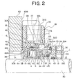
- FIG. 2 is a cross sectional view of a half portion of a mechanical seal device 1 as a second embodiment related to the present invention.
- a guide separation annulus 21 in a cylindrical form is coupled with the inner diameter portion- of the flange portion 30B extending radially inward from the seal cover 30.
- the outer circumferential surface of the guide separation annulus 21 is arranged so as to form a fluid passage way in conjunction with the inner circumferential surface of the adaptor 3B, the inner circumferential surface 4C of the bellows 4 and the inner circumferential surface of the retainer 3A.
- This fluid passageway communicates the flushing passage 35 via a passageway formed between the flange portion 30B and the adaptor 3B.
- flushing liquid injected from the flushing passage 35 not only cleans the inner circumferential surface 4C of the bellows 4 but also cleans the inner circumferential side of the seal surface 2F and the opposing seal surface 12F. Also it can effectively prevent high viscosity fluid from sticking between the seal surface 2F and the opposing seal surface 12F. As the result, seal performance of the relatively sliding seal surfaces 2F, 12F can be enhanced.
- FIG. 2 Front view of FIG. 2 is the same as that in FIG. 3 .
- the foresaid mechanical seal device 1 explains an example in which a stationary seal ring. 2 is attached to a bellows 4.
- the first mounting portion at one end of the bellows 4 is attached to the seal collar 25 while the second mounting portion is attached to the rotary seal ring 12, instead.
- the stationary seal ring 2 is securely fitted to the inner circumferential surface 6C of the case 6. Then the seal surface 2F of the stationary seal ring 2 and the opposing seal surface 12F of the rotary seal ring 12 are brought to a seal-tight contact to each other.
- Other configurations are more or less the same as those in FIG. 1 .
- Advantages of the mechanical seal device 1 are the same as those mentioned for FIG. 1 .
- a seal cover retains a flange portion at seal housing side thereof which extends radially inward in a surrounding relation relative to the rotary shaft and retains a flushing passage which communicates a passageway passing between the flange portion and the first mounting portion and passing within the inner circumferential surface of the bellows.
- a seal cover retains a flange portion at seal housing side thereof which extends radially inward in a surrounding relation relative to the rotary shaft and also retains a flushing passage which communicates a passageway passing between the flange portion and the first mounting portion and passing within the inner circumferential surface of the bellows, when flushing liquid is injected from the flushing passage the sealed fluid is blocked by the flange portion and the flushing fluid prevents the sealed fluid-from breaking into the seal ring side, and is able to securely clean the surfaces of the bellows, stationary seal ring and rotary seal ring which are important surfaces from the operation point of view.
- troubles with bellows due to chemical liquid, high viscosity liquid, liquid containing impurities and the like can be prevented while wear of the seal surfaces due to impurities caught between the opposing seal surfaces can also be prevented in an effective manner.
- a guide separation annulus is disposed at the inner circumferential end portion of the flange portion which forms a passageway in conjunction with the inner circumferential surface of the bellows.
- the flushing liquid prevents chemical liquid, liquid containing slurry and the like from breaking into the inner circumferential surface of the bellows and is able to provide an intensive cleaning effect to the inner circumferential surface of the bellows.
- the flushing liquid is injected onto the inner circumferential surfaces of the stationary seal ring and the rotary seal ring for a cleaning effect and also is able to provide a strong cooling effect against slide friction heat of the seal surfaces.
- the first mounting portion retains a case which is coupled with the inner circumferential surface of the seal cover in freely detachable a manner and is locked in a rotational direction.
- the mechanical seal device of the third or fourth invention as the first mounting portion retains a case which is coupled with the inner circumferential surface of the seal cover in freely detachable a manner and is locked in a rotational direction, it becomes straightforward to assemble and disassemble the bellows or the stationary seal ring. Even in case of some trouble with O-ring between the case and the seal cover caused by chemical liquid, it is advantageous that replacement of the O-ring is straightforward
- a mechanical seal device of the present invention is advantageous in that the mechanical seal device is always able to urge at a prescribed pressure regardless of sealed fluid with high viscosity or containing impurities.
- the mechanical seal device is also advantageous in that the seal cover is able to contain a multitude of functions therewithin.
- the mechanical seal device is further advantageous in that the seal cover contains the entirety therewithin and maintenance thereof is easy while installation thereof is simple.
Landscapes
- Engineering & Computer Science (AREA)
- General Engineering & Computer Science (AREA)
- Mechanical Engineering (AREA)
- Mechanical Sealing (AREA)
Applications Claiming Priority (2)
| Application Number | Priority Date | Filing Date | Title |
|---|---|---|---|
| JP2005179599 | 2005-06-20 | ||
| PCT/JP2006/311924 WO2006137305A1 (fr) | 2005-06-20 | 2006-06-14 | Joint mécanique |
Publications (3)
| Publication Number | Publication Date |
|---|---|
| EP1895209A1 true EP1895209A1 (fr) | 2008-03-05 |
| EP1895209A4 EP1895209A4 (fr) | 2011-10-05 |
| EP1895209B1 EP1895209B1 (fr) | 2012-12-26 |
Family
ID=37570335
Family Applications (1)
| Application Number | Title | Priority Date | Filing Date |
|---|---|---|---|
| EP06766693A Ceased EP1895209B1 (fr) | 2005-06-20 | 2006-06-14 | Joint mécanique |
Country Status (5)
| Country | Link |
|---|---|
| US (1) | US8231130B2 (fr) |
| EP (1) | EP1895209B1 (fr) |
| JP (1) | JP5087396B2 (fr) |
| CN (1) | CN101198811B (fr) |
| WO (1) | WO2006137305A1 (fr) |
Cited By (2)
| Publication number | Priority date | Publication date | Assignee | Title |
|---|---|---|---|---|
| EP2146120A4 (fr) * | 2007-04-12 | 2011-11-16 | Eagle Ind Co Ltd | Dispositif d'étanchéité mécanique |
| US8857819B2 (en) | 2011-09-12 | 2014-10-14 | Eagle Industry Co., Ltd. | Mechanical seal |
Families Citing this family (13)
| Publication number | Priority date | Publication date | Assignee | Title |
|---|---|---|---|---|
| GB0805864D0 (en) * | 2008-04-01 | 2008-04-30 | Crane John Uk Ltd | Internally pressurised seals |
| JP4864995B2 (ja) * | 2009-03-06 | 2012-02-01 | 日本ピラー工業株式会社 | メカニカルシール |
| US8517388B2 (en) * | 2009-03-31 | 2013-08-27 | Eagle Industry Co., Ltd. | Bellows type mechanical seal |
| WO2010123025A1 (fr) | 2009-04-23 | 2010-10-28 | イーグル工業株式会社 | Dispositif d'étanchéité mécanique |
| CN104395655B (zh) * | 2012-08-29 | 2018-02-02 | 伊格尔工业股份有限公司 | 机械密封 |
| EP2896854B1 (fr) * | 2012-09-11 | 2016-11-09 | Eagle Industry Co., Ltd. | Garniture mécanique d'étanchéité |
| WO2014142265A1 (fr) * | 2013-03-14 | 2014-09-18 | イーグルブルグマンジャパン株式会社 | Dispositif de joint mécanique |
| CN103148011B (zh) * | 2013-03-25 | 2015-07-22 | 宁波伏尔肯机械密封件制造有限公司 | 一种卫生泵用机械密封装置 |
| JP6509896B2 (ja) * | 2014-11-04 | 2019-05-08 | イーグル工業株式会社 | メカニカルシール装置 |
| CN109073090B (zh) * | 2016-04-27 | 2020-10-30 | 伊格尔工业股份有限公司 | 机械密封件 |
| CN106122484B (zh) * | 2016-08-18 | 2017-12-05 | 浙江工业大学 | 用于动静压型干气密封的内置密封介质节流调控装置 |
| US11536370B2 (en) * | 2019-11-27 | 2022-12-27 | Eaton Intelligent Power Limited | Bellows seal assembly |
| WO2025034673A2 (fr) * | 2023-08-04 | 2025-02-13 | A.W. Chesterton Company | Système de régulation de rinçage actif destiné à être utilisé avec un joint mécanique ou un ensemble garniture |
Family Cites Families (25)
| Publication number | Priority date | Publication date | Assignee | Title |
|---|---|---|---|---|
| CH141626A (de) * | 1929-10-07 | 1930-08-15 | Sulzer Ag | Stopfbüchse. |
| US2432694A (en) * | 1944-11-09 | 1947-12-16 | Crane Packing Co | Fluid seal |
| US2474123A (en) * | 1946-08-12 | 1949-06-21 | Crane Packing Co | Retainer for fluid seals |
| US3051497A (en) * | 1957-01-25 | 1962-08-28 | Rolls Royce | Sealing means between relatively rotating parts |
| US3091469A (en) * | 1959-03-04 | 1963-05-28 | Thompson Ramo Wooldridge Inc | Seal |
| US3515394A (en) * | 1964-06-05 | 1970-06-02 | Sealol | Vibration damping means for resilient convoluted members |
| US3391942A (en) * | 1965-09-17 | 1968-07-09 | Sealol | Rotary mechanical fluid seal |
| US3397894A (en) * | 1968-01-02 | 1968-08-20 | Chandler Evans Inc | Rotary shaft seal |
| US3526408A (en) * | 1969-01-02 | 1970-09-01 | Borg Warner | Mechanical seal construction |
| US4175753A (en) * | 1977-09-29 | 1979-11-27 | Borg-Warner Corporation | Mechanical seal |
| US4136887A (en) * | 1977-10-04 | 1979-01-30 | Borg-Warner Corporation | Bellows type mechanical seal |
| US4335888A (en) * | 1978-03-20 | 1982-06-22 | Nippon Pillar Packing Co. Ltd. | Mechanical seal |
| US4453722A (en) * | 1982-12-20 | 1984-06-12 | United Technologies Corporation | Seal means |
| FR2589955B1 (fr) * | 1985-11-08 | 1989-12-08 | Sealol | Dispositif d'etancheite de turbopompe |
| JPH0398375A (ja) | 1989-09-11 | 1991-04-23 | Minolta Camera Co Ltd | 画像読取装置 |
| JPH0632527Y2 (ja) | 1990-01-29 | 1994-08-24 | イーグル工業株式会社 | メカニカルシール |
| JPH07109253B2 (ja) | 1990-10-11 | 1995-11-22 | 日本ピラー工業株式会社 | 軸封装置 |
| US5823539A (en) * | 1995-04-21 | 1998-10-20 | Environamics Corporation | Environmentally safe pump having a bellows seal and a split ring shaft seal |
| US5873574A (en) * | 1996-07-18 | 1999-02-23 | John Crane Sealol Inc. | Bellows seal with reverse pressure capability |
| US5954341A (en) * | 1996-07-30 | 1999-09-21 | John Crane Sealol Inc. | Bellows seal with drive collar for reverse pressure capability |
| US5924697A (en) * | 1997-03-03 | 1999-07-20 | Durametallic Corporation | Double gas seal with bellows supported by backing and support rings |
| JP3072094B1 (ja) | 1999-06-15 | 2000-07-31 | 日本ピラー工業株式会社 | メカニカルシ―ル |
| JP3762636B2 (ja) | 2000-11-21 | 2006-04-05 | イーグル工業株式会社 | メカニカルシール |
| JP4111698B2 (ja) * | 2001-08-31 | 2008-07-02 | イーグル工業株式会社 | メカニカルシール装置 |
| JP2003074714A (ja) | 2001-08-31 | 2003-03-12 | Eagle Ind Co Ltd | メカニカルシール装置 |
-
2006
- 2006-06-14 CN CN2006800218255A patent/CN101198811B/zh not_active Expired - Fee Related
- 2006-06-14 US US11/922,571 patent/US8231130B2/en not_active Expired - Fee Related
- 2006-06-14 JP JP2007522250A patent/JP5087396B2/ja not_active Expired - Fee Related
- 2006-06-14 WO PCT/JP2006/311924 patent/WO2006137305A1/fr not_active Ceased
- 2006-06-14 EP EP06766693A patent/EP1895209B1/fr not_active Ceased
Cited By (2)
| Publication number | Priority date | Publication date | Assignee | Title |
|---|---|---|---|---|
| EP2146120A4 (fr) * | 2007-04-12 | 2011-11-16 | Eagle Ind Co Ltd | Dispositif d'étanchéité mécanique |
| US8857819B2 (en) | 2011-09-12 | 2014-10-14 | Eagle Industry Co., Ltd. | Mechanical seal |
Also Published As
| Publication number | Publication date |
|---|---|
| US20090085300A1 (en) | 2009-04-02 |
| CN101198811B (zh) | 2012-08-22 |
| WO2006137305A1 (fr) | 2006-12-28 |
| EP1895209A4 (fr) | 2011-10-05 |
| JPWO2006137305A1 (ja) | 2009-01-15 |
| US8231130B2 (en) | 2012-07-31 |
| EP1895209B1 (fr) | 2012-12-26 |
| JP5087396B2 (ja) | 2012-12-05 |
| CN101198811A (zh) | 2008-06-11 |
Similar Documents
| Publication | Publication Date | Title |
|---|---|---|
| EP1788290B1 (fr) | Dispositif de joint mécanique | |
| EP1895209B1 (fr) | Joint mécanique | |
| US5863047A (en) | Mechanical seal assembly | |
| EP1288541B1 (fr) | Garniture mécanique d'étanchéité | |
| JP5615267B2 (ja) | メカニカルシール装置 | |
| EP1288542B1 (fr) | Garniture mécanique d'étanchéité | |
| JP5271260B2 (ja) | メカニカルシール装置 | |
| US8201830B2 (en) | Airtight magnetic seal for bearing casings | |
| EP2295835B1 (fr) | Dispositif de joint mécanique | |
| CN102939485B (zh) | 球阀密封组件以及包含该球阀密封组件的球阀 | |
| AU2016385377B2 (en) | Slurry seal assembly | |
| US12510161B2 (en) | Mechanical sealing device for sealing liquid | |
| JP5124784B2 (ja) | メカニカルシール装置 | |
| JP3782690B2 (ja) | メカニカルシール装置 | |
| EP1203885B1 (fr) | Pompe à engrenages | |
| KR101837626B1 (ko) | 간결한 이중 씰링면 구조를 갖는 분할형 메카니컬 씰 | |
| CA2845143C (fr) | Ensemble joint carbone | |
| JP4391205B2 (ja) | メカニカルシール装置 |
Legal Events
| Date | Code | Title | Description |
|---|---|---|---|
| PUAI | Public reference made under article 153(3) epc to a published international application that has entered the european phase |
Free format text: ORIGINAL CODE: 0009012 |
|
| 17P | Request for examination filed |
Effective date: 20071213 |
|
| AK | Designated contracting states |
Kind code of ref document: A1 Designated state(s): DE |
|
| DAX | Request for extension of the european patent (deleted) | ||
| RBV | Designated contracting states (corrected) |
Designated state(s): DE |
|
| DAX | Request for extension of the european patent (deleted) | ||
| A4 | Supplementary search report drawn up and despatched |
Effective date: 20110905 |
|
| RIC1 | Information provided on ipc code assigned before grant |
Ipc: F16J 15/36 20060101ALI20110830BHEP Ipc: F16J 15/34 20060101AFI20110830BHEP |
|
| GRAP | Despatch of communication of intention to grant a patent |
Free format text: ORIGINAL CODE: EPIDOSNIGR1 |
|
| GRAS | Grant fee paid |
Free format text: ORIGINAL CODE: EPIDOSNIGR3 |
|
| GRAA | (expected) grant |
Free format text: ORIGINAL CODE: 0009210 |
|
| AK | Designated contracting states |
Kind code of ref document: B1 Designated state(s): DE |
|
| REG | Reference to a national code |
Ref country code: DE Ref legal event code: R096 Ref document number: 602006033854 Country of ref document: DE Effective date: 20130228 |
|
| PLBE | No opposition filed within time limit |
Free format text: ORIGINAL CODE: 0009261 |
|
| STAA | Information on the status of an ep patent application or granted ep patent |
Free format text: STATUS: NO OPPOSITION FILED WITHIN TIME LIMIT |
|
| 26N | No opposition filed |
Effective date: 20130927 |
|
| REG | Reference to a national code |
Ref country code: DE Ref legal event code: R097 Ref document number: 602006033854 Country of ref document: DE Effective date: 20130927 |
|
| PGFP | Annual fee paid to national office [announced via postgrant information from national office to epo] |
Ref country code: DE Payment date: 20170606 Year of fee payment: 12 |
|
| REG | Reference to a national code |
Ref country code: DE Ref legal event code: R119 Ref document number: 602006033854 Country of ref document: DE |
|
| PG25 | Lapsed in a contracting state [announced via postgrant information from national office to epo] |
Ref country code: DE Free format text: LAPSE BECAUSE OF NON-PAYMENT OF DUE FEES Effective date: 20190101 |