EP1897737B1 - Déflecteur d'air - Google Patents
Déflecteur d'air Download PDFInfo
- Publication number
- EP1897737B1 EP1897737B1 EP07017438A EP07017438A EP1897737B1 EP 1897737 B1 EP1897737 B1 EP 1897737B1 EP 07017438 A EP07017438 A EP 07017438A EP 07017438 A EP07017438 A EP 07017438A EP 1897737 B1 EP1897737 B1 EP 1897737B1
- Authority
- EP
- European Patent Office
- Prior art keywords
- windbreak
- wind deflector
- control unit
- transmission
- control means
- Prior art date
- Legal status (The legal status is an assumption and is not a legal conclusion. Google has not performed a legal analysis and makes no representation as to the accuracy of the status listed.)
- Not-in-force
Links
- 230000005540 biological transmission Effects 0.000 claims description 57
- 230000008054 signal transmission Effects 0.000 claims description 7
- 230000001939 inductive effect Effects 0.000 claims description 4
- 230000003287 optical effect Effects 0.000 claims description 3
- 230000003993 interaction Effects 0.000 description 6
- ORQBXQOJMQIAOY-UHFFFAOYSA-N nobelium Chemical compound [No] ORQBXQOJMQIAOY-UHFFFAOYSA-N 0.000 description 6
- 238000001514 detection method Methods 0.000 description 3
- 238000004891 communication Methods 0.000 description 1
- 230000008878 coupling Effects 0.000 description 1
- 238000010168 coupling process Methods 0.000 description 1
- 238000005859 coupling reaction Methods 0.000 description 1
- 230000005674 electromagnetic induction Effects 0.000 description 1
- 230000002349 favourable effect Effects 0.000 description 1
- 230000006698 induction Effects 0.000 description 1
- 238000003780 insertion Methods 0.000 description 1
- 230000037431 insertion Effects 0.000 description 1
- HZRSNVGNWUDEFX-UHFFFAOYSA-N pyraclostrobin Chemical compound COC(=O)N(OC)C1=CC=CC=C1COC1=NN(C=2C=CC(Cl)=CC=2)C=C1 HZRSNVGNWUDEFX-UHFFFAOYSA-N 0.000 description 1
- 238000000926 separation method Methods 0.000 description 1
Images




Classifications
-
- B—PERFORMING OPERATIONS; TRANSPORTING
- B60—VEHICLES IN GENERAL
- B60J—WINDOWS, WINDSCREENS, NON-FIXED ROOFS, DOORS, OR SIMILAR DEVICES FOR VEHICLES; REMOVABLE EXTERNAL PROTECTIVE COVERINGS SPECIALLY ADAPTED FOR VEHICLES
- B60J7/00—Non-fixed roofs; Roofs with movable panels, e.g. rotary sunroofs
- B60J7/22—Wind deflectors for open roofs
- B60J7/223—Wind deflectors for open roofs specially adapted for convertible cars
Definitions
- the invention relates to a Windstop adopted for motor vehicles, especially for convertible vehicles, comprising a vehicle fixed windstop base on which a wind deflector extending in a wind deflector between an operative position and an inoperative position is movably mounted, and a drive means for moving the wind deflector between the ineffective and the effective position and vice versa.
- Windstop interestsen are for example from the DE 296 15 342 U1 or the DE 43 38 102 A1 or the EP 0 361 624 A1 or the EP 1 621 386 A2 known.
- the invention is therefore based on the object to improve a Windstop worn of the generic type such that an operation of the same is possible optimally.
- the drive means energy from an electrical system of the motor vehicle by means of an energy transfer device can be supplied and that the energy transfer device a first, arranged on the Windstopbasis element and a second, on a side wall of the body
- Motor vehicle arranged element comprises, which is mounted on the motor vehicle in functional position WindstopANT Transferring energy from the electrical system of the motor vehicle to the arranged on the Windstopbasis drive device, and that the first element and the second element are integrated in a fixing device for fixing the Windstopbasis to the body.
- the advantage of the solution according to the invention is the fact that the energy transfer device according to the invention is then always able to transfer energy when the wind stop device is mounted on the motor vehicle in functional position, since in the functional position of the wind stop device inevitably the first element of the energy transfer device and the second element of the energy transmission device are positioned so that they are able to transfer energy from the electrical system of the body to the Windstopbasis, wherein the Windstop nails can be mechanically fixed simultaneously by connecting the Windstopbasis with the body of the vehicle and thus in this case Energy transfer device according to the invention in a simple manner and visually completely inconspicuous realizable.
- the first element of the energy transmission device and the second element of the energy transmission device as separate elements, which are arranged on the one hand on the bodywork and on the other hand on the windstop base.
- the first element is arranged integrated in the wind stop base, since then an optical design of the wind stop base is possible, in which the presence of the first element of the energy transmission device is completely inconspicuous.
- the second element is arranged integrally in a side wall of the body, since thus also the second element of the energy transmission device can be arranged inconspicuously and optimally optimized in the bodywork of the motor vehicle.
- the second element is integrated in an inner lining of the side wall of the body.
- a first exemplary embodiment provides that the first and the second element of the energy transmission device transmit electrical energy via contacting electrical contact surfaces.
- first and the second element are designed as plug contact elements, that is, when one of the elements forms a plug and the other of the elements a plug receptacle.
- another advantageous exemplary embodiment provides that the first and the second element of the energy transmission device transmit electrical energy without contact.
- Such a contactless transmission of electrical energy takes place in the simplest case via electromagnetic induction.
- the drive means is associated with a control unit which controls the drive means for moving the wind deflector between the inoperative and the active position and vice versa that the control unit with a
- a signal transmission unit is provided, which comprises a first, arranged on the Windstopbasis transmission element and a second, arranged on a side wall of the body transmission element, and the transmission elements are integrated in a fixing device for fixing the Windstopbasis to the body.
- Provision of such a control unit has the advantage that control intelligence can thus be transferred to the wind stop device and thus, for example, in the wind stop base it is already possible to interrogate positions of the wind block relative to the wind stop base, that is, for example, tilting of the wind block relative to the wind stop base, and consequently according to the existing tilting positions, a further control of movements of the wind deflector can take place.
- the ease of communication with the on-board function control improves ease of use.
- Control functions of the convertible vehicle which detect and / or display and / or control individual functions of the motor vehicle, are to be understood here as an on-vehicle function control.
- on-vehicle function control includes a control unit for on-dash display control, a dashboard function key detection unit, a window position detection and control unit, and / or a roof control unit.
- control unit could for example be designed so that this own, provided for example on the Windstop worn or interacting with the control unit portable, controls, so that by pressing these controls the individual functions of the wind deflector, in particular moving the wind deflector between the effective Position and the inoperative position, are controllable.
- These transmission elements can in principle be provided as separate transmission elements.
- the first transmission element is integrated in the wind stop base.
- a design of the body of the motor vehicle can also be optimized if the second transmission element is integrated into the side wall of the body, in particular if the second transmission element is integrated in an inner lining of the side wall of the body.
- the transmission elements are formed as plug-in contact elements, so that one of them is integrated as a plug and the other as a plug receptacle.
- Such a contactless interaction can be realized for example by the fact that the transmission elements interact inductively with each other.
- An alternative to an inductive interaction provides that the transmission elements optically interact with each other.
- a further solution according to the invention provides that the control unit communicates with a portable manual control.
- the manual control and the control unit could be connected by a line. However, it is particularly advantageous if the manual control and the control unit communicate with each other without contact.
- control unit communicates with the manual control via the vehicle-side function control, wherein the vehicle-side function control can be embodied, for example, as a function control unit for a vehicle lock.
- an advantageous solution provides that the function control via the control unit causes the wind deflector to move from the inoperative position to the active position when the motor vehicle exceeds a predeterminable speed.
- a further embodiment provides that the function control via the control unit causes a movement of the wind deflector from the active to the inoperative position when a reverse gear is engaged.
- an embodiment provides, as an alternative or in addition to the previous functions, that the function control via the control unit causes a movement of the wind deflector from the inoperative position to the operative position when all the windows of the motor vehicle are started up.
- an embodiment provides as an alternative or in addition to the previous solutions, that the function control via the control unit causes a movement of the wind deflector between an inoperative position and an operative position or vice versa, when a corresponding control button on the vehicle is operated.
- the aforementioned functional modes of the function control can be fixed.
- the aforementioned object is achieved not only by a Windstop tilt of the type described above according to the individual embodiments, but also by a convertible vehicle, which is provided with one or more embodiments of Windstop raised described above.
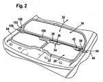
- a first exemplary embodiment of a wind stop device 10 according to the invention mounted on a body 14 of a convertible vehicle 12, behind a front row of seats 18, comprises a wind stop base 20 which serves as cover 22 for an open area 24 of the body 14 lying behind the front seat row 18.
- a wind deflector indicated generally at 30 is supported which is relative to the windstop base 20 between an effective position extending transversely to a belt line 16 of the body and an ineffective position extending approximately parallel to the belt line 16, as indicated by the arrow 32 , is movable ( Fig. 1 ).
- the wind stop base 20 is provided with a drive device designated as a whole by 34, which preferably comprises a drive motor, in particular an electric motor 36 and a transmission 38, with which the wind deflector 30 for performing a pivoting movement about an axis 40th is drivable ( Fig. 2 ).
- a drive device designated as a whole by 34 which preferably comprises a drive motor, in particular an electric motor 36 and a transmission 38, with which the wind deflector 30 for performing a pivoting movement about an axis 40th is drivable ( Fig. 2 ).
- the drive device 34 is still associated with a control unit 42, which on the one hand detects a pivot position of the wind deflector 30 and on the other hand, according to a control unit 42 predetermined position of the wind deflector 30 controls the drive means 34.
- an energy transfer device 50 is provided, which is arranged on the Windstopbasis 20 first element 52 and at the Body 14 arranged second element 54 which allow in the first embodiment, a power supply by contacting electrical contacts.
- the first element 52 is designed as a plug 60 extending in a plug-in direction 56, which has two contact surfaces 62 and 64 which follow one another in the plug-in direction and which are formed, for example, by lateral surfaces of the plug 60 and are electrically insulated from one another ( Fig. 3 ).
- the plug 60 can be inserted in the plug-in direction 56 into a plug receptacle 70, which has two contact clips 72, 74 in an inner space 76 which, when the plug 60 is plugged into the inner space 76, make contact with the contact surfaces 62 and 64, respectively.
- the second element 54 forming plug receptacle 70 is connected with their contact bars 72, 74 to the electrical system 44 of the body 14 and thus able to supply the arranged in the Windstopbasis 20 drive means 34 and the control unit 42 with energy.
- the Windstopbasis 20 at the height of the belt line 16 of the body 14 is disposed between side walls 82 and 84 of the body, for example, the second elements 54 performing plug receptacle 70 is disposed in the side wall 82, so that the interior 76 via an opening 86 is accessible, which is in the region of a passenger compartment of the body 14 facing inner lining 88 of the side wall 82, so that through this opening 86 of the plug 60 in the connector receptacle 70, which is integrated as a whole in the side wall 82, can be inserted.
- the plug 60 simultaneously forms a fixing bolt for mechanically fixing the Windstopbasis 20 relative to the body 14, in particular the side wall 82 thereof, and the plug receptacle 70 forms a mechanically correspondingly stable Fixierfact for the fixing bolt.
- a function control 90 for conventional vehicle functions which may also be formed by a plurality of function control units for example, as in Fig. 2 illustrated, on the opposite side of the power transmission unit 50 Windstop dressed 10, a signal transmission unit 100 is provided which also works in the simplest case with touching electrical contacts.
- the signal transmission unit 100 comprises a first transmission element 102 provided on the wind stop base 20 and a second transmission element 104 integrated in the side wall 84, which represent a separation point from a control line 106 guided from the function control 90 to the control unit 42.
- the first transmission element 102 and the second transmission element 104 are also formed as a plug or plug receptacle and also integrated into a fixing or a Fixierfact for mechanically fixing the Windstopbasis 20 to the body 14 between the side walls 82 and 84, so that on the fixation the wind stop base 20 on the side wall 84 at the same time the control line 106 between the control unit 42 and the function control 90 can be closed by contacting contacts.
- the first transmission element 102 according to the plug 60 and the second transmission element 104 is formed and executed according to the connector receptacle 70, however, in this case, the plug 60 is movable relative to the Windstopbasis 20 in the direction of insertion 56, while the plug 60th the power transmission device is fixedly connected to the wind stop base 20.
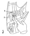
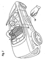
- control unit 42 wirelessly communicates with a portable handset 120, so that by the manual operation 120 is also possible to move the wind deflector 30 between the operative position and the inoperative position back and forth.
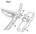
- FIG Fig. 8 In a second embodiment of a wind stop device according to the invention, shown in FIG Fig. 8 , those parts which are identical to those of the first embodiment are given the same reference numerals, so that with respect to the description thereof, reference is made to the explanations of the first embodiment in its entirety.
- the energy transfer device 50 ' is designed as a non-contact energy transfer device, wherein the first element 52', arranged on the Windstopbasis 20, and the second element 54 ', integrated into the side wall 82, cooperate without contact.
- an inductive coupling takes place between the second element 54 'and the first element 52', and thus an induction of energy is transferred from the on-board network 44 of the convertible vehicle 12 to the windstop base 20.
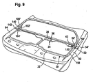
- the fixation of the Windstopbasis 20 takes place in a conventional manner via a mechanical plug pin 130 which is inserted into a socket pin receptacle 132, wherein preferably the elements 52 'and 54' can be arranged coaxially to the socket pin 130.
- the wind stop device is additionally ( Fig. 9 ) on the opposite side of the Windstopbasis 20 also via a locking pin 140 which is inserted into a socket pin receptacle 142, fixed to the body 14, wherein the two locking pin receptacles 132 and 142 are integrated into the respective side walls 82 and 84, respectively.
- the second element 54 is integrated into the side wall 82, preferably so that it is arranged on one of the windstop base 20 facing side of the side wall 82, preferably in the region of the inner lining 88.
- the first transmission element 102 'and the second transmission element 104' of the signal transmission unit 100 ' are provided in the region of the plug pin 140 and the socket pin receptacle 142, which preferably also contact one another without contact interact.
- the second embodiment works in the same way as the first embodiment, so that with regard to the description of the individual functions and the interaction, in particular with the function control 90, the statements on the first embodiment can be made in full.
- the power transmission device 50 'with the first element 52' and the second element 54 'coaxial with the socket pins 130 it is not absolutely necessary to arrange the power transmission device 50 'with the first element 52' and the second element 54 'coaxial with the socket pins 130. It is equally possible, the energy transfer device 50 'with the first Element 52 'and the second member 54' eccentrically to the socket pin 130, for example, at any point of a cover 150 of the cover 22 to arrange, in so far as it is parallel to an element of the body 14, for example, one of the side walls 82, 84 extends.
- the signal transmission unit 100 'with the first transmission element 102' can be arranged anywhere on the cover frame 150 insofar as it runs parallel to an element of the body 14, for example one of the side walls 82, 84, in which case the corresponding one second transmission element 104 is disposed in the respective area of the body adjacent to the cover frame 150, for example the side walls 82, 84.
Landscapes
- Engineering & Computer Science (AREA)
- Mechanical Engineering (AREA)
- Power-Operated Mechanisms For Wings (AREA)
- Specific Sealing Or Ventilating Devices For Doors And Windows (AREA)
- Air-Conditioning For Vehicles (AREA)
- Electric Propulsion And Braking For Vehicles (AREA)
- Current-Collector Devices For Electrically Propelled Vehicles (AREA)
Claims (24)
- Déflecteur d'air pour véhicules automobiles (12), en particulier pour véhicules cabriolets, comprenant une base de déflecteur (20) pouvant être montée de façon solidaire du véhicule, sur laquelle un déflecteur (30) s'étendant dans une surface de déflecteur est monté de façon à pouvoir se déplacer entre une position active et une position inactive, et un dispositif d'entraînement (34) pour le déplacement du déflecteur (30) entre la position inactive et la position active et inversement, de l'énergie provenant d'un réseau de bord (44) du véhicule (12) pouvant être amenée au dispositif d'entraînement (34) au moyen d'un dispositif de transmission d'énergie (50), caractérisé en ce que le dispositif de transmission d'énergie (50) comprend un premier élément (52) disposé sur la base du déflecteur (20) et un second élément (54) disposé sur une paroi latérale (82, 84) de la carrosserie (14) du véhicule (12), le premier élément et le second élément transmettant de l'énergie provenant du réseau de bord (44) du véhicule (12) au dispositif d'entraînement (34) disposé sur la base du déflecteur (20) quand le déflecteur (10) est monté en position de fonctionnement sur le véhicule (12), et en ce que le premier élément (52) et le second élément (54) sont intégrés dans un système de fixation (60, 70) pour la fixation de la base de déflecteur (20) sur la carrosserie (14).
- Déflecteur selon la revendication 1, caractérisé en ce que le premier élément (52) est disposé de façon intégrée dans la base de déflecteur (20).
- Déflecteur selon la revendication 1 ou 2, caractérisé en ce que le second élément (54) est disposé de façon intégrée dans une paroi latérale (82, 84) de la carrosserie (14).
- Déflecteur selon l'une quelconque des revendications précédentes, caractérisé en ce que le premier et le second éléments (52, 54) du dispositif de transmission d'énergie (50) transmettent de l'énergie électrique au moyen de surfaces de contact (62, 64, 72, 74) électriques qui se touchent.
- Déflecteur selon la revendication 4, caractérisé en ce que le premier et le second éléments (52, 54) sont conçus sous forme d'éléments de contact à fiches (60, 70).
- Déflecteur selon l'une quelconque des revendications 1 à 3, caractérisé en ce que le premier et le second éléments (52', 54') transmettent de l'énergie électrique sans contact au dispositif de transmission d'énergie (50') .
- Déflecteur pour véhicules (12), en particulier pour véhicules cabriolets, comprenant une base de déflecteur (20) pouvant être montée de façon solidaire du véhicule, sur laquelle un déflecteur (30) s'étendant dans une surface du déflecteur est monté de façon à pouvoir se déplacer entre une position active et une position inactive, et un dispositif d'entraînement (34) pour le déplacement du déflecteur (30) entre la position inactive et la position active et inversement, une unité de commande (42) étant attribuée au dispositif d'entraînement (34), laquelle unité actionne le dispositif d'entraînement (34) pour le déplacement du déflecteur (30) entre la position inactive et la position active et inversement, l'unité de commande (42) communiquant avec une commande de fonction (90) côté véhicule, une unité de transmission de signal (100) étant prévue, caractérisé en ce que l'unité de transmission de signal (92) comprend un premier élément de transmission (102) disposé sur la base de déflecteur (20) et un second élément de transmission (104) disposé sur une paroi latérale (82, 84) de la carrosserie (14) et en ce que le premier élément de transmission (102) et le second élément de transmission (104) sont intégrés dans un système de fixation (60, 70) pour la fixation de la base de déflecteur (20) sur la carrosserie (14).
- Déflecteur selon la revendication 7, caractérisé en ce que le premier élément de transmission (102) est intégré dans la base de déflecteur (20).
- Déflecteur selon la revendication 7 ou 8, caractérisé en ce que le second élément (104) est intégré dans la paroi latérale (82, 84) de la carrosserie (14).
- Déflecteur selon l'une quelconque des revendications 7 à 9, caractérisé en ce que les éléments de transmission (102, 104) interagissent les uns avec les autres au moyen de surfaces de contact électriques qui se touchent.
- Déflecteur selon l'une quelconque des revendications 7 à 9, caractérisé en ce que les éléments de transmission (102, 104) interagissent les uns avec les autres sans contact.
- Déflecteur selon la revendication 11, caractérisé en ce que les éléments de transmission (102, 104) interagissent les uns avec les autres de façon inductive.
- Déflecteur selon la revendication 12, caractérisé en ce que les éléments de transmission (102, 104) interagissent les uns avec les autres au plan optique.
- Déflecteur selon l'une quelconque des revendications 7 à 13, caractérisé en ce que l'unité de commande (42) communique avec une commande manuelle (120) portative.
- Déflecteur selon la revendication 14, caractérisé en ce que la commande manuelle (120) et l'unité de commande (42) communiquent sans contact.
- Déflecteur selon la revendication 14, caractérisé en ce que l'unité de commande (42) communique avec la commande manuelle (120) au moyen de la commande de fonction (90) côté véhicule.
- Déflecteur selon la des revendication 16, caractérisé en ce que la commande de fonction (90) communique sans contact avec la commande manuelle (120) portative.
- Déflecteur selon l'une quelconque des revendications 7 à 17, caractérisé en ce que la commande de fonction (90) ordonne par l'unité de commande (42) un déplacement du déflecteur (30) de la position inactive à la position active lorsque le véhicule (12) dépasse une vitesse prédéfinissable.
- Déflecteur selon l'une quelconque des revendications 7 à 18, caractérisé en ce que la commande de fonction (90) ordonne par l'unité de commande (42) un déplacement du déflecteur (30) de la position inactive à la position active lorsqu'une capote (116) du véhicule (12) est ouverte.
- Déflecteur selon l'une quelconque des revendications 7 à 19, caractérisé en ce que la commande de fonction (90) ordonne par l'unité de commande (42) un déplacement du déflecteur (30) de la position active à la position inactive lorsqu'une marche arrière est enclenchée.
- Déflecteur selon l'une quelconque des revendications 7 à 20, caractérisé en ce que la commande de fonction (90) ordonne par l'unité de commande (42) un déplacement du déflecteur (30) de la position inactive à la position active lorsque toutes les vitres du véhicule (12) sont relevées.
- Déflecteur selon l'une quelconque des revendications 7 à 21, caractérisé en ce que la commande de fonction (90) ordonne par l'unité de commande (42) un déplacement du déflecteur (30) entre une position inactive et une positive active ou inversement lorsqu'une touche de commande (112) correspondante est actionnée sur le véhicule (12).
- Déflecteur selon l'une quelconque des revendications 16 à 22, caractérisé en ce que les modes de fonction individuels de la commande de fonction sont activables et désactivables.
- Véhicule cabriolet caractérisé en ce que celui-ci est doté d'un déflecteur (10) selon l'une quelconque des revendications précédentes.
Applications Claiming Priority (1)
| Application Number | Priority Date | Filing Date | Title |
|---|---|---|---|
| DE102006043004A DE102006043004A1 (de) | 2006-09-07 | 2006-09-07 | Windstopeinrichtung |
Publications (2)
| Publication Number | Publication Date |
|---|---|
| EP1897737A1 EP1897737A1 (fr) | 2008-03-12 |
| EP1897737B1 true EP1897737B1 (fr) | 2010-02-17 |
Family
ID=38520757
Family Applications (1)
| Application Number | Title | Priority Date | Filing Date |
|---|---|---|---|
| EP07017438A Not-in-force EP1897737B1 (fr) | 2006-09-07 | 2007-09-06 | Déflecteur d'air |
Country Status (4)
| Country | Link |
|---|---|
| US (1) | US7699381B2 (fr) |
| EP (1) | EP1897737B1 (fr) |
| AT (1) | ATE457888T1 (fr) |
| DE (2) | DE102006043004A1 (fr) |
Families Citing this family (13)
| Publication number | Priority date | Publication date | Assignee | Title |
|---|---|---|---|---|
| DE102007051987A1 (de) * | 2007-10-31 | 2009-05-20 | Daimler Ag | Windschottanordnung |
| DE102008007210A1 (de) * | 2008-02-01 | 2009-08-06 | Wilhelm Karmann Gmbh | Verfahren zum Betrieb eines Steuergeräts für ein Windschott sowie zur Ausführung des Verfahrens vorgesehenes Steuergerät |
| ATE512014T1 (de) * | 2009-04-30 | 2011-06-15 | Fiat Group Automobiles Spa | Windschott für zweisitziges cabriolet |
| DE102009035335A1 (de) | 2009-07-21 | 2011-01-27 | Scambia Industrial Developments Aktiengesellschaft | Antriebseinheit für eine Windstopeinrichtung |
| DE102010005029B4 (de) * | 2010-01-20 | 2021-05-12 | Dr. Ing. H.C. F. Porsche Aktiengesellschaft | Cabriolet mit einer Dachanordnung |
| DE102010004964B4 (de) * | 2010-01-20 | 2021-05-06 | Dr. Ing. H.C. F. Porsche Aktiengesellschaft | Cabriolet mit einem Windschottelement |
| FR2967096B1 (fr) * | 2010-11-10 | 2012-10-26 | Peugeot Citroen Automobiles Sa | Dispositif anti-remous accessoire pour vehicule automobile decapotable |
| DE102014100978A1 (de) * | 2014-01-28 | 2015-07-30 | Scambia Holdings Cyprus Limited | Windstopeinrichtung |
| US9221322B2 (en) * | 2014-04-21 | 2015-12-29 | King Penn Industries, Inc. | Device for restricting wind turbulence |
| DE102015113136B4 (de) * | 2015-08-10 | 2022-10-20 | Webasto-Edscha Cabrio GmbH | Cabriolet-Fahrzeug mit Windschott |
| USD839805S1 (en) * | 2016-07-12 | 2019-02-05 | King Penn Industries, Inc. | Wind deflector |
| DE102017109950A1 (de) * | 2017-05-09 | 2018-11-15 | Dr. Ing. H.C. F. Porsche Aktiengesellschaft | Fahrzeugkomponente |
| DE102021107027B4 (de) * | 2021-03-22 | 2024-07-04 | Bayerische Motoren Werke Aktiengesellschaft | Windschott mit integriertem Antrieb |
Family Cites Families (12)
| Publication number | Priority date | Publication date | Assignee | Title |
|---|---|---|---|---|
| DE8812257U1 (de) | 1988-09-28 | 1989-01-05 | Füllgraf, Karl-Heinz, 8600 Bamberg | Windabweisende Teilabdeckung für Cabriolets |
| DE4338102C2 (de) * | 1993-11-08 | 1996-05-09 | Daimler Benz Ag | Windschott für einen offenen Personenkraftwagen |
| DE4405707C2 (de) | 1994-02-23 | 1997-02-20 | Daimler Benz Ag | Windschutz |
| US5687453A (en) * | 1995-04-17 | 1997-11-18 | Chrysler Corporation | Grounding washer and arrangements for conductive hinge joints |
| DE29615342U1 (de) * | 1996-09-03 | 1996-10-17 | Zalzar GmbH, 80807 München | Windschott für ein Cabriolet |
| DE19735158A1 (de) * | 1997-06-26 | 1999-01-07 | Oris Fahrzeugteile Riehle H | Windstop-Einrichtung |
| DE19910060A1 (de) * | 1999-03-08 | 2000-09-21 | Audi Ag | Windschotteinrichtung für ein Fahrzeug |
| US6866394B1 (en) * | 1999-10-04 | 2005-03-15 | Nicholas D. Hutchins | Modules for elongated lighting system |
| DE10320108B4 (de) * | 2003-05-05 | 2006-12-28 | Webasto Ag | Kraftfahrzeug mit einer Abschottungseinrichtung |
| DE102004037482A1 (de) | 2004-07-27 | 2006-02-16 | Oris Fahrzeugteile Hans Riehle Gmbh | Windstopeinrichtung |
| DE102006024641A1 (de) * | 2006-05-19 | 2007-11-22 | Scambia Industrial Developments Aktiengesellschaft | Schutzeinrichtung für Kraftfahrzeuge |
| US7533920B2 (en) * | 2006-10-26 | 2009-05-19 | Nissan Technical Center North America, Inc. | Selectively detachable tailgate hinge assembly |
-
2006
- 2006-09-07 DE DE102006043004A patent/DE102006043004A1/de not_active Withdrawn
-
2007
- 2007-09-05 US US11/899,619 patent/US7699381B2/en not_active Expired - Fee Related
- 2007-09-06 AT AT07017438T patent/ATE457888T1/de active
- 2007-09-06 DE DE502007002844T patent/DE502007002844D1/de active Active
- 2007-09-06 EP EP07017438A patent/EP1897737B1/fr not_active Not-in-force
Also Published As
| Publication number | Publication date |
|---|---|
| ATE457888T1 (de) | 2010-03-15 |
| DE102006043004A1 (de) | 2008-03-27 |
| US7699381B2 (en) | 2010-04-20 |
| DE502007002844D1 (de) | 2010-04-01 |
| EP1897737A1 (fr) | 2008-03-12 |
| US20080061599A1 (en) | 2008-03-13 |
Similar Documents
| Publication | Publication Date | Title |
|---|---|---|
| EP1897737B1 (fr) | Déflecteur d'air | |
| EP3194695B1 (fr) | Système de poignée de portière pour un véhicule automobile | |
| EP3482024B1 (fr) | Dispositif de préhension comprenant une poignée à fleur | |
| EP2054572B2 (fr) | Dispositif pour ouvrir une serrure de véhicule automobile et pour la prise d'image dans la zone externe du véhicule | |
| EP2006145B1 (fr) | Mécanisme de verrouillage | |
| EP2786049B1 (fr) | Déverrouillage d'urgence d'une boîte de vitesses | |
| DE102011051214B4 (de) | Heckklappenaußengriffvorrichtung | |
| EP3942138B1 (fr) | Dispositif d'ouverture pour un élément de porte de véhicule à moteur | |
| DE19631305B4 (de) | Modul zum Anbauen an die Lenksäule eines Kraftfahrzeugs | |
| DE102018132665A1 (de) | Aufstellvorrichtung für ein kraftfahrzeugtürelement | |
| EP3864242B1 (fr) | Poignée de portière de véhicule | |
| DE102010029184A1 (de) | Steuereinrichtung für Rangierassistenzsystem | |
| DE102009045874A1 (de) | Griffvorrichtung mit Schalenlager | |
| DE202014010524U1 (de) | Türgriffanordnung für ein Kraftfahrzeug | |
| EP3548983B1 (fr) | Dispositif de commande muni d'un élément basculant pour la commande d'au moins un appareil électrique, composant de véhicule automobile muni d'un dispositif de commande, véhicule automobile, ainsi que procédé de commande d'un dispositif de commande | |
| EP4556663A1 (fr) | Porte de véhicule avec poignée extensible | |
| DE10138118A1 (de) | Bedienelementesystem für ein Fahrzeug | |
| EP1900563B1 (fr) | Dispositif pare vent | |
| DE102005005185B4 (de) | Schaltanordnung für ein Schaltelement zum Öffnen und Schließen eines Fahrzeugflügels | |
| DE19907374A1 (de) | Elektronisches Zündstartschloßsystem für ein Kraftfahrzeug | |
| DE102022104044B4 (de) | Fahrzeugtür für einen Kraftwagen sowie Verfahren zum Betreiben einer solchen Fahrzeugtür | |
| DE10225887A1 (de) | Kraftfahrzeug mit schwenkbar heckseitig angeordneter Klappe | |
| DE102006038465A1 (de) | Schalthebelvorrichtung | |
| DE19619210A1 (de) | Schiebetür für Kraftfahrzeuge mit steuerbarem elektrischen Antrieb | |
| EP3985214B1 (fr) | Agencement de poignée de porte pour un véhicule automobile |
Legal Events
| Date | Code | Title | Description |
|---|---|---|---|
| PUAI | Public reference made under article 153(3) epc to a published international application that has entered the european phase |
Free format text: ORIGINAL CODE: 0009012 |
|
| AK | Designated contracting states |
Kind code of ref document: A1 Designated state(s): AT BE BG CH CY CZ DE DK EE ES FI FR GB GR HU IE IS IT LI LT LU LV MC MT NL PL PT RO SE SI SK TR |
|
| AX | Request for extension of the european patent |
Extension state: AL BA HR MK YU |
|
| 17P | Request for examination filed |
Effective date: 20080730 |
|
| 17Q | First examination report despatched |
Effective date: 20080911 |
|
| AKX | Designation fees paid |
Designated state(s): AT BE BG CH CY CZ DE DK EE ES FI FR GB GR HU IE IS IT LI LT LU LV MC MT NL PL PT RO SE SI SK TR |
|
| GRAP | Despatch of communication of intention to grant a patent |
Free format text: ORIGINAL CODE: EPIDOSNIGR1 |
|
| GRAS | Grant fee paid |
Free format text: ORIGINAL CODE: EPIDOSNIGR3 |
|
| GRAA | (expected) grant |
Free format text: ORIGINAL CODE: 0009210 |
|
| AK | Designated contracting states |
Kind code of ref document: B1 Designated state(s): AT BE BG CH CY CZ DE DK EE ES FI FR GB GR HU IE IS IT LI LT LU LV MC MT NL PL PT RO SE SI SK TR |
|
| REG | Reference to a national code |
Ref country code: GB Ref legal event code: FG4D Free format text: NOT ENGLISH |
|
| REG | Reference to a national code |
Ref country code: CH Ref legal event code: EP |
|
| REG | Reference to a national code |
Ref country code: IE Ref legal event code: FG4D Free format text: LANGUAGE OF EP DOCUMENT: GERMAN |
|
| REF | Corresponds to: |
Ref document number: 502007002844 Country of ref document: DE Date of ref document: 20100401 Kind code of ref document: P |
|
| REG | Reference to a national code |
Ref country code: NL Ref legal event code: VDEP Effective date: 20100217 |
|
| LTIE | Lt: invalidation of european patent or patent extension |
Effective date: 20100217 |
|
| PG25 | Lapsed in a contracting state [announced via postgrant information from national office to epo] |
Ref country code: PT Free format text: LAPSE BECAUSE OF FAILURE TO SUBMIT A TRANSLATION OF THE DESCRIPTION OR TO PAY THE FEE WITHIN THE PRESCRIBED TIME-LIMIT Effective date: 20100617 Ref country code: LT Free format text: LAPSE BECAUSE OF FAILURE TO SUBMIT A TRANSLATION OF THE DESCRIPTION OR TO PAY THE FEE WITHIN THE PRESCRIBED TIME-LIMIT Effective date: 20100217 Ref country code: ES Free format text: LAPSE BECAUSE OF FAILURE TO SUBMIT A TRANSLATION OF THE DESCRIPTION OR TO PAY THE FEE WITHIN THE PRESCRIBED TIME-LIMIT Effective date: 20100528 Ref country code: IS Free format text: LAPSE BECAUSE OF FAILURE TO SUBMIT A TRANSLATION OF THE DESCRIPTION OR TO PAY THE FEE WITHIN THE PRESCRIBED TIME-LIMIT Effective date: 20100617 |
|
| PG25 | Lapsed in a contracting state [announced via postgrant information from national office to epo] |
Ref country code: LV Free format text: LAPSE BECAUSE OF FAILURE TO SUBMIT A TRANSLATION OF THE DESCRIPTION OR TO PAY THE FEE WITHIN THE PRESCRIBED TIME-LIMIT Effective date: 20100217 Ref country code: SI Free format text: LAPSE BECAUSE OF FAILURE TO SUBMIT A TRANSLATION OF THE DESCRIPTION OR TO PAY THE FEE WITHIN THE PRESCRIBED TIME-LIMIT Effective date: 20100217 Ref country code: FI Free format text: LAPSE BECAUSE OF FAILURE TO SUBMIT A TRANSLATION OF THE DESCRIPTION OR TO PAY THE FEE WITHIN THE PRESCRIBED TIME-LIMIT Effective date: 20100217 Ref country code: PL Free format text: LAPSE BECAUSE OF FAILURE TO SUBMIT A TRANSLATION OF THE DESCRIPTION OR TO PAY THE FEE WITHIN THE PRESCRIBED TIME-LIMIT Effective date: 20100217 |
|
| REG | Reference to a national code |
Ref country code: IE Ref legal event code: FD4D |
|
| PG25 | Lapsed in a contracting state [announced via postgrant information from national office to epo] |
Ref country code: SE Free format text: LAPSE BECAUSE OF FAILURE TO SUBMIT A TRANSLATION OF THE DESCRIPTION OR TO PAY THE FEE WITHIN THE PRESCRIBED TIME-LIMIT Effective date: 20100217 Ref country code: RO Free format text: LAPSE BECAUSE OF FAILURE TO SUBMIT A TRANSLATION OF THE DESCRIPTION OR TO PAY THE FEE WITHIN THE PRESCRIBED TIME-LIMIT Effective date: 20100217 Ref country code: IE Free format text: LAPSE BECAUSE OF FAILURE TO SUBMIT A TRANSLATION OF THE DESCRIPTION OR TO PAY THE FEE WITHIN THE PRESCRIBED TIME-LIMIT Effective date: 20100217 Ref country code: NL Free format text: LAPSE BECAUSE OF FAILURE TO SUBMIT A TRANSLATION OF THE DESCRIPTION OR TO PAY THE FEE WITHIN THE PRESCRIBED TIME-LIMIT Effective date: 20100217 Ref country code: GR Free format text: LAPSE BECAUSE OF FAILURE TO SUBMIT A TRANSLATION OF THE DESCRIPTION OR TO PAY THE FEE WITHIN THE PRESCRIBED TIME-LIMIT Effective date: 20100518 Ref country code: EE Free format text: LAPSE BECAUSE OF FAILURE TO SUBMIT A TRANSLATION OF THE DESCRIPTION OR TO PAY THE FEE WITHIN THE PRESCRIBED TIME-LIMIT Effective date: 20100217 Ref country code: CY Free format text: LAPSE BECAUSE OF FAILURE TO SUBMIT A TRANSLATION OF THE DESCRIPTION OR TO PAY THE FEE WITHIN THE PRESCRIBED TIME-LIMIT Effective date: 20100217 |
|
| PG25 | Lapsed in a contracting state [announced via postgrant information from national office to epo] |
Ref country code: BG Free format text: LAPSE BECAUSE OF FAILURE TO SUBMIT A TRANSLATION OF THE DESCRIPTION OR TO PAY THE FEE WITHIN THE PRESCRIBED TIME-LIMIT Effective date: 20100517 Ref country code: CZ Free format text: LAPSE BECAUSE OF FAILURE TO SUBMIT A TRANSLATION OF THE DESCRIPTION OR TO PAY THE FEE WITHIN THE PRESCRIBED TIME-LIMIT Effective date: 20100217 Ref country code: SK Free format text: LAPSE BECAUSE OF FAILURE TO SUBMIT A TRANSLATION OF THE DESCRIPTION OR TO PAY THE FEE WITHIN THE PRESCRIBED TIME-LIMIT Effective date: 20100217 |
|
| PLBE | No opposition filed within time limit |
Free format text: ORIGINAL CODE: 0009261 |
|
| STAA | Information on the status of an ep patent application or granted ep patent |
Free format text: STATUS: NO OPPOSITION FILED WITHIN TIME LIMIT |
|
| 26N | No opposition filed |
Effective date: 20101118 |
|
| PG25 | Lapsed in a contracting state [announced via postgrant information from national office to epo] |
Ref country code: DK Free format text: LAPSE BECAUSE OF FAILURE TO SUBMIT A TRANSLATION OF THE DESCRIPTION OR TO PAY THE FEE WITHIN THE PRESCRIBED TIME-LIMIT Effective date: 20100217 |
|
| BERE | Be: lapsed |
Owner name: SCAMBIA INDUSTRIAL DEVELOPMENTS AKTIENGESELLSCHAFT Effective date: 20100930 |
|
| PG25 | Lapsed in a contracting state [announced via postgrant information from national office to epo] |
Ref country code: IT Free format text: LAPSE BECAUSE OF FAILURE TO SUBMIT A TRANSLATION OF THE DESCRIPTION OR TO PAY THE FEE WITHIN THE PRESCRIBED TIME-LIMIT Effective date: 20100217 |
|
| PG25 | Lapsed in a contracting state [announced via postgrant information from national office to epo] |
Ref country code: MC Free format text: LAPSE BECAUSE OF NON-PAYMENT OF DUE FEES Effective date: 20100930 |
|
| PG25 | Lapsed in a contracting state [announced via postgrant information from national office to epo] |
Ref country code: BE Free format text: LAPSE BECAUSE OF NON-PAYMENT OF DUE FEES Effective date: 20100930 |
|
| PG25 | Lapsed in a contracting state [announced via postgrant information from national office to epo] |
Ref country code: MT Free format text: LAPSE BECAUSE OF FAILURE TO SUBMIT A TRANSLATION OF THE DESCRIPTION OR TO PAY THE FEE WITHIN THE PRESCRIBED TIME-LIMIT Effective date: 20100217 |
|
| REG | Reference to a national code |
Ref country code: CH Ref legal event code: PL |
|
| GBPC | Gb: european patent ceased through non-payment of renewal fee |
Effective date: 20110906 |
|
| PG25 | Lapsed in a contracting state [announced via postgrant information from national office to epo] |
Ref country code: LI Free format text: LAPSE BECAUSE OF NON-PAYMENT OF DUE FEES Effective date: 20110930 Ref country code: CH Free format text: LAPSE BECAUSE OF NON-PAYMENT OF DUE FEES Effective date: 20110930 |
|
| PG25 | Lapsed in a contracting state [announced via postgrant information from national office to epo] |
Ref country code: GB Free format text: LAPSE BECAUSE OF NON-PAYMENT OF DUE FEES Effective date: 20110906 |
|
| PG25 | Lapsed in a contracting state [announced via postgrant information from national office to epo] |
Ref country code: LU Free format text: LAPSE BECAUSE OF NON-PAYMENT OF DUE FEES Effective date: 20100906 Ref country code: HU Free format text: LAPSE BECAUSE OF FAILURE TO SUBMIT A TRANSLATION OF THE DESCRIPTION OR TO PAY THE FEE WITHIN THE PRESCRIBED TIME-LIMIT Effective date: 20100818 |
|
| PG25 | Lapsed in a contracting state [announced via postgrant information from national office to epo] |
Ref country code: TR Free format text: LAPSE BECAUSE OF FAILURE TO SUBMIT A TRANSLATION OF THE DESCRIPTION OR TO PAY THE FEE WITHIN THE PRESCRIBED TIME-LIMIT Effective date: 20100217 |
|
| REG | Reference to a national code |
Ref country code: AT Ref legal event code: MM01 Ref document number: 457888 Country of ref document: AT Kind code of ref document: T Effective date: 20120906 |
|
| PG25 | Lapsed in a contracting state [announced via postgrant information from national office to epo] |
Ref country code: AT Free format text: LAPSE BECAUSE OF NON-PAYMENT OF DUE FEES Effective date: 20120906 |
|
| REG | Reference to a national code |
Ref country code: FR Ref legal event code: TP Owner name: SCAMBIA HOLDINGS CYPRUS LIMITED, CY Effective date: 20150105 |
|
| REG | Reference to a national code |
Ref country code: DE Ref legal event code: R082 Ref document number: 502007002844 Country of ref document: DE Representative=s name: HOEGER, STELLRECHT & PARTNER PATENTANWAELTE, DE |
|
| REG | Reference to a national code |
Ref country code: DE Ref legal event code: R081 Ref document number: 502007002844 Country of ref document: DE Owner name: SCAMBIA HOLDINGS CYPRUS LTD., CY Free format text: FORMER OWNER: SCAMBIA INDUSTRIAL DEVELOPMENTS AKTIENGESELLSCHAFT, SCHAAN, LI Effective date: 20150407 Ref country code: DE Ref legal event code: R082 Ref document number: 502007002844 Country of ref document: DE Representative=s name: HOEGER, STELLRECHT & PARTNER PATENTANWAELTE, DE Effective date: 20150407 Ref country code: DE Ref legal event code: R082 Ref document number: 502007002844 Country of ref document: DE Representative=s name: HOEGER, STELLRECHT & PARTNER PATENTANWAELTE MB, DE Effective date: 20150407 Ref country code: DE Ref legal event code: R081 Ref document number: 502007002844 Country of ref document: DE Owner name: BOSAL ACPS HOLDING 2 B.V., NL Free format text: FORMER OWNER: SCAMBIA INDUSTRIAL DEVELOPMENTS AKTIENGESELLSCHAFT, SCHAAN, LI Effective date: 20150407 |
|
| REG | Reference to a national code |
Ref country code: DE Ref legal event code: R082 Ref document number: 502007002844 Country of ref document: DE Representative=s name: HOEGER, STELLRECHT & PARTNER PATENTANWAELTE MB, DE |
|
| REG | Reference to a national code |
Ref country code: FR Ref legal event code: PLFP Year of fee payment: 10 |
|
| REG | Reference to a national code |
Ref country code: FR Ref legal event code: PLFP Year of fee payment: 11 |
|
| REG | Reference to a national code |
Ref country code: DE Ref legal event code: R081 Ref document number: 502007002844 Country of ref document: DE Owner name: ACPS AUTOMOTIVE GMBH, DE Free format text: FORMER OWNER: SCAMBIA HOLDINGS CYPRUS LTD., LIMASSOL, CY Ref country code: DE Ref legal event code: R082 Ref document number: 502007002844 Country of ref document: DE Representative=s name: HOEGER, STELLRECHT & PARTNER PATENTANWAELTE MB, DE Ref country code: DE Ref legal event code: R081 Ref document number: 502007002844 Country of ref document: DE Owner name: BOSAL ACPS HOLDING 2 B.V., NL Free format text: FORMER OWNER: SCAMBIA HOLDINGS CYPRUS LTD., LIMASSOL, CY |
|
| REG | Reference to a national code |
Ref country code: FR Ref legal event code: PLFP Year of fee payment: 12 |
|
| REG | Reference to a national code |
Ref country code: DE Ref legal event code: R082 Ref document number: 502007002844 Country of ref document: DE Representative=s name: HOEGER, STELLRECHT & PARTNER PATENTANWAELTE MB, DE Ref country code: DE Ref legal event code: R081 Ref document number: 502007002844 Country of ref document: DE Owner name: ACPS AUTOMOTIVE GMBH, DE Free format text: FORMER OWNER: BOSAL ACPS HOLDING 2 B.V., VIANEN, NL |
|
| REG | Reference to a national code |
Ref country code: DE Ref legal event code: R082 Ref document number: 502007002844 Country of ref document: DE Representative=s name: HOEGER, STELLRECHT & PARTNER PATENTANWAELTE MB, DE |
|
| PGFP | Annual fee paid to national office [announced via postgrant information from national office to epo] |
Ref country code: FR Payment date: 20190926 Year of fee payment: 13 Ref country code: DE Payment date: 20190918 Year of fee payment: 13 |
|
| REG | Reference to a national code |
Ref country code: DE Ref legal event code: R119 Ref document number: 502007002844 Country of ref document: DE |
|
| PG25 | Lapsed in a contracting state [announced via postgrant information from national office to epo] |
Ref country code: DE Free format text: LAPSE BECAUSE OF NON-PAYMENT OF DUE FEES Effective date: 20210401 Ref country code: FR Free format text: LAPSE BECAUSE OF NON-PAYMENT OF DUE FEES Effective date: 20200930 |