EP1900563B1 - Dispositif pare vent - Google Patents
Dispositif pare vent Download PDFInfo
- Publication number
- EP1900563B1 EP1900563B1 EP07017628.4A EP07017628A EP1900563B1 EP 1900563 B1 EP1900563 B1 EP 1900563B1 EP 07017628 A EP07017628 A EP 07017628A EP 1900563 B1 EP1900563 B1 EP 1900563B1
- Authority
- EP
- European Patent Office
- Prior art keywords
- windbreak
- frame
- solar cells
- windbreak device
- disposed
- Prior art date
- Legal status (The legal status is an assumption and is not a legal conclusion. Google has not performed a legal analysis and makes no representation as to the accuracy of the status listed.)
- Not-in-force
Links
Images



Classifications
-
- B—PERFORMING OPERATIONS; TRANSPORTING
- B60—VEHICLES IN GENERAL
- B60J—WINDOWS, WINDSCREENS, NON-FIXED ROOFS, DOORS, OR SIMILAR DEVICES FOR VEHICLES; REMOVABLE EXTERNAL PROTECTIVE COVERINGS SPECIALLY ADAPTED FOR VEHICLES
- B60J7/00—Non-fixed roofs; Roofs with movable panels, e.g. rotary sunroofs
- B60J7/22—Wind deflectors for open roofs
- B60J7/223—Wind deflectors for open roofs specially adapted for convertible cars
Definitions
- the invention relates to a Windstop adopted for motor vehicles, especially convertible vehicles comprising a Windstopbasis arranged at the height of a waistline of a body and connected to the Windstopbasis wind deflector, which extends from an approximately at the waistline of the body extending ineffective position in a across the belt line elevating and transverse to this extending effective position is pivotable, and an electric drive unit with which the wind deflector between the inoperative position and the operative position relative to the Windstopbasis is movable.
- Windstop interestsen are from the prior art, for example the DE 4338102 A , or the DE 296 15 342 U1 , known.
- the invention is therefore based on the object to improve a Windstop Nurble of the generic type such that it is as easy to handle, especially as easy as possible mounted on the vehicle and can be disassembled.
- Windstop is provided with an electrical energy storage, which provides electrical energy for operating the electric drive unit available.
- such a wind stop device can be mounted in the same way as a conventional manually operable wind stop device, but offers the advantage that in this wind deflector relative to the wind stop base is electrically movable back and forth between the inoperative position and the effective position.
- the energy store is for example an accumulator or a battery.
- the wind stop device is provided with solar cells with which the at least one electrical energy store can be charged.
- the solar cells are arranged on a side facing away from the body of Windstop nails.
- the solar cells could be arranged in each region of the wind block, for example also in an inner region of the wind block.
- a favorable solution provides that the wind deflector has a frame, and that the solar cells are held on the frame of the wind deflector.
- the solar cells could be held on the frame so that they extend over a frame opening.
- the solar cells are arranged in a frame region.
- the solar cells could be mounted on the frame, that is, on a surface of the frame.
- a favorable solution with regard to the protection of the solar cells provides that the solar cells are integrated into an upper side of the frame.
- the solar cells are arranged in the area of the wind stop base.
- the solar cells can basically be arranged on each side of the wind stop base.
- the solar cells are arranged on a side of the wind stop base facing away from the body.
- the arrangement of the solar cells on the Windstopbasis can basically be arbitrary.
- An advantageous embodiment provides that the wind stop base has a frame and that the solar cells are held on the frame.
- the solar cells could protrude beyond the frame, for example, extending over a frame opening as long as they are held by the frame.
- a favorable solution for aesthetic reasons provides that the solar cells are arranged on or on the frame, that is, that they sit directly on or on the frame.
- An arrangement of the solar cells on the frame could mean that the solar cells are distributed over the entire frame.
- a favorable solution provides that the solar cells are arranged on a frame support of the frame of the Windstopbasis. In this solution can be found by selecting a suitable frame support an aesthetically pleasing variant.
- a further advantageous solution provides that the frame has frame openings and that the solar cells are arranged in the region of the frame openings.
- the frame has frame openings and that the solar cells are arranged in the region of the frame openings.
- the solar cells themselves could form a frame insert.
- the solar cells are covered by a flat material covering the frame openings.
- This solution has the advantage that the solar cells can be optically attached to the windstop device in a substantially inconspicuous manner, since the optical impression is impressed by the flat material when viewed from above on the windstop base and the fact that the flat material covers the solar cells whose surface becomes inconspicuous ,
- the flat material is at least partially translucent.
- the flat material in such a way that, in the region in which it covers the solar cells, it is provided with a higher light transmittance than other flat material regions.
- a variation of the light transmittance of the flat material in the region of the solar cells can be achieved, in particular, by virtue of the fact that the flat material has a lower thread density in its region covering the solar cells than in other regions. This means that between the threads of the sheet more space for the transmitted light remains.
- an advantageous embodiment provides that the solar cells are arranged on a carrier housing.
- the solar cells can be arranged in a simple manner on the carrier housing. However, it is even better if the solar cells are integrated in an upper side of the carrier housing, that is to say are arranged protected in the upper side of the carrier housing, for example by being recessed in the upper side of the carrier housing in relation to these surrounding structures.
- the carrier housing is fixed to the frame, so that the carrier housing automatically remains on the frame when stowing the wind stop device.
- the carrier housing is releasably fixed to the frame.
- Such a releasable fixation of the carrier housing on the frame means any type of subsequent and detachable, that is exchangeable, fixations of carrier housings.
- the carrier housing is a separate, attachable to the frame element.
- such a carrier housing must not only be used to carry the solar cells, but the carrier housing can be used in many ways in addition.
- an advantageous solution provides that the at least one electrical energy store is arranged in the carrier housing.
- a further advantageous solution provides that a control unit is arranged in the carrier housing, which monitors and controls at least the state of charge of the electrical energy storage device through the solar cells.
- the Windstopbasis has two Windstopbasist parts and that the carrier housing for the solar cells is held at least on one of the Windstopbasist parts.
- a further exemplary embodiment provides that a frame of the windstop base forms a carrier region for the solar cells.
- a plurality of degrees of freedom are provided, which make it possible to design the frame in such a way that its carrier region is suitable for receiving the solar cells.
- the carrier region of the frame as a cross-sectionally flattened, but widened region of a frame carrier.
- the frame forms a housing for the electrical energy storage.
- the support region could be formed so that it forms a housing for the electrical energy storage.
- the frame in other areas so that it is able to absorb the electrical energy storage.
- the wind stop device comprises a control unit which monitors at least one state of charge of the at least one energy store.
- the frame forms a housing for the control unit. Also, for receiving the control unit, it is not absolutely necessary to design the carrier area in such a way that it is able to receive the control unit. Rather, the frame would be suitable at any point to include the control unit.
- the frame is formed either with an area with a sufficiently large cross section or a flattened area for receiving the control unit.
- control unit provides that it is able to pivot the wind deflector between its effective and its inoperative position and to stop in these positions, respectively, the drive unit, for example by detecting rotational positions of the drive unit.
- control unit comprises a function control for the wind deflector.
- Such a function control provides, for example, that complete functional sequences can be implemented during the movement of the wind block by suitable manual inputs.
- the function control communicates with a manual control unit.
- Another advantageous solution provides that the function control communicates with a handheld unit fixedly arranged on the windstop device.
- the control unit can be arranged in a wide variety of ways on the wind stop device.
- control unit in a separate housing arranged on the wind stop device, for example together with the manual control unit.
- control unit is arranged in the carrier housing.
- control unit is arranged in a frame of the wind stop device.
- the manual control unit can be arranged at any point of the wind stop device, in particular on the wind deflector itself or on the wind stop base.
- a particularly favorable solution provides that the manual control unit is arranged on the wind stop base.
- the manual control unit is arranged on a side facing a driver of the vehicle side.
- Such an arrangement of the manual control unit provides, for example, to arrange them on a front cross member of the Windstopbasis, preferably on a side facing the driver of the same.
- the manual control unit is arranged in the carrier housing for the solar cells, in order to obtain a solution which is as compact as possible, which in particular does not require the frame of either the wind deflector or the wind stop base to be changed.
- the manual control unit is arranged in the housing for the at least one energy store.
- the function control can communicate with the manual control unit in any manner.
- An advantageous solution provides that the function controller wirelessly communicates with the manual control unit, in particular a portable manual control unit.
- the function controller communicates with a vehicle function controller, wherein the vehicle function controller may be configured, for example, as a function control unit for a vehicle interlock.
- the function controller communicates contactlessly with the vehicle function control.
- an advantageous solution provides that the vehicle function control via the function control of Windstop supplements causes moving the wind deflector from the inoperative position to the operative position when the motor vehicle exceeds a predetermined speed.
- a further advantageous embodiment provides that the vehicle function control via the function control causes the wind deflector to move from the inoperative position to the active position when a top of the motor vehicle is opened.
- a further embodiment provides that the vehicle function control via the function control causes the wind deflector to move from the operative to the inoperative position when a reverse gear is engaged.
- an embodiment provides, as an alternative or in addition to the previous functions, that the vehicle function control, via the function control, causes the wind deflector to move from the inoperative position to the operative position when all the windows of the motor vehicle are started up.
- an embodiment provides, as an alternative or in addition to the previous solutions, that the vehicle function control via the function control causes a movement of the wind deflector between an inoperative position and an operative position or vice versa, when a corresponding control button on the vehicle is actuated.
- the aforementioned functional modes of the function control can be fixed.
- a further advantageous solution provides that the manual control unit is arranged in the housing for the control unit.
- a structurally particularly favorable solution provides that the electric drive unit is arranged on the wind stop base.
- the electric drive unit can be integrated into the windstop base in order to obtain a visually pleasing solution.
- a structurally particularly advantageous solution provides that the windstop base has carriers and that the electric drive unit is integrated in a region of a carrier of the windstop base.
- the wind stop base has at least two wind stop base parts and that the electric drive unit is integrated in one of the wind stop base parts.
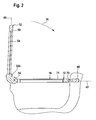
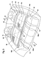
- FIG. 1 An in Fig. 1 illustrated embodiment of a Windstop raised invention for motor vehicles, especially for convertible vehicles, the body 10 in Fig. 1 is shown in detail, comprises a wind deflector 12, which in its operative position in Fig. 1 is shown and in this position over a belt line 14 of the body 10 of the motor vehicle protrudes upward, and a Windstopbasis 16, which related to a direction of travel 18 behind the standing in its operative position wind deflector 12 portion 20 of an approximately height of the belt line 14th the arranged passenger compartment opening 22 covers.
- a wind deflector 12 which in its operative position in Fig. 1 is shown and in this position over a belt line 14 of the body 10 of the motor vehicle protrudes upward
- a Windstopbasis 16 which related to a direction of travel 18 behind the standing in its operative position wind deflector 12 portion 20 of an approximately height of the belt line 14th the arranged passenger compartment opening 22 covers.
- the portion 20 of the passenger compartment opening 22 is above a rear seat system 24, which has a seat 26 and a rear seat back 28.
- the portion 20 of the passenger compartment opening 22 connects directly to the rear seat back 28 and extends in the direction of travel 18 to the wind deflector 12 also connected to body side walls 30 in the belt line 14th
- the wind deflector 12 is seated in its operative position so that this substantially immediately behind drawing in Fig. 1 Headrest, not shown, is arranged by front seats of the motor vehicle.
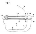
- the windstop base 16 is connected to the wind deflector 12 preferably via joints 32, for example joints 32a, 32b, 32c and 32d about an axis 34, shown in FIG Fig. 2 and 4 , pivotally connected, so that the wind deflector 12 from the in Fig. 1 and 2 shown effective position by pivoting about the axis 34 in a pivoting direction 36 of his in Fig. 1 and 2 shown effective position in an in Fig. 3 and 4 illustrated inoperative position is pivotable, in which the wind deflector 12 extends substantially parallel to the Windstopbasis 16 and is disposed substantially on this resting.
- the wind deflector 12 can again by pivoting in a pivoting direction 38 about the axis 34 in the in Fig. 1 and 2 illustrated effective position relative to the Windstopbasis move 16 in which the wind deflector 12 extends in a plane 40 which extends transversely to a plane 42 in which the Windstopbasis 16 extends.
- the plane 40 includes in the operative position of the wind deflector 12 with the plane 42 preferably an angle between about 60 ° and about 120 °, more preferably an angle between about 70 ° and about 110 °, a.
- the wind deflector 12 extends in its inoperative position, shown in FIG Fig. 3 and 4 in a plane 44 that is approximately parallel to plane 42.
- the wind deflector 12 has, as in particular in Fig. 1 and 3 shown, a wind blocker frame 50, which encloses a frame opening 52 which is closed by a wind deflector frame insert 54, wherein the wind deflector frame insert 54 is permeable to air, but wind-preventing, so that it blocks a rapid flow of air.
- the wind blocker frame 50 can be formed in one piece. But it is also conceivable, the wind deflector frame 50, as in Fig. 1 and 3 shown formed from two frame parts 56 and 58 which are pivotable about a pivot axis 60 which, for example, the central axis of the wind deflector frame 50, relative to each other.
- the two frame parts 56 and 58 In its unfolded functional position, the two frame parts 56 and 58 extend with maximum extension transversely to the direction of travel 18 in the plane 40 or 44, so that the two frame parts 56 and 58 and the wind deflector frame insert 54 in the plane 40 or 44 hold spread.
- the frame parts 56 and 58 are formed so that they are connected by hinges 62 and 64, and each C-shaped extend on both sides of the pivot axis 60, so that in the functional position, the frame opening 52 in total of the C-shaped frame members 56 and 58 enclosed and thus in particular in the region of the pivot axis 60 is not divided by struts.
- the wind stop base 16 is likewise formed from two wind stop base parts 72 and 74, which adjoin one another in the region of a parting plane 76, in which the pivot axis 60 also lies, but are preferably separable from one another.
- each of the wind stop base parts 72, 74 has a frame 70 that carries a frame insert 71.
- fixing devices 66 and 68 are preferably provided with extendable fixing pins, which engage in the case of fixing devices 66 in corresponding receptacles in the body side walls 30 and engage in the case of the fixing device 68 in a corresponding receptacle in the respective Windstopbasis Marie 72 and 74.
- the two wind stop base parts 72 and 74 are each connected via joints 32a and 32c or 32b and 32d to the corresponding frame parts 56 and 58 of the wind blocker frame 50.
- each of the hinges includes a bearing flange 80 which extends relative to the windstop base 16 from the respective frame members 56 or 58 such that the bearing flange 80 is penetrated by the axle 34 and rotatable on the respective windstop base member 72 and 74 is stored.
- the bearing flange 80 is to be driven in the sense of a pivoting movement about the axis 34, the bearing flange 80 of the joint 32c rotatably seated on a shaft 82 which is drivable by a designated as a whole with 90 drive unit.
- the drive unit 90 preferably comprises an electric drive motor 92 with a gear 94 and optionally a rotary encoder 96, wherein the output side of the rotary encoder 96, the shaft 82 protrudes from the drive unit 90, on which the bearing flange 80 is non-rotatably.
- the drive unit 90 is integrated into a front cross member 100, for example of the frame 70 of the wind stop base part 72, which for this purpose has an enlarged cross-sectional area 104, which thereby forms an interior space 106 accommodating the drive unit 90.
- the expanded cross-sectional area 104 of the front cross member 100 is immediately adjacent the parting plane 76 so that the bearing flange 80 can be located near the parting plane 76 and engages a recess 108 in the wind stop base part 72.
- a support housing 130 is provided on the wind stop base part 72, namely between the front cross member 100, a side member 110 extending to the parting plane 76 and a rear cross member 120, which is located in a frame opening 112 of the frame 70 of the wind stop base part 72 extends, preferably along the longitudinal member 110 from the front cross member 100 extends to the rear cross member 120 and is fixed to the Windstopbasisteil 72 so that the support housing 130 is seen from above under a sheet 114 which forms the frame opening 112 occlusive frame insert 71, wherein the flat material 114 on the front cross member 100, the side rail 110, the rear cross member 120 and an outer side rail 122, which form a total of the frame 70 of the Windstopbasisteils 72, fixed and held by this strained.
- the flat material 114 is also permeable to air, but designed to prevent wind, so that it also blocks a rapid flow of air, in the same way as the wind deflector frame insert 54th
- the flat material 114 can be a rigid structure, but it is also preferably provided that the flat material 114 is a textile flat material which, due to its structure, is permeable to air and at least partially translucent.
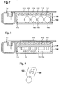
- the carrier housing 130 carries solar cells 140 on its upper side 132 facing the flat material 114, the solar cells 140 largely covering the upper side 132 of the carrier housing 130.
- the top 132 of the support housing 130 is preferably provided with a recess 134 in which the solar cells 140 are arranged and thereby protected in the top 132 are integrated.
- the solar cells 140 are thus arranged fixed relative to the wind stop base part 72.
- the solar cells 140 are also held on one of the body 10 side facing the sheet 114 and thus not immediately visible when looking at the sheet 114 from above in the direction of the body 10, as for a viewer first the visual impression of a surface of the Flat material 114 is decisive.
- the sheet material 114 is at least partially translucent, in particular in a region 116 extending over the solar cell 140, the solar cells 140 receive sufficient light to generate electricity without their surface being decisive for a viewer looking from above onto the windstop base 16 catches the eye.
- the upper side 132 of the carrier housing 130 is preferably formed by an upper housing wall 142, from which side walls 144 and 146 of the carrier housing extend, which carry a spaced from the upper housing wall 142 housing cover 148, wherein the upper housing wall 142, the side walls 144th and 146 and the housing cover 148 enclose an inner space 150 of the carrier housing 130.
- electrical energy storage 160 for example, rechargeable batteries arranged, and on the other hand, a control unit 170, which controls at least the charging of the electrical energy storage 160 through the solar cell 140, so that the solar cell 140 always when a sufficient Light incident is present, the electrical energy storage 160 recharge.
- the electrical energy storage 160 is always sufficient electrical power available to operate the drive motor 92 for pivoting the wind deflector 12 between the active and the ineffective position.
- control unit 170 is still provided with a function control 172, which controls a movement of the wind deflector 12 between the operative and inoperative position depending on, for example, a manual control unit 174 which on the front cross member 100 of the wind stop base 16, for example, the front cross member 100th the Windstopbasisteils 72, and individual buttons 176, with which individual functions of the wind deflector 12, in particular its movement from the operative position to the inoperative position and vice versa, are controllable.
- a function control 172 which controls a movement of the wind deflector 12 between the operative and inoperative position depending on, for example, a manual control unit 174 which on the front cross member 100 of the wind stop base 16, for example, the front cross member 100th the Windstopbasisteils 72, and individual buttons 176, with which individual functions of the wind deflector 12, in particular its movement from the operative position to the inoperative position and vice versa, are controllable.
- a hand control 180 is provided which preferably communicates wirelessly with the function control 172 and in turn has buttons 182, with which also the functions of the wind deflector, in particular its movement between the active and the inoperative position and vice versa, is controllable.
- the handset 180 preferably has a format corresponding to a key fob so that the driver can store it as a car key and thus at any time, even while driving, without turning over the wind deflector 12 from the inoperative position to the operative position or from the operative position the ineffective position can pivot.
- the carrier housing 130 replaceable on the Windstopbasis 16, in particular the Windstopbasisteil 72, mountable, so that depending on whether the Windstop responded self-sufficient, that is independently of an electrical system of the vehicle to be operable, the Carrier housing 130 may be mounted with the solar cells 140, the energy storage 160 and the control unit 170 or not.
- control buttons on a dashboard of the convertible vehicle whose actuation can be recognized by the vehicle function control 184 and transmitted in the form of a control signal of the function control 172.
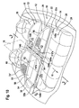
- FIG. 10 In a second embodiment of a wind stop device according to the invention, shown in FIG Fig. 10
- the longitudinal members 110'a and 110'b of the wind stop base parts 72 'and 74' form the carrier housing for the solar cells 140.
- the side members 110'a and 110'b are widened transversely to the direction of travel 18, so that they on their upper sides 190a and 190b can be provided with the solar cells 140.
- the solar cells 140 are also integrated into the upper sides 190a and 190b of the longitudinal beams 110'a and 110'b, and thus preferably give an advantageous overall impression.
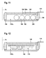
- the longitudinal beams 110'a and 110'b are designed as a widened profile tube with a top wall 194, side walls 196 and 198 and a lower removable cover 200, wherein access to the interior 192 is possible via the removable cover 200.
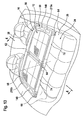
- FIG Fig. 13 In contrast to the second exemplary embodiment, elements of the wind stop base 16 are not widened, but outer regions 210a and 210b of the C-shaped frame parts 56 and 58 of the wind blocker frame 50, and these outer regions 210a, 210b carry the solar cells 140.
- portions 210a and 210b of the frame members 56 and 58 corresponding to the side rails 110'a and 110'b of the second embodiment are also provided with an inner space in which the electric energy storages 160 and the control unit 170 are arranged, with respect to their full function Embodiments of the first and second embodiments, reference is made.
- the solar cells 140 are thus not arranged on the windstop base 16 but on the movable wind deflector 12.
- This solution has the advantage that the solar cells 140 receive light optimally both in the operative position and in the inoperative position, since no covering of same by the wind deflector 12 takes place in the inoperative position, as in the first and second embodiments of the case is.
- the electrical energy storage 160 may still be in the Windstopbasis 16, for example in the Windstopbasis kind 72 and 74, for example, in the front cross members 100a and 100b, be arranged so that the weight of the electric energy storage 160 when moving of the wind deflector 12 from the inoperative to the operative position requires no higher power of the drive motor 92.
- the weight of the solar cells 140 in contrast to the weight of the electrical energy storage 160 has no significance, the weight increase in the region of the frame 50 of the wind deflector 12 by arranging the solar cell 140 without or only little relevance.
Landscapes
- Engineering & Computer Science (AREA)
- Mechanical Engineering (AREA)
- Photovoltaic Devices (AREA)
- Operating, Guiding And Securing Of Roll- Type Closing Members (AREA)
- Devices Affording Protection Of Roads Or Walls For Sound Insulation (AREA)
- Refuge Islands, Traffic Blockers, Or Guard Fence (AREA)
Claims (40)
- Système déflecteur de vent destiné à des véhicules automobiles, en particulier à des véhicules cabriolet, comprenant une base déflectrice de vent (16) disposée à hauteur d'une ligne de ceinture (14) d'une carrosserie (10) et une cloison coupe-vent (12) reliée de manière articulée à la base déflectrice de vent (16), laquelle cloison coupe-vent peut pivoter d'une position inactive s'étendant approximativement à hauteur de la ligne de ceinture (14) de la carrosserie (10) dans une position active se soulevant au-dessus de la ligne de ceinture (14) et s'étendant de manière transversale par rapport à cette dernière, et comprenant une unité d'entraînement (90) électrique, à l'aide de laquelle la cloison coupe-vent (12) peut être déplacée par rapport à la base déflectrice de vent (16) entre la position inactive et la position active,
caractérisé en ce que le système déflecteur de vent est pourvu d'un accumulateur d'énergie (160) électrique, qui fournit de l'énergie électrique servant à faire fonctionner l'unité d'entraînement (90) électrique. - Système déflecteur de vent selon la revendication 1, caractérisé en ce que le système déflecteur de vent est pourvu de cellules solaires (140), à l'aide desquelles l'au moins un accumulateur d'énergie (160) électrique peut être rechargé.
- Système déflecteur de vent selon la revendication 2, caractérisé en ce que les cellules solaires (140) sont disposées sur un côté, opposé à la carrosserie (10), du système déflecteur de vent.
- Système déflecteur de vent selon l'une quelconque des revendications 2 à 3,
caractérisé en ce que les cellules solaires (140) sont disposées dans la zone de la cloison coupe-vent (12). - Système déflecteur de vent selon la revendication 4, caractérisé en ce que la cloison coupe-vent (12) présente un cadre (50), et en ce que les cellules solaires (140) sont maintenues au niveau du cadre (50) de la cloison coupe-vent (12).
- Système déflecteur de vent selon la revendication 5, caractérisé en ce que les cellules solaires (140) sont disposées au niveau du cadre (50).
- Système déflecteur de vent selon la revendication 6, caractérisé en ce que les cellules solaires (140) sont disposées dans une zone de cadre (210).
- Système déflecteur de vent selon l'une quelconque des revendications 1 à 3, caractérisé en ce que les cellules solaires (140) sont disposées dans la zone de la base déflectrice de vent (16).
- Système déflecteur de vent selon la revendication 8, caractérisé en ce que les cellules solaires (140) sont disposées sur un côté, opposé à la carrosserie (10), de la base déflectrice de vent (16).
- Système déflecteur de vent selon la revendication 8 ou 9, caractérisé en ce que la base déflectrice de vent (16) présente un cadre (70), et en ce que les cellules solaires (140) sont maintenues au niveau du cadre (70).
- Système déflecteur de vent selon la revendication 10, caractérisé en ce que les cellules solaires (140) sont disposées au niveau du cadre (70).
- Système déflecteur de vent selon la revendication 11, caractérisé en ce que les cellules solaires (140) sont disposées au niveau d'un support de cadre (110') du cadre de la base déflectrice de vent.
- Système déflecteur de vent selon l'une quelconque des revendications 10 à 12, caractérisé en ce que le cadre (70) présente des ouvertures de cadre (112), et en ce que les cellules solaires (140) sont disposées dans la zone des ouvertures de cadre (112).
- Système déflecteur de vent selon la revendication 13, caractérisé en ce que les cellules solaires (140) sont dissimulées par un matériau plat (114) recouvrant les ouvertures de cadre (112).
- Système déflecteur de vent selon la revendication 14, caractérisé en ce que le matériau plat (114) est au moins en partie perméable à la lumière.
- Système déflecteur de vent selon l'une quelconque des revendications 14 à 15,
caractérisé en ce que le matériau plat (114) est un matériau plat textile. - Système déflecteur de vent selon la revendication 15 ou 16, caractérisé en ce que le matériau plat (114) présente, dans sa zone (116) recouvrant les cellules solaires (140), une perméabilité à la lumière élevée.
- Système déflecteur de vent selon la revendication 17, caractérisé en ce que le matériau plat (114) présente, dans sa zone (116) recouvrant les cellules solaires (140), une densité de fil inférieure par rapport à celle d'autres zones.
- Système déflecteur de vent selon l'une quelconque des revendications 8 à 18, caractérisé en ce que les cellules solaires (140) sont disposées dans un boîtier de support (130).
- Système déflecteur de vent selon la revendication 19, caractérisé en ce que les cellules solaires (140) sont intégrées dans un côté supérieur (132) du boîtier de support (130).
- Système déflecteur de vent selon la revendication 19 ou 20, caractérisé en ce que le boîtier de support (130) est fixé au niveau du cadre (70).
- Système déflecteur de vent selon la revendication 21, caractérisé en ce que le boîtier de support (130) est fixé de manière amovible au niveau du cadre (70).
- Système déflecteur de vent selon l'une quelconque des revendications 19 à 22, caractérisé en ce que l'au moins un accumulateur d'énergie (160) électrique est disposé dans le boîtier de support (130).
- Système déflecteur de vent selon l'une quelconque des revendications 19 à 23, caractérisé en ce que la base déflectrice de vent (16) présente deux parties de base déflectrice de vent (72, 74), et en ce que le boîtier de support (130) est maintenu pour les cellules solaires (140) au moins au niveau d'une des parties de base déflectrice de vent (72, 74).
- Système déflecteur de vent selon l'une quelconque des revendications 8 à 18, caractérisé en ce que le cadre (70) de la base déflectrice de vent (16) forme une zone de support (110'a, b) pour les cellules solaires (140).
- Système déflecteur de vent selon l'une quelconque des revendications 10 à 25,
caractérisé en ce que le cadre (70) forme un boîtier (110'a, b) pour l'accumulateur d'énergie (160) électrique. - Système déflecteur de vent selon l'une quelconque des revendications précédentes, caractérisé en ce que le système déflecteur de vent comprend une unité de commande (170), qui surveille au moins un état de charge de l'au moins un accumulateur d'énergie (160).
- Système déflecteur de vent selon la revendication 27, caractérisé en ce que l'unité de commande (170) comprend une commande de fonction (172) pour la cloison coupe-vent (12).
- Système déflecteur de vent selon la revendication 28, caractérisé en ce que la commande de fonction (172) communique avec une unité d'utilisation manuelle (174, 180).
- Système déflecteur de vent selon la revendication 29, caractérisé en ce que l'unité d'utilisation manuelle (174) est disposée de manière fixe au niveau du système déflecteur de vent.
- Système déflecteur de vent selon la revendication 19 et selon l'une quelconque des revendications 27 à 30, caractérisé en ce que l'unité de commande (170) est disposée dans le boîtier de support (130).
- Système déflecteur de vent selon l'une quelconque des revendications 27 à 31, caractérisé en ce que l'unité de commande (170) est disposée dans un cadre (50, 70) du système déflecteur de vent.
- Système déflecteur de vent selon l'une quelconque des revendications 29 à 32, caractérisé en ce que l'unité d'utilisation manuelle (174) est disposée au niveau de la base déflectrice de vent (16).
- Système déflecteur de base selon la revendication 19 et selon l'une quelconque des revendications 29 à 33, caractérisé en ce que l'unité d'utilisation manuelle (174) est disposée dans le boîtier de support (130).
- Système déflecteur de vent selon l'une quelconque des revendications 29 à 34, caractérisé en ce que l'unité d'utilisation manuelle (174) est disposée au niveau d'un cadre (50, 70) du système déflecteur de vent.
- Système déflecteur de vent selon l'une quelconque des revendications 29 à 35, caractérisé en ce que la commande de fonction (172) communique sans fil avec l'unité d'utilisation manuelle (180).
- Système déflecteur de vent selon l'une quelconque des revendications précédentes, caractérisé en ce que l'unité d'entraînement (90) électrique est disposée au niveau de la base déflectrice de vent (16).
- Système déflecteur de vent selon l'une quelconque des revendications 1 à 36, caractérisé en ce que l'unité d'entraînement (90) électrique est intégrée dans la base déflectrice de vent (16).
- Système déflecteur de vent selon la revendication 38, caractérisé en ce que la base déflectrice de vent (16) présente un support (100), et en ce que l'unité d'entraînement (90) électrique est intégrée dans une zone du support (100) de la base déflectrice de vent (16).
- Système déflecteur de vent selon l'une quelconque des revendications 38 et 39, caractérisé en ce que la base déflectrice de vent présente deux parties de base déflectrice de vent (72, 74), et en ce que l'unité d'entraînement (90) électrique est intégrée dans l'une des parties de base déflectrice de vent (72, 74).
Applications Claiming Priority (1)
| Application Number | Priority Date | Filing Date | Title |
|---|---|---|---|
| DE102006043626A DE102006043626A1 (de) | 2006-09-12 | 2006-09-12 | Windstopeinrichtung |
Publications (3)
| Publication Number | Publication Date |
|---|---|
| EP1900563A2 EP1900563A2 (fr) | 2008-03-19 |
| EP1900563A3 EP1900563A3 (fr) | 2010-03-24 |
| EP1900563B1 true EP1900563B1 (fr) | 2015-11-04 |
Family
ID=38793011
Family Applications (1)
| Application Number | Title | Priority Date | Filing Date |
|---|---|---|---|
| EP07017628.4A Not-in-force EP1900563B1 (fr) | 2006-09-12 | 2007-09-08 | Dispositif pare vent |
Country Status (3)
| Country | Link |
|---|---|
| US (1) | US7766415B2 (fr) |
| EP (1) | EP1900563B1 (fr) |
| DE (1) | DE102006043626A1 (fr) |
Families Citing this family (4)
| Publication number | Priority date | Publication date | Assignee | Title |
|---|---|---|---|---|
| ATE512014T1 (de) * | 2009-04-30 | 2011-06-15 | Fiat Group Automobiles Spa | Windschott für zweisitziges cabriolet |
| DE102009035335A1 (de) | 2009-07-21 | 2011-01-27 | Scambia Industrial Developments Aktiengesellschaft | Antriebseinheit für eine Windstopeinrichtung |
| DE102014100978A1 (de) * | 2014-01-28 | 2015-07-30 | Scambia Holdings Cyprus Limited | Windstopeinrichtung |
| KR20220166515A (ko) | 2021-06-10 | 2022-12-19 | 현대자동차주식회사 | 차량의 파티션부 구조 |
Family Cites Families (41)
| Publication number | Priority date | Publication date | Assignee | Title |
|---|---|---|---|---|
| JPS6022564A (ja) * | 1983-07-13 | 1985-02-05 | Nippon Denso Co Ltd | 車両用エアスポイラ |
| JPS6022565A (ja) * | 1983-07-13 | 1985-02-05 | Nippon Denso Co Ltd | 車両用エアスポイラ |
| JPS6022566A (ja) * | 1983-07-13 | 1985-02-05 | Nippon Denso Co Ltd | 車両用エアスポイラ |
| JPS60234076A (ja) * | 1984-05-04 | 1985-11-20 | Nippon Soken Inc | 車両用エアスポイラ |
| JPS60236854A (ja) * | 1984-05-10 | 1985-11-25 | Nippon Denso Co Ltd | 車両用エアスポイラ |
| DE3537644C1 (de) * | 1985-10-23 | 1987-04-16 | Ford Werke Ag | Abdeckung fuer den Fahrgastraum eines Kabrioletts |
| DE3611750A1 (de) * | 1986-04-08 | 1987-10-22 | Braun Jean | Kinetische primaere energie nutzungsvorrichtungen |
| DE3844844C3 (de) * | 1987-11-13 | 1998-07-23 | Daimler Benz Ag | Windschutz für Cabriolets |
| JPH01187880A (ja) * | 1988-01-14 | 1989-07-27 | Hitachi Micro Comput Eng Ltd | 太陽電池電源 |
| US5318337A (en) * | 1989-04-28 | 1994-06-07 | Mercedes-Benz Ag | Windscreen arrangement for a convertible |
| DE4018862A1 (de) * | 1990-06-13 | 1992-01-02 | Claus Juerich | Cabriolet mit einem windschutz |
| DE4037705C1 (fr) * | 1990-11-27 | 1991-10-24 | Mercedes-Benz Aktiengesellschaft, 7000 Stuttgart, De | |
| DE4037704C1 (fr) * | 1990-11-27 | 1992-03-12 | Mercedes-Benz Aktiengesellschaft, 7000 Stuttgart, De | |
| DE4119530A1 (de) * | 1991-06-13 | 1992-12-17 | Bayerische Motoren Werke Ag | Windschutz fuer cabriolets oder aehnliche fahrzeuge |
| DE69208073T2 (de) * | 1992-01-25 | 1996-06-27 | Jaguar Cars | Kraftfahrzeug |
| DE9206644U1 (de) * | 1992-05-15 | 1992-07-23 | Oris-Metallbau KG Hans Riehle, 7141 Möglingen | Rolloanordnung bei Kraftwagen, insbesondere bei Cabrios |
| US5344361A (en) * | 1992-06-03 | 1994-09-06 | Matthias Jan H | Sun roof vent |
| FR2694312B1 (fr) * | 1992-07-28 | 1994-10-28 | Lefaucheur Joel | Agencement à dispositif pivotant entre deux positions, tel qu'un agencement de barrière pivotant entre une position d'interdiction de l'accès à une zone réservée et une position de dégagement de l'accès. |
| DE4315201A1 (de) * | 1992-07-30 | 1994-02-03 | Oris Metallbau Kg Riehle H | Windstop für Cabrios (F3/92) |
| DE4235416A1 (de) * | 1992-10-21 | 1994-04-28 | Karsten Javs | Vorrichtung zur Verringerung von Luftströmungen im Frontsitzbereich bei offenen Fahrzeugen mit feststehendem Überrollbügel (Windschutz) |
| JPH06156327A (ja) * | 1992-11-25 | 1994-06-03 | Toyota Motor Corp | ソーラーカーのタイヤカバー |
| DE4311240C1 (de) * | 1993-04-06 | 1994-04-07 | Daimler Benz Ag | Windschott für ein Cabriolet mit einem Verdeckkastendeckel |
| DE4338102C2 (de) * | 1993-11-08 | 1996-05-09 | Daimler Benz Ag | Windschott für einen offenen Personenkraftwagen |
| DE4446769A1 (de) * | 1994-12-24 | 1996-06-27 | Karmann Gmbh W | Windabweisende Abdeckung für ein Cabriolet |
| DE19535593A1 (de) * | 1995-09-25 | 1997-03-27 | Bayerische Motoren Werke Ag | Cabriolet mit einem Windschott |
| DE19545405A1 (de) * | 1995-12-06 | 1997-06-12 | Porsche Ag | Windschott für ein Cabriolet |
| DE29615342U1 (de) * | 1996-09-03 | 1996-10-17 | Zalzar GmbH, 80807 München | Windschott für ein Cabriolet |
| US5905356A (en) * | 1996-11-18 | 1999-05-18 | Wells; Gilbert Michael | Solar powered charger for vehicular accessories and cordless tools |
| US5814906A (en) * | 1996-12-09 | 1998-09-29 | Spencer; Jerald C. | Power supply for portable computers and other electronic devices |
| DE19937877B4 (de) * | 1999-05-21 | 2006-09-21 | Müller, Hermann-Frank | Kunststoffblenden-Anordnung für Fahrzeuge |
| DE10053701A1 (de) * | 2000-10-24 | 2002-05-08 | Oris Fahrzeugteile Riehle H | Windstopeinrichtung |
| DE10061562A1 (de) * | 2000-12-04 | 2002-06-13 | Oris Fahrzeugteile Riehle H | Windschott |
| DE10063770B4 (de) * | 2000-12-21 | 2007-08-02 | Daimlerchrysler Ag | Windschutzvorrichtung für ein Kraftfahrzeug |
| USD479191S1 (en) * | 2002-08-16 | 2003-09-02 | Icp Global Technologies Inc. | Briefcase solar power generator |
| USD489680S1 (en) * | 2003-06-27 | 2004-05-11 | Smart Solar Limited | Battery charger |
| US7226118B2 (en) * | 2004-06-29 | 2007-06-05 | Scambia Industrial Developments Aktiengesellschaft | Wind stop device |
| DE102004037482A1 (de) * | 2004-07-27 | 2006-02-16 | Oris Fahrzeugteile Hans Riehle Gmbh | Windstopeinrichtung |
| US7486044B2 (en) * | 2004-11-30 | 2009-02-03 | Motorola, Inc. | Light detection power system and method for same |
| DE102004061758B4 (de) * | 2004-12-22 | 2015-08-13 | Volkswagen Ag | Windstopeinrichtung |
| USD530036S1 (en) * | 2005-02-02 | 2006-10-10 | Wolf Strycker | Solar down-light |
| US20080072949A1 (en) * | 2006-09-19 | 2008-03-27 | Rowell Sandra L | Solar energy charging system on windshield |
-
2006
- 2006-09-12 DE DE102006043626A patent/DE102006043626A1/de not_active Ceased
-
2007
- 2007-09-08 EP EP07017628.4A patent/EP1900563B1/fr not_active Not-in-force
- 2007-09-10 US US11/900,408 patent/US7766415B2/en not_active Expired - Fee Related
Also Published As
| Publication number | Publication date |
|---|---|
| DE102006043626A1 (de) | 2008-03-27 |
| EP1900563A3 (fr) | 2010-03-24 |
| EP1900563A2 (fr) | 2008-03-19 |
| US20080088153A1 (en) | 2008-04-17 |
| US7766415B2 (en) | 2010-08-03 |
Similar Documents
| Publication | Publication Date | Title |
|---|---|---|
| EP0850792B1 (fr) | Véhicule automobile | |
| EP0826537B1 (fr) | Construction de toit pour véhicule, en particulier pour véhicule de passagers | |
| DE102005052030B4 (de) | Klappbare Anzeigeeinrichtung mit Abdeckung, insbesondere für Kraftfahrzeuge | |
| EP1897737B1 (fr) | Déflecteur d'air | |
| DE10111453A1 (de) | Sonnendachanordnung für Fahrzeuge | |
| DE60033129T2 (de) | Abnehmbares dachmodul für einen kraftfahrzeug-fahrgastraum und mit solchem modul ausgerüstetes kraftfahrzeug | |
| DE102008064054A1 (de) | Integrierte Beschattungsanordnung für ein Fahrzeugfenster | |
| DE102005028193A1 (de) | Freiluftsystem für Kraftfahrzeuge | |
| EP0860311A1 (fr) | Coffre de stockage variable pour capote de cabriolet | |
| DE60036533T2 (de) | Abnehmbares verdeckmodul für den fahrgastraum eines kraftfahrzeuges und kraftfahrzeug ausgerüstet mit einem solchen modul | |
| EP2066510A2 (fr) | Module de revêtement de toit pour véhicules automobiles | |
| EP1900563B1 (fr) | Dispositif pare vent | |
| EP0943474A2 (fr) | Toit rigide escamotable pour voiture cabriolet | |
| DE19737259A1 (de) | Hardtop-Fahrzeug | |
| DE19856741C2 (de) | Laderaumabdeckung bzw. Hutablage mit beweglichen Eckstücken | |
| DE102013105472B4 (de) | Laderaumabdeckung | |
| EP3573862B1 (fr) | Automobile | |
| EP1281552A1 (fr) | Véhicule avec un toit escamotable | |
| EP3853110B1 (fr) | Véhicule électrique compact à trois roues | |
| DE10256347B4 (de) | Schutzvorrichtung für einen Laderaum eines Kraftfahrzeugs | |
| DE102006053049A1 (de) | Staufach mit einer Abdeckeinrichtung | |
| DE202012101614U1 (de) | PKW-Ladevorrichtung zum Ein- und Ausladen eines Kleinfahrzeugs sowie Kleinfahrzeug | |
| DE102005031722B4 (de) | Abdeckvorrichtung für einen Laderaum eines Fahrzeugs | |
| EP1878415A2 (fr) | Dispositif d'actionnement supplémentaire pour fauteuils roulants manuels | |
| EP1145908B1 (fr) | Plateau de chargement |
Legal Events
| Date | Code | Title | Description |
|---|---|---|---|
| PUAI | Public reference made under article 153(3) epc to a published international application that has entered the european phase |
Free format text: ORIGINAL CODE: 0009012 |
|
| AK | Designated contracting states |
Kind code of ref document: A2 Designated state(s): AT BE BG CH CY CZ DE DK EE ES FI FR GB GR HU IE IS IT LI LT LU LV MC MT NL PL PT RO SE SI SK TR |
|
| AX | Request for extension of the european patent |
Extension state: AL BA HR MK YU |
|
| PUAL | Search report despatched |
Free format text: ORIGINAL CODE: 0009013 |
|
| AK | Designated contracting states |
Kind code of ref document: A3 Designated state(s): AT BE BG CH CY CZ DE DK EE ES FI FR GB GR HU IE IS IT LI LT LU LV MC MT NL PL PT RO SE SI SK TR |
|
| AX | Request for extension of the european patent |
Extension state: AL BA HR MK RS |
|
| 17P | Request for examination filed |
Effective date: 20100914 |
|
| AKX | Designation fees paid |
Designated state(s): AT BE BG CH CY CZ DE DK EE ES FI FR GB GR HU IE IS IT LI LT LU LV MC MT NL PL PT RO SE SI SK TR |
|
| RAP1 | Party data changed (applicant data changed or rights of an application transferred) |
Owner name: SCAMBIA HOLDINGS CYPRUS LIMITED |
|
| GRAP | Despatch of communication of intention to grant a patent |
Free format text: ORIGINAL CODE: EPIDOSNIGR1 |
|
| INTG | Intention to grant announced |
Effective date: 20150414 |
|
| INTG | Intention to grant announced |
Effective date: 20150421 |
|
| GRAS | Grant fee paid |
Free format text: ORIGINAL CODE: EPIDOSNIGR3 |
|
| GRAA | (expected) grant |
Free format text: ORIGINAL CODE: 0009210 |
|
| AK | Designated contracting states |
Kind code of ref document: B1 Designated state(s): AT BE BG CH CY CZ DE DK EE ES FI FR GB GR HU IE IS IT LI LT LU LV MC MT NL PL PT RO SE SI SK TR |
|
| REG | Reference to a national code |
Ref country code: GB Ref legal event code: FG4D Free format text: NOT ENGLISH |
|
| REG | Reference to a national code |
Ref country code: CH Ref legal event code: EP |
|
| REG | Reference to a national code |
Ref country code: AT Ref legal event code: REF Ref document number: 758931 Country of ref document: AT Kind code of ref document: T Effective date: 20151115 |
|
| REG | Reference to a national code |
Ref country code: IE Ref legal event code: FG4D Free format text: LANGUAGE OF EP DOCUMENT: GERMAN |
|
| REG | Reference to a national code |
Ref country code: DE Ref legal event code: R096 Ref document number: 502007014364 Country of ref document: DE |
|
| REG | Reference to a national code |
Ref country code: NL Ref legal event code: MP Effective date: 20151104 |
|
| REG | Reference to a national code |
Ref country code: LT Ref legal event code: MG4D |
|
| PG25 | Lapsed in a contracting state [announced via postgrant information from national office to epo] |
Ref country code: LT Free format text: LAPSE BECAUSE OF FAILURE TO SUBMIT A TRANSLATION OF THE DESCRIPTION OR TO PAY THE FEE WITHIN THE PRESCRIBED TIME-LIMIT Effective date: 20151104 Ref country code: NL Free format text: LAPSE BECAUSE OF FAILURE TO SUBMIT A TRANSLATION OF THE DESCRIPTION OR TO PAY THE FEE WITHIN THE PRESCRIBED TIME-LIMIT Effective date: 20151104 Ref country code: IS Free format text: LAPSE BECAUSE OF FAILURE TO SUBMIT A TRANSLATION OF THE DESCRIPTION OR TO PAY THE FEE WITHIN THE PRESCRIBED TIME-LIMIT Effective date: 20160304 Ref country code: ES Free format text: LAPSE BECAUSE OF FAILURE TO SUBMIT A TRANSLATION OF THE DESCRIPTION OR TO PAY THE FEE WITHIN THE PRESCRIBED TIME-LIMIT Effective date: 20151104 Ref country code: IT Free format text: LAPSE BECAUSE OF FAILURE TO SUBMIT A TRANSLATION OF THE DESCRIPTION OR TO PAY THE FEE WITHIN THE PRESCRIBED TIME-LIMIT Effective date: 20151104 |
|
| PG25 | Lapsed in a contracting state [announced via postgrant information from national office to epo] |
Ref country code: SE Free format text: LAPSE BECAUSE OF FAILURE TO SUBMIT A TRANSLATION OF THE DESCRIPTION OR TO PAY THE FEE WITHIN THE PRESCRIBED TIME-LIMIT Effective date: 20151104 Ref country code: LV Free format text: LAPSE BECAUSE OF FAILURE TO SUBMIT A TRANSLATION OF THE DESCRIPTION OR TO PAY THE FEE WITHIN THE PRESCRIBED TIME-LIMIT Effective date: 20151104 Ref country code: PL Free format text: LAPSE BECAUSE OF FAILURE TO SUBMIT A TRANSLATION OF THE DESCRIPTION OR TO PAY THE FEE WITHIN THE PRESCRIBED TIME-LIMIT Effective date: 20151104 Ref country code: GR Free format text: LAPSE BECAUSE OF FAILURE TO SUBMIT A TRANSLATION OF THE DESCRIPTION OR TO PAY THE FEE WITHIN THE PRESCRIBED TIME-LIMIT Effective date: 20160205 Ref country code: FI Free format text: LAPSE BECAUSE OF FAILURE TO SUBMIT A TRANSLATION OF THE DESCRIPTION OR TO PAY THE FEE WITHIN THE PRESCRIBED TIME-LIMIT Effective date: 20151104 Ref country code: PT Free format text: LAPSE BECAUSE OF FAILURE TO SUBMIT A TRANSLATION OF THE DESCRIPTION OR TO PAY THE FEE WITHIN THE PRESCRIBED TIME-LIMIT Effective date: 20160304 |
|
| PG25 | Lapsed in a contracting state [announced via postgrant information from national office to epo] |
Ref country code: CZ Free format text: LAPSE BECAUSE OF FAILURE TO SUBMIT A TRANSLATION OF THE DESCRIPTION OR TO PAY THE FEE WITHIN THE PRESCRIBED TIME-LIMIT Effective date: 20151104 |
|
| REG | Reference to a national code |
Ref country code: DE Ref legal event code: R097 Ref document number: 502007014364 Country of ref document: DE |
|
| PG25 | Lapsed in a contracting state [announced via postgrant information from national office to epo] |
Ref country code: RO Free format text: LAPSE BECAUSE OF FAILURE TO SUBMIT A TRANSLATION OF THE DESCRIPTION OR TO PAY THE FEE WITHIN THE PRESCRIBED TIME-LIMIT Effective date: 20151104 Ref country code: SK Free format text: LAPSE BECAUSE OF FAILURE TO SUBMIT A TRANSLATION OF THE DESCRIPTION OR TO PAY THE FEE WITHIN THE PRESCRIBED TIME-LIMIT Effective date: 20151104 Ref country code: EE Free format text: LAPSE BECAUSE OF FAILURE TO SUBMIT A TRANSLATION OF THE DESCRIPTION OR TO PAY THE FEE WITHIN THE PRESCRIBED TIME-LIMIT Effective date: 20151104 Ref country code: DK Free format text: LAPSE BECAUSE OF FAILURE TO SUBMIT A TRANSLATION OF THE DESCRIPTION OR TO PAY THE FEE WITHIN THE PRESCRIBED TIME-LIMIT Effective date: 20151104 |
|
| PLBE | No opposition filed within time limit |
Free format text: ORIGINAL CODE: 0009261 |
|
| STAA | Information on the status of an ep patent application or granted ep patent |
Free format text: STATUS: NO OPPOSITION FILED WITHIN TIME LIMIT |
|
| REG | Reference to a national code |
Ref country code: FR Ref legal event code: PLFP Year of fee payment: 10 |
|
| 26N | No opposition filed |
Effective date: 20160805 |
|
| PG25 | Lapsed in a contracting state [announced via postgrant information from national office to epo] |
Ref country code: SI Free format text: LAPSE BECAUSE OF FAILURE TO SUBMIT A TRANSLATION OF THE DESCRIPTION OR TO PAY THE FEE WITHIN THE PRESCRIBED TIME-LIMIT Effective date: 20151104 |
|
| PG25 | Lapsed in a contracting state [announced via postgrant information from national office to epo] |
Ref country code: BE Free format text: LAPSE BECAUSE OF NON-PAYMENT OF DUE FEES Effective date: 20160930 |
|
| PG25 | Lapsed in a contracting state [announced via postgrant information from national office to epo] |
Ref country code: MC Free format text: LAPSE BECAUSE OF FAILURE TO SUBMIT A TRANSLATION OF THE DESCRIPTION OR TO PAY THE FEE WITHIN THE PRESCRIBED TIME-LIMIT Effective date: 20151104 |
|
| REG | Reference to a national code |
Ref country code: CH Ref legal event code: PL |
|
| REG | Reference to a national code |
Ref country code: IE Ref legal event code: MM4A |
|
| PG25 | Lapsed in a contracting state [announced via postgrant information from national office to epo] |
Ref country code: CH Free format text: LAPSE BECAUSE OF NON-PAYMENT OF DUE FEES Effective date: 20160930 Ref country code: LI Free format text: LAPSE BECAUSE OF NON-PAYMENT OF DUE FEES Effective date: 20160930 Ref country code: IE Free format text: LAPSE BECAUSE OF NON-PAYMENT OF DUE FEES Effective date: 20160908 |
|
| PG25 | Lapsed in a contracting state [announced via postgrant information from national office to epo] |
Ref country code: LU Free format text: LAPSE BECAUSE OF NON-PAYMENT OF DUE FEES Effective date: 20160908 |
|
| REG | Reference to a national code |
Ref country code: FR Ref legal event code: PLFP Year of fee payment: 11 |
|
| REG | Reference to a national code |
Ref country code: AT Ref legal event code: MM01 Ref document number: 758931 Country of ref document: AT Kind code of ref document: T Effective date: 20160908 |
|
| REG | Reference to a national code |
Ref country code: BE Ref legal event code: MM Effective date: 20160930 |
|
| REG | Reference to a national code |
Ref country code: DE Ref legal event code: R081 Ref document number: 502007014364 Country of ref document: DE Owner name: ACPS AUTOMOTIVE GMBH, DE Free format text: FORMER OWNER: SCAMBIA HOLDINGS CYPRUS LTD., LIMASSOL, CY Ref country code: DE Ref legal event code: R082 Ref document number: 502007014364 Country of ref document: DE Representative=s name: HOEGER, STELLRECHT & PARTNER PATENTANWAELTE MB, DE Ref country code: DE Ref legal event code: R081 Ref document number: 502007014364 Country of ref document: DE Owner name: BOSAL ACPS HOLDING 2 B.V., NL Free format text: FORMER OWNER: SCAMBIA HOLDINGS CYPRUS LTD., LIMASSOL, CY |
|
| PG25 | Lapsed in a contracting state [announced via postgrant information from national office to epo] |
Ref country code: AT Free format text: LAPSE BECAUSE OF NON-PAYMENT OF DUE FEES Effective date: 20160908 |
|
| PG25 | Lapsed in a contracting state [announced via postgrant information from national office to epo] |
Ref country code: HU Free format text: LAPSE BECAUSE OF FAILURE TO SUBMIT A TRANSLATION OF THE DESCRIPTION OR TO PAY THE FEE WITHIN THE PRESCRIBED TIME-LIMIT; INVALID AB INITIO Effective date: 20070908 Ref country code: CY Free format text: LAPSE BECAUSE OF FAILURE TO SUBMIT A TRANSLATION OF THE DESCRIPTION OR TO PAY THE FEE WITHIN THE PRESCRIBED TIME-LIMIT Effective date: 20151104 |
|
| PG25 | Lapsed in a contracting state [announced via postgrant information from national office to epo] |
Ref country code: MT Free format text: LAPSE BECAUSE OF FAILURE TO SUBMIT A TRANSLATION OF THE DESCRIPTION OR TO PAY THE FEE WITHIN THE PRESCRIBED TIME-LIMIT Effective date: 20151104 Ref country code: TR Free format text: LAPSE BECAUSE OF FAILURE TO SUBMIT A TRANSLATION OF THE DESCRIPTION OR TO PAY THE FEE WITHIN THE PRESCRIBED TIME-LIMIT Effective date: 20151104 |
|
| PG25 | Lapsed in a contracting state [announced via postgrant information from national office to epo] |
Ref country code: BG Free format text: LAPSE BECAUSE OF FAILURE TO SUBMIT A TRANSLATION OF THE DESCRIPTION OR TO PAY THE FEE WITHIN THE PRESCRIBED TIME-LIMIT Effective date: 20151104 |
|
| REG | Reference to a national code |
Ref country code: GB Ref legal event code: 732E Free format text: REGISTERED BETWEEN 20180719 AND 20180725 |
|
| REG | Reference to a national code |
Ref country code: FR Ref legal event code: PLFP Year of fee payment: 12 |
|
| REG | Reference to a national code |
Ref country code: DE Ref legal event code: R082 Ref document number: 502007014364 Country of ref document: DE Representative=s name: HOEGER, STELLRECHT & PARTNER PATENTANWAELTE MB, DE Ref country code: DE Ref legal event code: R081 Ref document number: 502007014364 Country of ref document: DE Owner name: ACPS AUTOMOTIVE GMBH, DE Free format text: FORMER OWNER: BOSAL ACPS HOLDING 2 B.V., VIANEN, NL |
|
| PGFP | Annual fee paid to national office [announced via postgrant information from national office to epo] |
Ref country code: DE Payment date: 20190918 Year of fee payment: 13 Ref country code: FR Payment date: 20190926 Year of fee payment: 13 |
|
| PGFP | Annual fee paid to national office [announced via postgrant information from national office to epo] |
Ref country code: GB Payment date: 20190925 Year of fee payment: 13 |
|
| REG | Reference to a national code |
Ref country code: DE Ref legal event code: R119 Ref document number: 502007014364 Country of ref document: DE |
|
| GBPC | Gb: european patent ceased through non-payment of renewal fee |
Effective date: 20200908 |
|
| PG25 | Lapsed in a contracting state [announced via postgrant information from national office to epo] |
Ref country code: DE Free format text: LAPSE BECAUSE OF NON-PAYMENT OF DUE FEES Effective date: 20210401 Ref country code: FR Free format text: LAPSE BECAUSE OF NON-PAYMENT OF DUE FEES Effective date: 20200930 |
|
| PG25 | Lapsed in a contracting state [announced via postgrant information from national office to epo] |
Ref country code: GB Free format text: LAPSE BECAUSE OF NON-PAYMENT OF DUE FEES Effective date: 20200908 |