EP1897799A2 - Einrichtung für die dynamische Stabilisierung eines U-Bootes - Google Patents
Einrichtung für die dynamische Stabilisierung eines U-Bootes Download PDFInfo
- Publication number
- EP1897799A2 EP1897799A2 EP07290867A EP07290867A EP1897799A2 EP 1897799 A2 EP1897799 A2 EP 1897799A2 EP 07290867 A EP07290867 A EP 07290867A EP 07290867 A EP07290867 A EP 07290867A EP 1897799 A2 EP1897799 A2 EP 1897799A2
- Authority
- EP
- European Patent Office
- Prior art keywords
- wing
- axis
- roll
- machine
- rudder
- Prior art date
- Legal status (The legal status is an assumption and is not a legal conclusion. Google has not performed a legal analysis and makes no representation as to the accuracy of the status listed.)
- Granted
Links
Images




Classifications
-
- B—PERFORMING OPERATIONS; TRANSPORTING
- B63—SHIPS OR OTHER WATERBORNE VESSELS; RELATED EQUIPMENT
- B63B—SHIPS OR OTHER WATERBORNE VESSELS; EQUIPMENT FOR SHIPPING
- B63B21/00—Tying-up; Shifting, towing, or pushing equipment; Anchoring
- B63B21/56—Towing or pushing equipment
- B63B21/66—Equipment specially adapted for towing underwater objects or vessels, e.g. fairings for tow-cables
-
- B—PERFORMING OPERATIONS; TRANSPORTING
- B63—SHIPS OR OTHER WATERBORNE VESSELS; RELATED EQUIPMENT
- B63G—OFFENSIVE OR DEFENSIVE ARRANGEMENTS ON VESSELS; MINE-LAYING; MINE-SWEEPING; SUBMARINES; AIRCRAFT CARRIERS
- B63G8/00—Underwater vessels, e.g. submarines; Equipment specially adapted therefor
- B63G8/14—Control of attitude or depth
- B63G8/18—Control of attitude or depth by hydrofoils
-
- B—PERFORMING OPERATIONS; TRANSPORTING
- B63—SHIPS OR OTHER WATERBORNE VESSELS; RELATED EQUIPMENT
- B63G—OFFENSIVE OR DEFENSIVE ARRANGEMENTS ON VESSELS; MINE-LAYING; MINE-SWEEPING; SUBMARINES; AIRCRAFT CARRIERS
- B63G8/00—Underwater vessels, e.g. submarines; Equipment specially adapted therefor
- B63G8/14—Control of attitude or depth
- B63G8/26—Trimming equipment
Definitions
- the invention particularly relates to a roll stabilization system of a moving underwater vehicle.
- Stabilization solutions exist, which consist, for example, in equipping the machine with a tilt sensor and in piloting the guide / orientation means (actuators, control surfaces, wings, etc.) so as to actively enslave this roll. .
- An object of the invention is to provide a solution to all or some of these disadvantages.
- this method it is proposed to link functionally, by control means, said wing (and / or thus said rudder) free to a ballast itself free to rotate about an axis parallel to the plane containing the roll axis and the yaw axis, so that when the machine tilts around the roll axis, the relative angular displacement between the ballast and the body of the machine generates an action on the control means which causes the wing to pivot about its axis of rotation.
- the direction of the coupling between the displacement of the ballast and that of the wing is then such that the incidence it takes generates a torque tending to bring it back to said reference angular position of the machine corresponding to a reduced roll, gear being of course on the move.
- ballast pivoting around the roll axis, its movement coming to actuate said wing, or to modify the force, or even the orientation of the thrust of a thruster, so as to bring the machine close to his roll is zero.
- This control principle can be applied to one (or more) wing mounted free of rotation on its axis, disposed under the machine, and weighted in front of its axis so that, when the machine tilts on its axis of roll (The low wing rises), the torque created by this ballast rotates the wing about its axis, the leading edge then naturally moving downwards, causing an incidence to sting on the wing.
- This effect can also be obtained by using the torque of the Archimedes thrust on the wing, the volume being disposed mainly behind the axis of rotation.
- the device does not exclude a craft that does not would find its vertical position and at the place that dynamically, that is to say, when the machine is moving forward, its stopping position then being unspecified.
- the principle of the wing controlled by a ballast may also be used to generate forces: the free wing being for example placed in the lower position, it can be equipped with one or more other wings, motorized (or other actuators) ), intended to control the machine and arranged in the opposite half-space. In this case, it is possible to deliberately attempt to destabilize the craft by causing a couple of rolls. Under the effect of this rolling action, when the machine advances, the reaction of the lower wing is to rotate to create a torque opposing the torque of the actuators, and therefore a force along the lateral axis of the craft.
- the machine then stabilizes in a position close to the vertical, with a slight heel, and the wing provides a lateral force capable of modifying the trajectory of the craft: although not controlled, and free of rotation on its axis , the wing can participate in steering the craft.
- the invention also relates to the production of an underwater vehicle comprising, as known per se for example in US- 2005-0268835-A1 (whose description is included by reference), a body where the roll axis of the vehicle is located, and orientation means driven by actuators, to control the craft, but here with the particularity that the ballast will then be designed, mounted on the machine and located relative to its wing and / or its "associated" rudder so that, the machine advancing along its axis of movement, driven by the actuators, the ballast, under the effect of a roll, will rotate the wing (the rudder) to create a torque opposing the pair of means of orientation, and therefore a force along an axis transverse to the axis of displacement of the gear.
- an underwater vehicle comprising, as known per se for example in US- 2005-0268835-A1 (whose description is included by reference), a body where the roll axis of the vehicle is located, and orientation means driven by actuators, to control the craft, but here with the particularity that
- a machine according to the invention may, immersed and in motion, stabilize the position of one or more towed objects, to which it will be bound for that, in a specific application.
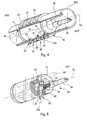
- a submerged underwater apparatus 1 according to the invention is used here to properly support and position a towed underwater object, in particular a towed linear acoustic antenna 3.
- the vehicle 1 comprises a hollow central body 5, and several wings rising around it, here three in number 7a, 7b, 7c ,.
- the body 5 has a longitudinal axis 5a corresponding to the axis of roll of the machine.
- This body comprises a fixed central portion 9 and an outer concentric shell 11 between which there is a possible relative rotation, about the axis 5a, of so that the wings can thus rotate around this axis, with the hull.
- the wings which extend along a transverse axis (here radial) to the axis 5a, are mounted individually pivotally about a pivot extending along their respective transverse axis of rotation, 13a, 13b, 13c.
- each wing is fixed towards its root, such as 17c for the wing 7c, to a pivot shaft (shaft 15c extending here radially, along the axis 13c, for the wing 7c).
- the radial shaft 15b passes through the outer shell 11 under which it is connected to a transverse leg 19 provided with a nipple or pin 21 which slides in the peripheral groove 23 of a ring 25 ( Figures 1 to 3).
- the ring 25 is traversed by two diametrically opposed holes 29 in each of which moves a finger 31 ( Figures 2 and 3).
- the finger 31 is an element of a radial eccentric device 33 driven by an angle gear 35 controlled by the output shaft 37 of an electric motor 39.
- the shaft 37 is controlled by a geared motor which rotates an axial screw 41 on which meshes the gear wheel with radial axis 43, thus defining the angle gear 35 ( Figure 5).
- the toothed wheel 43 is mounted on a radial shaft 45 which drives it in rotation.
- the shaft 45 is provided with an end eccentric, FIG.
- the assembly is identical for the wing 7a, with the ring 49 ( Figure 4).
- Two motors (see Figs.4,5: 39,39 ') and two actuator devices 29, 29', 31, 31 ', 37, 43, 39, 39' ... associated with the circular rings 25, 49, cause the wings 7a, 7b.
- the rotating rings 25, 49, and therefore the wings 7a, 7b, are shifted coaxially along the axis 5a.
- each wing can thus be adapted, either freely under the action of the outside and the ballast (wing 7c), or in a manner controlled by said motorized means (wings 7a, 7b ) here so called “actuators".
- actuators could be provided (cylinders ).
- the ballast 90 is mounted on the machine and located relative to the wing 7c, so that, the machine advancing along the roll axis 5a, a roll inclination of the wing will cause a couple tending to make pivoting this wing about its axis 13c, its leading edge 70c naturally oriented to cause an impact on the wing which will bring it back to said reference angular position of the machine thus corresponding to a reduced roll.
- the flange 7c will be located in a substantially vertical lower position and the two flanges 7a, 7b will be placed naturally in the upper position (above the body).
- the depth control will preferably be a local control using a pressure signal, as described in US-2005-0268835-A1 .
- the fixed central portion 9 of the body 5 is provided with first and second connection ends 53, 55.
- the free wing 7c is located under the body and the ballast 90,900, carried here by this wing, is located in front of the pivot 13c (see front end noted AVT).
- the lower wing 7c tends to rise and the mass of its ballast tends to prick.
- the wing takes a negative impact producing a downward force, thus reducing the roll.
- the weighted free wing 7c is always shown at the bottom, and the roll to starboard is due to the thrust of the high wings 7b, 7c, that the lower wing compensates only when the inclination is sufficient, as explained below.
- the ballast 90 requires the wing to plunge as soon as it is sufficiently removed from its reference angular position corresponding to a "zero roll", which rectifies the machine.
- the hydrodynamic thrust center CPD materialized at 117, is preferably located behind the pivot axis 13c, for this wing 7c (see sides before AVT and rear ARR).
- this wing 7c see sides before AVT and rear ARR.
- the hydrodynamic force is such that it produces a roll torque opposite the torque created by the other wings, here 7a, 7b. This force also creates a rotational torque on the wing.
- the weight is in turn located in front of the axis 13c and produces a torque of rotation of the wing on its axis, which, in equilibrium, is opposed to that of the hydrodynamic force.
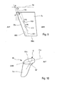
- FIG. 8 shows the line 111 for application of the hydrodynamic forces (thrust line) and locates at 113 the hydrodynamic thrust center (static, CPS).
- the center of thrust is situated on this line, at a position such that the surfaces on the root side and on the free end side of the wing are substantially equal.
- the equilibrium is reached when the torque of the weight is substantially equal to that of the hydrodynamic force, around the axis of the wing. The machine leans so until all these forces are balanced.
- the axis of rotation 13c is assumed vertical or at least perpendicular to the roll axis 5a.
- This inclination of the axis 13c by an angle other than 90 ° may allow the equilibrium angle of the wing at rest to be proportional to the heel of the craft and / or the damping by dynamic effect is even more effective.
- Tilting the axis 13c rearward and straightening the leading edge 70c of the wing can promote the damping of the oscillations when the machine produces lateral forces.
- Such inclination of the axis of rotation of the free wing may encourage placing the ballast at the wingtip, closer to its free end 700c, as fig.9 where the ballast is schematized 900 and is located just behind its leading edge.
- the free wing can be favorably made of composite material incorporating a foam.
- the buoyancy of the foam produces the same effect by buoyancy.
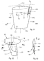
- Figures 10 to 19 show other possible embodiments, particularly in connection with the fact that the foregoing is applicable to a solution to rudder alone and / or wing provided with a rudder.
- the machine comprises only a wing 7c1 weighted at the front, for example 90 ', and mounted freely around its axis 13'c of pivoting relative to the central body 5' of the gear (roll axis 5'a). It may include some or all of the foregoing considerations.
- the body 5 'of the machine 10 may be monobloc.
- the ballast 910 is mounted on the wing 7c2, which pivots freely around its axis of rotation 13c2 which intersects the roll axis 5a which may be that of the body of the vehicle concerned, here not shown.
- the ballast 910 is mounted free of rotation about an axis 910a passing through the leading edges 911 and 913 of the wing.
- the ballast 910 is here placed towards the root of the wing, which carries a pivot shaft 13c2 axis.
- the ballast could be closer to the free end of the wing, or placed outside, for example beyond the wingtip.
- the wing carries the rudder 915 which is here pivotally mounted about an axis 915a parallel to the axis 13c2, along the trailing edge 913.
- the pivoting rudder 915 would advantageously be placed closer to the free end 700c.
- the ballast 920 and the rudder 915 are functionally interconnected by a control 917, such as a flexible cable or linkage, so that the pivoting of the ballast about its axis 910a, following a rolling action, acts on the 915 steering, or on the wing if it is itself pivotally mounted, to bring the machine to its reference angular position in roll and / or to participate in its orientation, when it advances (AVT) substantially parallel to the axis 5a, at a possible angle of skidding.
- a control 917 such as a flexible cable or linkage
- the ballast 920 has a direct effect on a rudder 921 pivotally mounted on and with respect to a wing 7c3 mounted on a machine body 50 with roll axis 5a.
- the wing 7c3 can be fixedly mounted on the body 50.
- wing 7c3 motorized steering wheel or fin 921 enslaved in roll by the ballast 920 operably linked to this rudder by the control 923.
- the command 923 can be one of those mentioned above.
- the ballast 920 is inside the body 50, to rotate freely along an angular sector, around the axis 920a parallel to the plane 925 containing the axis 5a and the yaw axis 5c, this characteristic being applicable to the case of Figures 11 or 14.
- FIGS. 14 and following show an indirect effect solution where a heel around the roll axis causes a rotation of rudder inducing a rotation, by variation of incidence, of the wing bearing this rudder and a reduction of the heel.
- the ballast 930 is placed in the body 51 of the machine 110.
- the ballast 930 which could be outside the body (likewise for the solution fig.12), pivots about an axis 930a parallel to 5a.
- a control of the aforementioned type, 931 transmits the effect of the ballast on the rear rudder 933.
- This rudder is pivotable relative to and behind the wing 7c4 which is free of rotation on and with respect to the body 51, about the axis 13c2 which intersects the roll axis 5a and passes through its root edges and free end.
- the axis 933a of the rudder 933 also intersects the axis 5a, but is not necessarily parallel to the axis 13c2.
- the pivoting shaft of the rudder along the axis 933a is carried by rods 935a, 935b fixed to the wing and extending behind its trailing edge 937.
- the wing 7c4 is here supposed to rotate freely about its axis 13c2, without being even subjected to the direct effect of any ballast.
- control 931 may comprise a cable, or for example a flexible rod 939 sliding in a sheath 941 and connecting on one side the control surface 933 (fig.14) and, on the other, by the intermediate of a pivot or ball 943, the ballast 930 which is pivotally mounted about its axis.
- the general equilibrium of the vehicle 110 is such that, if it advances substantially along the roll axis 5a of FIG. 14, it is naturally placed with the vertical free wing 7c4 and directed downward, directional force exerted.
- FIG. 16 shows what happens if the vehicle is lodged and that, consequently, the axis 13c2 of the wing 7c4 tilts with respect to the vertical: when the vehicle leans to port, the cable 939 is pulled . On the other hand, it is pushed if the gear is pitched to starboard, with the aforementioned effects.
- Figure 17 the machine advances in its position of Figure 15.
- the cable 939 and the wing 7c4 are in the neutral position.
- the wing and the rear rudder 933 can be oriented along the axis 5a of roll.
- an underwater vehicle equipped with a thruster such as a motor for driving at least one propeller, could be controlled at least partially by one of the ballast systems presented here. .
Landscapes
- Engineering & Computer Science (AREA)
- Mechanical Engineering (AREA)
- Aviation & Aerospace Engineering (AREA)
- Chemical & Material Sciences (AREA)
- Combustion & Propulsion (AREA)
- Ocean & Marine Engineering (AREA)
- Hydraulic Turbines (AREA)
- Other Liquid Machine Or Engine Such As Wave Power Use (AREA)
- Electric Cable Installation (AREA)
- Motor Or Generator Frames (AREA)
- Control Of Position, Course, Altitude, Or Attitude Of Moving Bodies (AREA)
- Measurement Of Velocity Or Position Using Acoustic Or Ultrasonic Waves (AREA)
- Automatic Cycles, And Cycles In General (AREA)
- Control Of Vehicle Engines Or Engines For Specific Uses (AREA)
- Laying Of Electric Cables Or Lines Outside (AREA)
- Output Control And Ontrol Of Special Type Engine (AREA)
- Current-Collector Devices For Electrically Propelled Vehicles (AREA)
- Vehicle Body Suspensions (AREA)
- Organic Low-Molecular-Weight Compounds And Preparation Thereof (AREA)
- Optical Communication System (AREA)
- Stereophonic System (AREA)
- Earth Drilling (AREA)
Applications Claiming Priority (1)
| Application Number | Priority Date | Filing Date | Title |
|---|---|---|---|
| FR0606453A FR2903655B1 (fr) | 2006-07-13 | 2006-07-13 | Dispositif de stabilisation dynamique d'un engin sous-marin. |
Publications (3)
| Publication Number | Publication Date |
|---|---|
| EP1897799A2 true EP1897799A2 (de) | 2008-03-12 |
| EP1897799A3 EP1897799A3 (de) | 2008-03-26 |
| EP1897799B1 EP1897799B1 (de) | 2010-03-24 |
Family
ID=37745157
Family Applications (1)
| Application Number | Title | Priority Date | Filing Date |
|---|---|---|---|
| EP07290867A Active EP1897799B1 (de) | 2006-07-13 | 2007-07-10 | Einrichtung für die dynamische Stabilisierung eines U-Bootes |
Country Status (7)
| Country | Link |
|---|---|
| US (1) | US7610871B2 (de) |
| EP (1) | EP1897799B1 (de) |
| CN (1) | CN101104438B (de) |
| AT (1) | ATE461860T1 (de) |
| DE (1) | DE602007005427D1 (de) |
| FR (1) | FR2903655B1 (de) |
| NO (1) | NO338013B1 (de) |
Families Citing this family (17)
| Publication number | Priority date | Publication date | Assignee | Title |
|---|---|---|---|---|
| FR2917063B1 (fr) | 2007-06-07 | 2009-12-04 | Cybernetix | Dispositif de fermeture d'un fuselage lie a un objet sous-marin remorque et engin ainsi equipe |
| GB0914314D0 (en) * | 2009-08-14 | 2009-09-30 | Ultra Electronics Ltd | Towable buoy |
| US9587645B2 (en) * | 2010-09-30 | 2017-03-07 | Pratt & Whitney Canada Corp. | Airfoil blade |
| US9254509B2 (en) | 2012-04-05 | 2016-02-09 | Cggveritas Services Sa | Active cleaning device for seismic streamers and related methods |
| FR3001302B1 (fr) | 2013-01-24 | 2016-01-22 | Cggveritas Services Sa | . |
| FR3003040B1 (fr) | 2013-03-05 | 2016-07-01 | Cggveritas Services Sa | Aile pliable pour un dispositif et procede de pilotage de flute |
| US9487282B2 (en) | 2014-04-08 | 2016-11-08 | Mrv Systems, Llc | Underwater vehicles configured to perform vertical profiling and diagonal profiling, and corresponding methods of operation |
| DK178119B1 (en) * | 2014-06-11 | 2015-06-01 | Seismisk Iq Bird Aps | SEISMIC EQUIPMENT POSITIONING APPLIANCES TOWED BY AN INQUIRY VESSEL |
| US9381987B1 (en) | 2015-10-01 | 2016-07-05 | Mrv Systems, Llc | Air-based-deployment-compatible underwater vehicle configured to perform vertical profiling and, during information transmission, perform motion stabilization at a water surface, and associated methods |
| CN105292416B (zh) * | 2015-11-05 | 2017-04-26 | 江苏科技大学 | 一种主动平衡耐压装备及其控制方法 |
| CN105460187B (zh) * | 2015-11-30 | 2017-12-08 | 天津大学 | 一种水下滑翔机变翼机构 |
| CN105539787B (zh) * | 2015-12-04 | 2017-09-29 | 天津大学 | 一种新型水下滑翔机翼型调整装置 |
| CN106275337B (zh) * | 2016-08-24 | 2018-01-19 | 合肥凌翔信息科技有限公司 | 一种可进行海底探测的仿生鱼 |
| US10718878B2 (en) | 2018-01-08 | 2020-07-21 | Cgg Services Sas | Method and system for hydrostatic balance control, based on pressure modelling, of a marine seismic vibrator |
| US20240166312A1 (en) * | 2022-11-23 | 2024-05-23 | Rabih Masri | Vehicle operable as an underwater glider and a surface sailing vehicle and a method thereof |
| FR3149095A1 (fr) | 2023-05-23 | 2024-11-29 | Sercel | Appareil de positionnement et système d’acquisition sismique correspondant |
| CN120080979B (zh) * | 2025-02-26 | 2025-11-28 | 中国船舶科学研究中心 | 专用于应急上浮的被动抗横倾装置及工作流程 |
Family Cites Families (13)
| Publication number | Priority date | Publication date | Assignee | Title |
|---|---|---|---|---|
| US2979010A (en) * | 1955-06-20 | 1961-04-11 | Sperry Rand Corp | Ship stabilization system |
| CA892351A (en) * | 1970-08-21 | 1972-02-08 | Dessureault Jean-Guy | Gravity controlled stabilizer |
| US3687100A (en) * | 1970-10-08 | 1972-08-29 | Everett P Larsh | Marine vessel roll stabilizer apparatus |
| US3934534A (en) * | 1972-07-19 | 1976-01-27 | Larsh Everett P | Marine vessel roll stabilizer apparatus |
| US3978813A (en) * | 1976-01-09 | 1976-09-07 | The United States Of America As Represented By The Secretary Of The Navy | Propeller-driven hydrophone array tensioning device |
| GB2025874B (en) * | 1978-06-19 | 1983-02-02 | Havre Chantiers | Ship stabilizer |
| JPS6274793A (ja) * | 1985-09-27 | 1987-04-06 | Hitachi Zosen Corp | 潜水式重金属回収装置 |
| US4686922A (en) * | 1986-06-27 | 1987-08-18 | Burroughs Ralph B | Swing wing keel |
| FR2744870B1 (fr) * | 1996-02-13 | 1998-03-06 | Thomson Csf | Procede pour controler la navigation d'une antenne acoustique lineaire remorquee, et dispositifs pour la mise en oeuvre d'un tel procede |
| DE19719306C2 (de) * | 1997-05-07 | 2000-05-18 | Stn Atlas Elektronik Gmbh | Schleppkörper |
| US6011752A (en) * | 1998-08-03 | 2000-01-04 | Western Atlas International, Inc. | Seismic streamer position control module |
| US6305309B1 (en) * | 2000-04-24 | 2001-10-23 | The United States Of America As Represented By The Secretary Of The Navy | Attitude and roll stabilizer for towed undersea devices |
| FR2870509B1 (fr) * | 2004-05-18 | 2007-08-17 | Cybernetix Sa | Dispositif de controle de la navigation d'un objet sous-marin remorque |
-
2006
- 2006-07-13 FR FR0606453A patent/FR2903655B1/fr not_active Expired - Fee Related
-
2007
- 2007-07-10 EP EP07290867A patent/EP1897799B1/de active Active
- 2007-07-10 AT AT07290867T patent/ATE461860T1/de not_active IP Right Cessation
- 2007-07-10 DE DE602007005427T patent/DE602007005427D1/de active Active
- 2007-07-11 CN CN200710130621.1A patent/CN101104438B/zh not_active Expired - Fee Related
- 2007-07-11 NO NO20073587A patent/NO338013B1/no unknown
- 2007-07-12 US US11/776,855 patent/US7610871B2/en active Active
Also Published As
| Publication number | Publication date |
|---|---|
| FR2903655B1 (fr) | 2009-04-17 |
| NO20073587L (no) | 2008-01-14 |
| EP1897799A3 (de) | 2008-03-26 |
| DE602007005427D1 (de) | 2010-05-06 |
| ATE461860T1 (de) | 2010-04-15 |
| CN101104438A (zh) | 2008-01-16 |
| FR2903655A1 (fr) | 2008-01-18 |
| US20080017094A1 (en) | 2008-01-24 |
| EP1897799B1 (de) | 2010-03-24 |
| US7610871B2 (en) | 2009-11-03 |
| CN101104438B (zh) | 2013-05-29 |
| NO338013B1 (no) | 2016-07-18 |
Similar Documents
| Publication | Publication Date | Title |
|---|---|---|
| EP1897799B1 (de) | Einrichtung für die dynamische Stabilisierung eines U-Bootes | |
| EP0385827A1 (de) | Antriebsvorrichtung für Unterseeboot | |
| EP3168126B1 (de) | Tragflügel in form eines umgedrehten t, der angepasst ist, um auf einem boot installiert zu werden | |
| EP3215416A1 (de) | Einziehbarer flügel | |
| EP3212498B1 (de) | Verbesserungen an drehmaschinen mit einem fluidrotor mit verstellbaren schaufeln | |
| EP0694008B1 (de) | Tragflügelboot mit segeln | |
| FR2887224A1 (fr) | Engin multimilieux | |
| WO2018229356A1 (fr) | Navire a plans porteurs a haute stabilite | |
| EP4363306B1 (de) | Aufrichtvorrichtung für ein unterwasserfahrzeug | |
| WO2018229355A1 (fr) | Navire a plans porteurs a haute stabilite | |
| EP0708017A1 (de) | Halbeintauchbare antriebseinheit für ein wasserfahrzeug | |
| WO2018229351A1 (fr) | Navire à plans porteurs à haute stabilité | |
| CA2359374C (fr) | Aerodyne a decollage et atterrissage verticaux | |
| FR2932772A1 (fr) | Embarcation multicoques rotatives. | |
| WO2018127631A1 (fr) | Mécanisme d'actionnement et de réglage quatre degrés de liberté d'un foil de bateau | |
| WO2018229354A1 (fr) | Navire a plans porteurs a haute stabilite | |
| WO2023094176A1 (fr) | Système de nageoires articulées pour bateau | |
| FR3125014A1 (fr) | Dispositif de direction a pivot vertical et appareil de propulsion de bateau comprenant celui-ci | |
| WO2025125765A1 (fr) | Dispositif de propulsion nautique et navire équipé du dispositif de propulsion | |
| FR2813060A1 (fr) | Dispositif de propulsion velique pour engins nautiques et terrestres | |
| FR2993238A1 (fr) | Structure navigante a traction par aile et montee sur foils | |
| WO1995013960A1 (fr) | Systeme de propulsion a voile pour embarcation | |
| HK1111389A (en) | Dynamic stabilisation device for a submarine vehicle | |
| WO2018229420A1 (fr) | Navire a plans porteurs a haute stabilite | |
| FR2797946A1 (fr) | Dispositif de montage d'un appendice rigide sur un engin apte a etre lance depuis le tube, et engin correspondant |
Legal Events
| Date | Code | Title | Description |
|---|---|---|---|
| PUAI | Public reference made under article 153(3) epc to a published international application that has entered the european phase |
Free format text: ORIGINAL CODE: 0009012 |
|
| PUAL | Search report despatched |
Free format text: ORIGINAL CODE: 0009013 |
|
| AK | Designated contracting states |
Kind code of ref document: A2 Designated state(s): AT BE BG CH CY CZ DE DK EE ES FI FR GB GR HU IE IS IT LI LT LU LV MC MT NL PL PT RO SE SI SK TR |
|
| AX | Request for extension of the european patent |
Extension state: AL BA HR MK YU |
|
| AK | Designated contracting states |
Kind code of ref document: A3 Designated state(s): AT BE BG CH CY CZ DE DK EE ES FI FR GB GR HU IE IS IT LI LT LU LV MC MT NL PL PT RO SE SI SK TR |
|
| AX | Request for extension of the european patent |
Extension state: AL BA HR MK YU |
|
| 17P | Request for examination filed |
Effective date: 20080926 |
|
| AKX | Designation fees paid |
Designated state(s): AT BE BG CH CY CZ DE DK EE ES FI FR GB GR HU IE IS IT LI LT LU LV MC MT NL PL PT RO SE SI SK TR |
|
| 17Q | First examination report despatched |
Effective date: 20081107 |
|
| GRAP | Despatch of communication of intention to grant a patent |
Free format text: ORIGINAL CODE: EPIDOSNIGR1 |
|
| GRAS | Grant fee paid |
Free format text: ORIGINAL CODE: EPIDOSNIGR3 |
|
| GRAA | (expected) grant |
Free format text: ORIGINAL CODE: 0009210 |
|
| AK | Designated contracting states |
Kind code of ref document: B1 Designated state(s): AT BE BG CH CY CZ DE DK EE ES FI FR GB GR HU IE IS IT LI LT LU LV MC MT NL PL PT RO SE SI SK TR |
|
| REG | Reference to a national code |
Ref country code: GB Ref legal event code: FG4D Free format text: NOT ENGLISH |
|
| REG | Reference to a national code |
Ref country code: CH Ref legal event code: EP |
|
| REG | Reference to a national code |
Ref country code: IE Ref legal event code: FG4D |
|
| REF | Corresponds to: |
Ref document number: 602007005427 Country of ref document: DE Date of ref document: 20100506 Kind code of ref document: P |
|
| REG | Reference to a national code |
Ref country code: NL Ref legal event code: T3 |
|
| PG25 | Lapsed in a contracting state [announced via postgrant information from national office to epo] |
Ref country code: LT Free format text: LAPSE BECAUSE OF FAILURE TO SUBMIT A TRANSLATION OF THE DESCRIPTION OR TO PAY THE FEE WITHIN THE PRESCRIBED TIME-LIMIT Effective date: 20100324 |
|
| LTIE | Lt: invalidation of european patent or patent extension |
Effective date: 20100324 |
|
| PG25 | Lapsed in a contracting state [announced via postgrant information from national office to epo] |
Ref country code: SI Free format text: LAPSE BECAUSE OF FAILURE TO SUBMIT A TRANSLATION OF THE DESCRIPTION OR TO PAY THE FEE WITHIN THE PRESCRIBED TIME-LIMIT Effective date: 20100324 Ref country code: PL Free format text: LAPSE BECAUSE OF FAILURE TO SUBMIT A TRANSLATION OF THE DESCRIPTION OR TO PAY THE FEE WITHIN THE PRESCRIBED TIME-LIMIT Effective date: 20100324 Ref country code: LV Free format text: LAPSE BECAUSE OF FAILURE TO SUBMIT A TRANSLATION OF THE DESCRIPTION OR TO PAY THE FEE WITHIN THE PRESCRIBED TIME-LIMIT Effective date: 20100324 Ref country code: FI Free format text: LAPSE BECAUSE OF FAILURE TO SUBMIT A TRANSLATION OF THE DESCRIPTION OR TO PAY THE FEE WITHIN THE PRESCRIBED TIME-LIMIT Effective date: 20100324 Ref country code: AT Free format text: LAPSE BECAUSE OF FAILURE TO SUBMIT A TRANSLATION OF THE DESCRIPTION OR TO PAY THE FEE WITHIN THE PRESCRIBED TIME-LIMIT Effective date: 20100324 |
|
| REG | Reference to a national code |
Ref country code: IE Ref legal event code: FD4D |
|
| PG25 | Lapsed in a contracting state [announced via postgrant information from national office to epo] |
Ref country code: SE Free format text: LAPSE BECAUSE OF FAILURE TO SUBMIT A TRANSLATION OF THE DESCRIPTION OR TO PAY THE FEE WITHIN THE PRESCRIBED TIME-LIMIT Effective date: 20100324 Ref country code: RO Free format text: LAPSE BECAUSE OF FAILURE TO SUBMIT A TRANSLATION OF THE DESCRIPTION OR TO PAY THE FEE WITHIN THE PRESCRIBED TIME-LIMIT Effective date: 20100324 Ref country code: GR Free format text: LAPSE BECAUSE OF FAILURE TO SUBMIT A TRANSLATION OF THE DESCRIPTION OR TO PAY THE FEE WITHIN THE PRESCRIBED TIME-LIMIT Effective date: 20100625 Ref country code: ES Free format text: LAPSE BECAUSE OF FAILURE TO SUBMIT A TRANSLATION OF THE DESCRIPTION OR TO PAY THE FEE WITHIN THE PRESCRIBED TIME-LIMIT Effective date: 20100705 Ref country code: EE Free format text: LAPSE BECAUSE OF FAILURE TO SUBMIT A TRANSLATION OF THE DESCRIPTION OR TO PAY THE FEE WITHIN THE PRESCRIBED TIME-LIMIT Effective date: 20100324 |
|
| PG25 | Lapsed in a contracting state [announced via postgrant information from national office to epo] |
Ref country code: SK Free format text: LAPSE BECAUSE OF FAILURE TO SUBMIT A TRANSLATION OF THE DESCRIPTION OR TO PAY THE FEE WITHIN THE PRESCRIBED TIME-LIMIT Effective date: 20100324 Ref country code: IS Free format text: LAPSE BECAUSE OF FAILURE TO SUBMIT A TRANSLATION OF THE DESCRIPTION OR TO PAY THE FEE WITHIN THE PRESCRIBED TIME-LIMIT Effective date: 20100724 Ref country code: CZ Free format text: LAPSE BECAUSE OF FAILURE TO SUBMIT A TRANSLATION OF THE DESCRIPTION OR TO PAY THE FEE WITHIN THE PRESCRIBED TIME-LIMIT Effective date: 20100324 Ref country code: BG Free format text: LAPSE BECAUSE OF FAILURE TO SUBMIT A TRANSLATION OF THE DESCRIPTION OR TO PAY THE FEE WITHIN THE PRESCRIBED TIME-LIMIT Effective date: 20100624 |
|
| PLBE | No opposition filed within time limit |
Free format text: ORIGINAL CODE: 0009261 |
|
| STAA | Information on the status of an ep patent application or granted ep patent |
Free format text: STATUS: NO OPPOSITION FILED WITHIN TIME LIMIT |
|
| BERE | Be: lapsed |
Owner name: SERCEL Effective date: 20100731 |
|
| PG25 | Lapsed in a contracting state [announced via postgrant information from national office to epo] |
Ref country code: PT Free format text: LAPSE BECAUSE OF FAILURE TO SUBMIT A TRANSLATION OF THE DESCRIPTION OR TO PAY THE FEE WITHIN THE PRESCRIBED TIME-LIMIT Effective date: 20100726 Ref country code: IE Free format text: LAPSE BECAUSE OF FAILURE TO SUBMIT A TRANSLATION OF THE DESCRIPTION OR TO PAY THE FEE WITHIN THE PRESCRIBED TIME-LIMIT Effective date: 20100324 Ref country code: DK Free format text: LAPSE BECAUSE OF FAILURE TO SUBMIT A TRANSLATION OF THE DESCRIPTION OR TO PAY THE FEE WITHIN THE PRESCRIBED TIME-LIMIT Effective date: 20100324 |
|
| PG25 | Lapsed in a contracting state [announced via postgrant information from national office to epo] |
Ref country code: MC Free format text: LAPSE BECAUSE OF NON-PAYMENT OF DUE FEES Effective date: 20100731 |
|
| 26N | No opposition filed |
Effective date: 20101228 |
|
| PG25 | Lapsed in a contracting state [announced via postgrant information from national office to epo] |
Ref country code: IT Free format text: LAPSE BECAUSE OF FAILURE TO SUBMIT A TRANSLATION OF THE DESCRIPTION OR TO PAY THE FEE WITHIN THE PRESCRIBED TIME-LIMIT Effective date: 20100324 |
|
| PG25 | Lapsed in a contracting state [announced via postgrant information from national office to epo] |
Ref country code: BE Free format text: LAPSE BECAUSE OF NON-PAYMENT OF DUE FEES Effective date: 20100731 |
|
| PG25 | Lapsed in a contracting state [announced via postgrant information from national office to epo] |
Ref country code: MT Free format text: LAPSE BECAUSE OF FAILURE TO SUBMIT A TRANSLATION OF THE DESCRIPTION OR TO PAY THE FEE WITHIN THE PRESCRIBED TIME-LIMIT Effective date: 20100324 |
|
| REG | Reference to a national code |
Ref country code: CH Ref legal event code: PL |
|
| PG25 | Lapsed in a contracting state [announced via postgrant information from national office to epo] |
Ref country code: LI Free format text: LAPSE BECAUSE OF NON-PAYMENT OF DUE FEES Effective date: 20110731 Ref country code: CH Free format text: LAPSE BECAUSE OF NON-PAYMENT OF DUE FEES Effective date: 20110731 |
|
| PG25 | Lapsed in a contracting state [announced via postgrant information from national office to epo] |
Ref country code: CY Free format text: LAPSE BECAUSE OF FAILURE TO SUBMIT A TRANSLATION OF THE DESCRIPTION OR TO PAY THE FEE WITHIN THE PRESCRIBED TIME-LIMIT Effective date: 20100324 |
|
| PG25 | Lapsed in a contracting state [announced via postgrant information from national office to epo] |
Ref country code: LU Free format text: LAPSE BECAUSE OF NON-PAYMENT OF DUE FEES Effective date: 20100710 Ref country code: HU Free format text: LAPSE BECAUSE OF FAILURE TO SUBMIT A TRANSLATION OF THE DESCRIPTION OR TO PAY THE FEE WITHIN THE PRESCRIBED TIME-LIMIT Effective date: 20100925 |
|
| PG25 | Lapsed in a contracting state [announced via postgrant information from national office to epo] |
Ref country code: TR Free format text: LAPSE BECAUSE OF FAILURE TO SUBMIT A TRANSLATION OF THE DESCRIPTION OR TO PAY THE FEE WITHIN THE PRESCRIBED TIME-LIMIT Effective date: 20100324 |
|
| REG | Reference to a national code |
Ref country code: FR Ref legal event code: PLFP Year of fee payment: 9 |
|
| REG | Reference to a national code |
Ref country code: FR Ref legal event code: PLFP Year of fee payment: 10 |
|
| REG | Reference to a national code |
Ref country code: FR Ref legal event code: PLFP Year of fee payment: 11 |
|
| REG | Reference to a national code |
Ref country code: FR Ref legal event code: PLFP Year of fee payment: 12 |
|
| PGFP | Annual fee paid to national office [announced via postgrant information from national office to epo] |
Ref country code: DE Payment date: 20190719 Year of fee payment: 13 |
|
| REG | Reference to a national code |
Ref country code: DE Ref legal event code: R119 Ref document number: 602007005427 Country of ref document: DE |
|
| PG25 | Lapsed in a contracting state [announced via postgrant information from national office to epo] |
Ref country code: DE Free format text: LAPSE BECAUSE OF NON-PAYMENT OF DUE FEES Effective date: 20210202 |
|
| PGFP | Annual fee paid to national office [announced via postgrant information from national office to epo] |
Ref country code: NL Payment date: 20230719 Year of fee payment: 17 |
|
| PGFP | Annual fee paid to national office [announced via postgrant information from national office to epo] |
Ref country code: FR Payment date: 20230725 Year of fee payment: 17 |
|
| REG | Reference to a national code |
Ref country code: NL Ref legal event code: MM Effective date: 20240801 |
|
| PG25 | Lapsed in a contracting state [announced via postgrant information from national office to epo] |
Ref country code: NL Free format text: LAPSE BECAUSE OF NON-PAYMENT OF DUE FEES Effective date: 20240801 |
|
| PG25 | Lapsed in a contracting state [announced via postgrant information from national office to epo] |
Ref country code: FR Free format text: LAPSE BECAUSE OF NON-PAYMENT OF DUE FEES Effective date: 20240731 |
|
| PGFP | Annual fee paid to national office [announced via postgrant information from national office to epo] |
Ref country code: GB Payment date: 20250722 Year of fee payment: 19 |