EP1898020A2 - Dispositif destiné à évacuer la fumée et la chaleur d'une pièce - Google Patents
Dispositif destiné à évacuer la fumée et la chaleur d'une pièce Download PDFInfo
- Publication number
- EP1898020A2 EP1898020A2 EP07015865A EP07015865A EP1898020A2 EP 1898020 A2 EP1898020 A2 EP 1898020A2 EP 07015865 A EP07015865 A EP 07015865A EP 07015865 A EP07015865 A EP 07015865A EP 1898020 A2 EP1898020 A2 EP 1898020A2
- Authority
- EP
- European Patent Office
- Prior art keywords
- flap
- frame
- smoke
- opening
- room
- Prior art date
- Legal status (The legal status is an assumption and is not a legal conclusion. Google has not performed a legal analysis and makes no representation as to the accuracy of the status listed.)
- Granted
Links
- 239000000779 smoke Substances 0.000 title claims 6
- 238000000605 extraction Methods 0.000 claims 2
- 238000009423 ventilation Methods 0.000 claims 2
- 238000013022 venting Methods 0.000 claims 1
- 230000000903 blocking effect Effects 0.000 abstract 1
Images


Classifications
-
- E—FIXED CONSTRUCTIONS
- E04—BUILDING
- E04D—ROOF COVERINGS; SKY-LIGHTS; GUTTERS; ROOF-WORKING TOOLS
- E04D13/00—Special arrangements or devices in connection with roof coverings; Protection against birds; Roof drainage ; Sky-lights
- E04D13/03—Sky-lights; Domes; Ventilating sky-lights
- E04D13/035—Sky-lights; Domes; Ventilating sky-lights characterised by having movable parts
- E04D13/0351—Sky-lights; Domes; Ventilating sky-lights characterised by having movable parts the parts pivoting about a fixed axis
- E04D13/0354—Sky-lights; Domes; Ventilating sky-lights characterised by having movable parts the parts pivoting about a fixed axis the parts being flat
-
- E—FIXED CONSTRUCTIONS
- E04—BUILDING
- E04D—ROOF COVERINGS; SKY-LIGHTS; GUTTERS; ROOF-WORKING TOOLS
- E04D13/00—Special arrangements or devices in connection with roof coverings; Protection against birds; Roof drainage ; Sky-lights
- E04D13/03—Sky-lights; Domes; Ventilating sky-lights
- E04D13/0305—Supports or connecting means for sky-lights of flat or domed shape
- E04D13/0315—Supports or connecting means for sky-lights of flat or domed shape characterised by a curb frame
-
- F—MECHANICAL ENGINEERING; LIGHTING; HEATING; WEAPONS; BLASTING
- F24—HEATING; RANGES; VENTILATING
- F24F—AIR-CONDITIONING; AIR-HUMIDIFICATION; VENTILATION; USE OF AIR CURRENTS FOR SCREENING
- F24F7/00—Ventilation
- F24F7/02—Roof ventilation
-
- E—FIXED CONSTRUCTIONS
- E05—LOCKS; KEYS; WINDOW OR DOOR FITTINGS; SAFES
- E05D—HINGES OR SUSPENSION DEVICES FOR DOORS, WINDOWS OR WINGS
- E05D3/00—Hinges with pins
- E05D3/06—Hinges with pins with two or more pins
- E05D3/12—Hinges with pins with two or more pins with two parallel pins and one arm
-
- E—FIXED CONSTRUCTIONS
- E05—LOCKS; KEYS; WINDOW OR DOOR FITTINGS; SAFES
- E05Y—INDEXING SCHEME ASSOCIATED WITH SUBCLASSES E05D AND E05F, RELATING TO CONSTRUCTION ELEMENTS, ELECTRIC CONTROL, POWER SUPPLY, POWER SIGNAL OR TRANSMISSION, USER INTERFACES, MOUNTING OR COUPLING, DETAILS, ACCESSORIES, AUXILIARY OPERATIONS NOT OTHERWISE PROVIDED FOR, APPLICATION THEREOF
- E05Y2900/00—Application of doors, windows, wings or fittings thereof
- E05Y2900/10—Application of doors, windows, wings or fittings thereof for buildings or parts thereof
- E05Y2900/13—Type of wing
- E05Y2900/148—Windows
- E05Y2900/152—Roof windows
Definitions
- the present invention relates to a device for smoke and heat exhaust ventilation and for ventilation of rooms.
- Such devices are also known, for example, as light elements with a frame surrounding a roof opening on which a hinge is pivotally mounted by means of a hinge and is arranged lockable on the opposite side of the frame.
- the opening of the flap by means of lifting element to the outside.
- Such light elements may e.g. Skylight domes or roof skylight integrated light flaps, which are installed in openings of flat or slightly inclined roofs.
- Such flaps generally serve the required and mandatory smoke and heat extraction, especially in case of disaster, in which they are opened by remote release either with an automatic thermal release or manually by means of a lifting element.
- U1 From the DE 297 06 030 U1 is a smoke and heat exhaust system is known, which has a ventilation opening at the top of a staircase.
- the ventilation opening is closed by means of a hinged flap.
- opening means serves a rack motor whose rack opens the flap to the outside. Smoke or warm air can escape from the stairwell into the environment via the open flap.
- the cited smoke and heat exhaust systems called RWA can lose their functionality in certain weather conditions. If, as in the winter of 2005/2006, the snow masses on the roofs of buildings are unusually high, the RWAs are covered by the snow. The mechanical opening devices are no longer able to move the upwardly and outwardly opening flaps against the snow load. In the event of a fire, this means that the RWA can no longer discharge the smoke and heat to the outside due to the lack of opening possibilities. A smoke of the rooms, or the building is the result and a rescue or a controlled fire attack are no longer possible. In addition, due to the lack of heat dissipation, the temperature in the burning building increases faster than was considered in the design of the building, so that adverse effects on the static of the structures are unavoidable and can lead to failure of the structures.
- the known RWA can therefore no longer ensure their function in certain weather conditions, so that In these cases, high personal injury and property damage may result.
- the present invention is therefore based on the object to provide a device for ventilation of rooms, which does not have the disadvantages of the prior art, and ensures the withdrawal of smoke and heat even at high snow loads on their installation locations ,
- the advantages of the device according to the invention are in the high reliability and in the prevention or at least reduce high personal injury and property damage in case of fire.
- a device for smoke and heat exhaust ventilation and ventilation of rooms in which a flap, is mounted on a roof opening bounding a frame such that the roof opening with the help of the flap to open and close, the frame and the flap are formed so that at least one opening of the flap is possible inwardly towards the room, wherein it is particularly advantageous if the flap is parallel to the frame inwardly to open towards the room.
- an apparatus for smoke and heat extraction and for ventilation of rooms is advantageous if a flap is pivotally mounted on a roof opening bounding a frame by means of at least one hinge and lockable on the hinge opposite side, and if the hinge is designed so that it at least opening the flap inward towards the room.
- the flap is surrounded by an at least two-part frame in such a manner, wherein a main frame and an auxiliary frame is formed, so that the flap can be opened by means of the auxiliary frame inwardly toward the room.
- the flap is framed by an at least two-part frame such that a main frame and an auxiliary frame is formed, and when the flap by means of the main frame to the outside and / or by means of the auxiliary Frame opens inward towards the room.
- auxiliary frame is an integral part of the flap.
- a device of the type mentioned is particularly advantageous when the locking and unlocking of the flap takes place by means of temperature-sensitive element.
- a flap if it has a translucent disc or a translucent dome.
- a device is also advantageous if the flap is an integral part of a light band.
- the flap can also be an integrated component of a multi-flap smoke extraction device or an integrated component of a light and / or smoke dome.
- a device is particularly advantageous when the auxiliary frame is an integral part of a light and / or smoke dome.
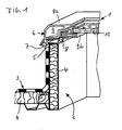
- a smoke and heat exhaust system 1 shown schematically in Figure 1 is located in an opening 2 of a roof 3.
- the roof 3 is provided with an insulation 4, which is also in the interior of the opening 2 of the roof 3.
- the opening 2 in the roof 3 is bounded by a frame 5.
- a flap 6 of the smoke and heat suit 1 is attached to a not shown and therefore not designated hinge hinged.
- the flap 6 of the smoke and heat exhaust system 1 is located on the frame 5.
- sealing elements 7 and 8 are provided, which are located between the frame 5 and a frame 9 which surrounds the flap 6 and corresponds to the frame 5.
- the frame 9 is formed in two parts and consists of a main frame 9a and an auxiliary frame 9b.
- the auxiliary frame 9b receives a disk 10, through which light into the opening 2 of the roof 3 passes.
- the main frame 9a receives the auxiliary frame 9b together with the disk 10.
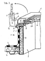
- FIG. 3 shows the special situation in the special emergency.
- a snow load S is stored on the smoke and heat exhaust system 1 and in its environment and prevents it from opening to the outside.
- the conventional solutions do not allow an opening to the outside, since the movement space of the smoke and heat exhaust system 1 is blocked by snow and ice masses S.
- the flap 6 is already opened in accordance with the invention inside and the snow load S is already slid inward in the region of the released opening, so that the area is shown above the opening 2 without snow load.
- the function of the conventional smoke and heat exhaust systems 1 based on the fact that correspondingly large opening areas in the described type of skylights or other mechanically outwardly opening smoke and heat exhaust flaps by means of control and movement elements moves up and be opened to the outside. The warm or hot smoke and fire gases are thereby discharged into the open air.
- the flaps In the case of larger amounts of snow S on the roof 3 of the building, the flaps must raise and displace overlapping snow masses during the opening process. A small portion of the snow masses will slip off the smoke and heat extraction system through the opening process and fall through the resulting opening into the interior of the room. The larger proportion is compressed at corresponding snow masses during the unfolding process and block the further opening of the smoke and heat exhaust system. It should also be taken into account that the forces to be applied for opening rise sharply, since the transition edges around the opening have ice layers which additionally have to be broken up. The function of the smoke and heat exhaust system is therefore no longer guaranteed when resting large amounts of snow.
- the snow and ice masses support by their own weight, the tendency of the flap 6, to open down.
- various locking and unlocking mechanisms offer.
- a known per se thermal locking and unlocking can be provided.
- additional opening energy may not be required.
- pneumatic, hydraulic, mechanical and / or electromechanical devices Such a solution always ensures a reliable opening to the inside when a predetermined temperature is reached in the room.
- the triggering of the opening can also be done via a known per se smoke detectors or other triggering elements.
- retaining elements ensures that the flap 6 when opening can not fall down into the room. This measure prevents additional injury hazards.
- retaining elements are not the subject of the invention, they may be formed as chains, telescopic rods or the like.
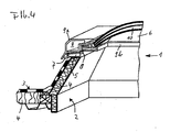
- FIG. 4 shows a further exemplary embodiment in the form of a dome light.
- a smoke and heat exhaust system 1 covers an opening 2 in a roof 3, which is provided with an insulation 4.
- a frame 5 encloses the opening 2 at its upper periphery.
- On the frame 5 is a frame 9 a flap 6, which is open and serves as a smoke and heat exhaust.
- the frame 9 carries a translucent dome 10, which allows an exposure of the room.
- the dome 10 is open by means of the frame 9. It consists of the frame 9 - as in the previous embodiment - consists of two parts, the main frame 9a and the auxiliary frame 9b.
- the flap 6 is moved with the dome 10 by means of the entire frame 9 upwards.
- Serve opening mechanisms as they are well known from the prior art. This is not shown here for this reason and need not be explained in detail.
- the frame 9 is formed in two parts and consists essentially of a main frame 9a and a subframe 9b. With the help of the main frame 9a, the flap 6 can be opened to the outside and with the help of the subframe 9b, the flap 6 can be opened inwards towards the room, which is advantageous in the event of a disaster. Due to a high snow load S, the flap 6 with the dome 10 can not be opened to the outside in case of disaster. However, the two-part frame 9 still allows the maintenance of the smoke and heat dissipating function of the smoke and heat exhaust system by the flap 6 with the dome 10 by means of the subframe 9b can be opened inwardly towards the room.
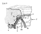
- FIG. 6 shows a smoke and heat exhaust system 1, in which the auxiliary frame 9b is an integral part of the flap 6 in a particularly advantageous manner.
- This embodiment can provide manufacturing advantages.
- the other components correspond mutatis mutandis to the examples described above and are shown as highly schematic in all drawings.
Landscapes
- Engineering & Computer Science (AREA)
- Architecture (AREA)
- Civil Engineering (AREA)
- Structural Engineering (AREA)
- Mechanical Engineering (AREA)
- Combustion & Propulsion (AREA)
- Chemical & Material Sciences (AREA)
- General Engineering & Computer Science (AREA)
- Building Environments (AREA)
- Power-Operated Mechanisms For Wings (AREA)
- Door And Window Frames Mounted To Openings (AREA)
- Roof Covering Using Slabs Or Stiff Sheets (AREA)
- Specific Sealing Or Ventilating Devices For Doors And Windows (AREA)
Applications Claiming Priority (1)
| Application Number | Priority Date | Filing Date | Title |
|---|---|---|---|
| DE102006038009A DE102006038009B4 (de) | 2006-08-14 | 2006-08-14 | Vorrichtung zum Rauch- und Wärmeabzug von Räumen |
Publications (3)
| Publication Number | Publication Date |
|---|---|
| EP1898020A2 true EP1898020A2 (fr) | 2008-03-12 |
| EP1898020A3 EP1898020A3 (fr) | 2010-06-02 |
| EP1898020B1 EP1898020B1 (fr) | 2011-10-19 |
Family
ID=38954721
Family Applications (1)
| Application Number | Title | Priority Date | Filing Date |
|---|---|---|---|
| EP07015865A Not-in-force EP1898020B1 (fr) | 2006-08-14 | 2007-08-13 | Dispositif destiné à évacuer la fumée et la chaleur d'une pièce |
Country Status (3)
| Country | Link |
|---|---|
| EP (1) | EP1898020B1 (fr) |
| AT (1) | ATE529585T1 (fr) |
| DE (1) | DE102006038009B4 (fr) |
Citations (5)
| Publication number | Priority date | Publication date | Assignee | Title |
|---|---|---|---|---|
| DE2516098A1 (de) | 1974-04-23 | 1975-11-13 | Svenska Icopalfabriken Ab | Entlueftungseinrichtung, insbesondere rauch- und brandentlueftungseinrichtung |
| DE3345185A1 (de) | 1983-12-14 | 1985-06-27 | Resopal Werk H. Römmler GmbH, 6800 Mannheim | Dachflaechenfenster |
| DE3338092C2 (fr) | 1983-10-20 | 1994-08-04 | Fa. J. Eberspaecher, 7300 Esslingen, De | |
| DE9411812U1 (de) | 1994-07-21 | 1994-09-15 | E.M.B. Metallbau und Brandschutztechnik GmbH, 46446 Emmerich | Doppelklappenlüfter als Klappenanordnung im Firstbereich eines Daches oder eines Satteloberlichtbandes |
| DE29706030U1 (de) | 1997-01-08 | 1997-08-21 | Engelhardt, Walter, 39179 Ebendorf | Rauch- und Wärmeabzugsanlage |
Family Cites Families (9)
| Publication number | Priority date | Publication date | Assignee | Title |
|---|---|---|---|---|
| DE2634565A1 (de) * | 1976-07-31 | 1978-02-02 | Iva Ingenieurgesellschaft Mbh | Einrichtung zum oeffnen einer kombinierten lueftungs-rauch- und waermeabzugsklappe |
| DE2914475A1 (de) * | 1979-04-10 | 1980-10-30 | Eberspaecher J | Einrichtung zur entlueftung und zum rauch- und waermeabzug an gebaeuden |
| FR2481353A1 (fr) * | 1980-04-29 | 1981-10-30 | Yves Fourtane | Bloc de fixation d'un vantail de porte va-et-vient |
| JPS5761168A (en) * | 1980-09-30 | 1982-04-13 | Nippon Air Brake Co | Skylight operator |
| DD223491A1 (de) * | 1984-04-13 | 1985-06-12 | Berlin Baumechanisierung | Universaler einsatzfluegel fuer erdgeschoss- und grossverglasungen |
| US4663905A (en) * | 1986-09-02 | 1987-05-12 | Kenneth Schulz | Skylight assembly |
| DE19534614A1 (de) * | 1995-09-18 | 1997-03-20 | Winkhaus Fa August | Sicherheitssperreinrichtung für eine Betätigungsvorrichtung zum Öffnen und Schließen eines Flügels eines Fensters, einer Tür, einer Lüftungsklappe oder dergleichen |
| DE102004016458B3 (de) * | 2004-03-31 | 2005-03-03 | Wolfgang Stief | Antriebsvorrichtung für einen Öffnungsmechanismus zum Betätigen von Türen, Fenstern oder dergleichen |
| DE202005012111U1 (de) * | 2005-08-02 | 2005-12-15 | PARAT Automotive Schönenbach GmbH + Co. KG | Blendrahmen |
-
2006
- 2006-08-14 DE DE102006038009A patent/DE102006038009B4/de not_active Expired - Fee Related
-
2007
- 2007-08-13 EP EP07015865A patent/EP1898020B1/fr not_active Not-in-force
- 2007-08-13 AT AT07015865T patent/ATE529585T1/de active
Patent Citations (5)
| Publication number | Priority date | Publication date | Assignee | Title |
|---|---|---|---|---|
| DE2516098A1 (de) | 1974-04-23 | 1975-11-13 | Svenska Icopalfabriken Ab | Entlueftungseinrichtung, insbesondere rauch- und brandentlueftungseinrichtung |
| DE3338092C2 (fr) | 1983-10-20 | 1994-08-04 | Fa. J. Eberspaecher, 7300 Esslingen, De | |
| DE3345185A1 (de) | 1983-12-14 | 1985-06-27 | Resopal Werk H. Römmler GmbH, 6800 Mannheim | Dachflaechenfenster |
| DE9411812U1 (de) | 1994-07-21 | 1994-09-15 | E.M.B. Metallbau und Brandschutztechnik GmbH, 46446 Emmerich | Doppelklappenlüfter als Klappenanordnung im Firstbereich eines Daches oder eines Satteloberlichtbandes |
| DE29706030U1 (de) | 1997-01-08 | 1997-08-21 | Engelhardt, Walter, 39179 Ebendorf | Rauch- und Wärmeabzugsanlage |
Also Published As
| Publication number | Publication date |
|---|---|
| EP1898020A3 (fr) | 2010-06-02 |
| EP1898020B1 (fr) | 2011-10-19 |
| DE102006038009B4 (de) | 2011-04-28 |
| ATE529585T1 (de) | 2011-11-15 |
| DE102006038009A1 (de) | 2008-02-21 |
Similar Documents
| Publication | Publication Date | Title |
|---|---|---|
| DE2239438C3 (de) | Zweischaliges Fassadenelement für Gebäude | |
| DE102014115452B4 (de) | Verschlussanordnung an einer Lüftungsöffnung in einer Decke eines Aufzugsschachtes | |
| EP1703066A2 (fr) | Porte coupe-feu et coupe-fumée | |
| EP3643849B1 (fr) | Ouverture de toit, de plafond ou de façade | |
| DE102007010261B4 (de) | Vorrichtung zum selbsttätigen Schließen eines Fensterkippflügels zum Schutz vor eindringendem Wasser | |
| DE9409176U1 (de) | Rauchschutzeinrichtung für einen geschlossenen Treppenraum | |
| EP1898020B1 (fr) | Dispositif destiné à évacuer la fumée et la chaleur d'une pièce | |
| AT521543B1 (de) | Schutzvorrichtung für Roll- und Sektionaltore | |
| EP3853425B1 (fr) | Bâtiment à plusieurs étages comprenant des issues d'accès et de secours sûres en cas d'incendie | |
| DE202006012471U1 (de) | Vorrichtung zu Rauch- und Wärmeabzug von Räumen | |
| EP4423341A1 (fr) | Tunnel en feuilles pour voies de circulation | |
| DE202020003790U1 (de) | Dachfensteranordnung | |
| EP4237649B1 (fr) | Fermeture dotée d'un dispositif de clapet | |
| EP0656451A1 (fr) | Dispositif d'aération pour toits d'édifices | |
| DE29821814U1 (de) | Rauchabzug mit Insektenschutz | |
| AT522398B1 (de) | Klappschott | |
| DE202012100137U1 (de) | Satteldachkonstruktion | |
| EP3587696B1 (fr) | Dispositif de fermeture d'espace pouvant être ouvert ainsi que son procédé d'ouverture | |
| DE2458497A1 (de) | Schalt- oder umspannstation | |
| DE29614941U1 (de) | Brandschutzeinrichtung für eine Lüftungsrohrleitung | |
| DE2438547A1 (de) | Anordnung zum oeffnen von rauch- und waermeabzugseinrichtungen | |
| DE2150453A1 (de) | Arbeitsbuehne zum durchfuehren von arbeiten an hochbauten | |
| DE102005040824B4 (de) | Dachgaupe | |
| DE202009012206U1 (de) | Dach für eine Konstruktion im Innenbereich eines Gebäudes | |
| DE2612453A1 (de) | Rauch- und waermeabzugshaube |
Legal Events
| Date | Code | Title | Description |
|---|---|---|---|
| PUAI | Public reference made under article 153(3) epc to a published international application that has entered the european phase |
Free format text: ORIGINAL CODE: 0009012 |
|
| AK | Designated contracting states |
Kind code of ref document: A2 Designated state(s): AT BE BG CH CY CZ DE DK EE ES FI FR GB GR HU IE IS IT LI LT LU LV MC MT NL PL PT RO SE SI SK TR |
|
| AX | Request for extension of the european patent |
Extension state: AL BA HR MK YU |
|
| PUAL | Search report despatched |
Free format text: ORIGINAL CODE: 0009013 |
|
| AK | Designated contracting states |
Kind code of ref document: A3 Designated state(s): AT BE BG CH CY CZ DE DK EE ES FI FR GB GR HU IE IS IT LI LT LU LV MC MT NL PL PT RO SE SI SK TR |
|
| AX | Request for extension of the european patent |
Extension state: AL BA HR MK RS |
|
| 17P | Request for examination filed |
Effective date: 20101129 |
|
| AKX | Designation fees paid |
Designated state(s): AT BE BG CH CY CZ DE DK EE ES FI FR GB GR HU IE IS IT LI LT LU LV MC MT NL PL PT RO SE SI SK TR |
|
| GRAP | Despatch of communication of intention to grant a patent |
Free format text: ORIGINAL CODE: EPIDOSNIGR1 |
|
| RIC1 | Information provided on ipc code assigned before grant |
Ipc: E04D 13/03 20060101AFI20110315BHEP Ipc: F24F 7/02 20060101ALI20110315BHEP |
|
| GRAS | Grant fee paid |
Free format text: ORIGINAL CODE: EPIDOSNIGR3 |
|
| GRAA | (expected) grant |
Free format text: ORIGINAL CODE: 0009210 |
|
| AK | Designated contracting states |
Kind code of ref document: B1 Designated state(s): AT BE BG CH CY CZ DE DK EE ES FI FR GB GR HU IE IS IT LI LT LU LV MC MT NL PL PT RO SE SI SK TR |
|
| REG | Reference to a national code |
Ref country code: GB Ref legal event code: FG4D Free format text: NOT ENGLISH |
|
| REG | Reference to a national code |
Ref country code: CH Ref legal event code: EP |
|
| REG | Reference to a national code |
Ref country code: IE Ref legal event code: FG4D |
|
| REG | Reference to a national code |
Ref country code: DE Ref legal event code: R096 Ref document number: 502007008406 Country of ref document: DE Effective date: 20111215 |
|
| REG | Reference to a national code |
Ref country code: NL Ref legal event code: VDEP Effective date: 20111019 |
|
| LTIE | Lt: invalidation of european patent or patent extension |
Effective date: 20111019 |
|
| PG25 | Lapsed in a contracting state [announced via postgrant information from national office to epo] |
Ref country code: LT Free format text: LAPSE BECAUSE OF FAILURE TO SUBMIT A TRANSLATION OF THE DESCRIPTION OR TO PAY THE FEE WITHIN THE PRESCRIBED TIME-LIMIT Effective date: 20111019 Ref country code: IS Free format text: LAPSE BECAUSE OF FAILURE TO SUBMIT A TRANSLATION OF THE DESCRIPTION OR TO PAY THE FEE WITHIN THE PRESCRIBED TIME-LIMIT Effective date: 20120219 |
|
| REG | Reference to a national code |
Ref country code: IE Ref legal event code: FD4D |
|
| PG25 | Lapsed in a contracting state [announced via postgrant information from national office to epo] |
Ref country code: LV Free format text: LAPSE BECAUSE OF FAILURE TO SUBMIT A TRANSLATION OF THE DESCRIPTION OR TO PAY THE FEE WITHIN THE PRESCRIBED TIME-LIMIT Effective date: 20111019 Ref country code: SI Free format text: LAPSE BECAUSE OF FAILURE TO SUBMIT A TRANSLATION OF THE DESCRIPTION OR TO PAY THE FEE WITHIN THE PRESCRIBED TIME-LIMIT Effective date: 20111019 Ref country code: GR Free format text: LAPSE BECAUSE OF FAILURE TO SUBMIT A TRANSLATION OF THE DESCRIPTION OR TO PAY THE FEE WITHIN THE PRESCRIBED TIME-LIMIT Effective date: 20120120 Ref country code: SE Free format text: LAPSE BECAUSE OF FAILURE TO SUBMIT A TRANSLATION OF THE DESCRIPTION OR TO PAY THE FEE WITHIN THE PRESCRIBED TIME-LIMIT Effective date: 20111019 Ref country code: PT Free format text: LAPSE BECAUSE OF FAILURE TO SUBMIT A TRANSLATION OF THE DESCRIPTION OR TO PAY THE FEE WITHIN THE PRESCRIBED TIME-LIMIT Effective date: 20120220 Ref country code: NL Free format text: LAPSE BECAUSE OF FAILURE TO SUBMIT A TRANSLATION OF THE DESCRIPTION OR TO PAY THE FEE WITHIN THE PRESCRIBED TIME-LIMIT Effective date: 20111019 |
|
| PG25 | Lapsed in a contracting state [announced via postgrant information from national office to epo] |
Ref country code: CY Free format text: LAPSE BECAUSE OF FAILURE TO SUBMIT A TRANSLATION OF THE DESCRIPTION OR TO PAY THE FEE WITHIN THE PRESCRIBED TIME-LIMIT Effective date: 20111019 |
|
| PG25 | Lapsed in a contracting state [announced via postgrant information from national office to epo] |
Ref country code: DK Free format text: LAPSE BECAUSE OF FAILURE TO SUBMIT A TRANSLATION OF THE DESCRIPTION OR TO PAY THE FEE WITHIN THE PRESCRIBED TIME-LIMIT Effective date: 20111019 Ref country code: CZ Free format text: LAPSE BECAUSE OF FAILURE TO SUBMIT A TRANSLATION OF THE DESCRIPTION OR TO PAY THE FEE WITHIN THE PRESCRIBED TIME-LIMIT Effective date: 20111019 Ref country code: BG Free format text: LAPSE BECAUSE OF FAILURE TO SUBMIT A TRANSLATION OF THE DESCRIPTION OR TO PAY THE FEE WITHIN THE PRESCRIBED TIME-LIMIT Effective date: 20120119 Ref country code: IE Free format text: LAPSE BECAUSE OF FAILURE TO SUBMIT A TRANSLATION OF THE DESCRIPTION OR TO PAY THE FEE WITHIN THE PRESCRIBED TIME-LIMIT Effective date: 20111019 Ref country code: EE Free format text: LAPSE BECAUSE OF FAILURE TO SUBMIT A TRANSLATION OF THE DESCRIPTION OR TO PAY THE FEE WITHIN THE PRESCRIBED TIME-LIMIT Effective date: 20111019 Ref country code: SK Free format text: LAPSE BECAUSE OF FAILURE TO SUBMIT A TRANSLATION OF THE DESCRIPTION OR TO PAY THE FEE WITHIN THE PRESCRIBED TIME-LIMIT Effective date: 20111019 |
|
| PLBE | No opposition filed within time limit |
Free format text: ORIGINAL CODE: 0009261 |
|
| STAA | Information on the status of an ep patent application or granted ep patent |
Free format text: STATUS: NO OPPOSITION FILED WITHIN TIME LIMIT |
|
| PG25 | Lapsed in a contracting state [announced via postgrant information from national office to epo] |
Ref country code: RO Free format text: LAPSE BECAUSE OF FAILURE TO SUBMIT A TRANSLATION OF THE DESCRIPTION OR TO PAY THE FEE WITHIN THE PRESCRIBED TIME-LIMIT Effective date: 20111019 Ref country code: IT Free format text: LAPSE BECAUSE OF FAILURE TO SUBMIT A TRANSLATION OF THE DESCRIPTION OR TO PAY THE FEE WITHIN THE PRESCRIBED TIME-LIMIT Effective date: 20111019 Ref country code: PL Free format text: LAPSE BECAUSE OF FAILURE TO SUBMIT A TRANSLATION OF THE DESCRIPTION OR TO PAY THE FEE WITHIN THE PRESCRIBED TIME-LIMIT Effective date: 20111019 |
|
| 26N | No opposition filed |
Effective date: 20120720 |
|
| REG | Reference to a national code |
Ref country code: DE Ref legal event code: R097 Ref document number: 502007008406 Country of ref document: DE Effective date: 20120720 |
|
| BERE | Be: lapsed |
Owner name: HEWENER, HERMANN Effective date: 20120831 |
|
| REG | Reference to a national code |
Ref country code: CH Ref legal event code: PL |
|
| PG25 | Lapsed in a contracting state [announced via postgrant information from national office to epo] |
Ref country code: MC Free format text: LAPSE BECAUSE OF NON-PAYMENT OF DUE FEES Effective date: 20120831 |
|
| GBPC | Gb: european patent ceased through non-payment of renewal fee |
Effective date: 20120813 |
|
| PG25 | Lapsed in a contracting state [announced via postgrant information from national office to epo] |
Ref country code: CH Free format text: LAPSE BECAUSE OF NON-PAYMENT OF DUE FEES Effective date: 20120831 Ref country code: LI Free format text: LAPSE BECAUSE OF NON-PAYMENT OF DUE FEES Effective date: 20120831 |
|
| REG | Reference to a national code |
Ref country code: FR Ref legal event code: ST Effective date: 20130430 |
|
| PG25 | Lapsed in a contracting state [announced via postgrant information from national office to epo] |
Ref country code: BE Free format text: LAPSE BECAUSE OF NON-PAYMENT OF DUE FEES Effective date: 20120831 |
|
| PG25 | Lapsed in a contracting state [announced via postgrant information from national office to epo] |
Ref country code: FI Free format text: LAPSE BECAUSE OF FAILURE TO SUBMIT A TRANSLATION OF THE DESCRIPTION OR TO PAY THE FEE WITHIN THE PRESCRIBED TIME-LIMIT Effective date: 20111019 |
|
| PG25 | Lapsed in a contracting state [announced via postgrant information from national office to epo] |
Ref country code: GB Free format text: LAPSE BECAUSE OF NON-PAYMENT OF DUE FEES Effective date: 20120813 Ref country code: DE Free format text: LAPSE BECAUSE OF NON-PAYMENT OF DUE FEES Effective date: 20130301 |
|
| PG25 | Lapsed in a contracting state [announced via postgrant information from national office to epo] |
Ref country code: FR Free format text: LAPSE BECAUSE OF NON-PAYMENT OF DUE FEES Effective date: 20120831 |
|
| REG | Reference to a national code |
Ref country code: DE Ref legal event code: R119 Ref document number: 502007008406 Country of ref document: DE Effective date: 20130301 |
|
| REG | Reference to a national code |
Ref country code: AT Ref legal event code: MM01 Ref document number: 529585 Country of ref document: AT Kind code of ref document: T Effective date: 20120831 |
|
| PG25 | Lapsed in a contracting state [announced via postgrant information from national office to epo] |
Ref country code: AT Free format text: LAPSE BECAUSE OF NON-PAYMENT OF DUE FEES Effective date: 20120831 Ref country code: ES Free format text: LAPSE BECAUSE OF FAILURE TO SUBMIT A TRANSLATION OF THE DESCRIPTION OR TO PAY THE FEE WITHIN THE PRESCRIBED TIME-LIMIT Effective date: 20120130 |
|
| PG25 | Lapsed in a contracting state [announced via postgrant information from national office to epo] |
Ref country code: MT Free format text: LAPSE BECAUSE OF FAILURE TO SUBMIT A TRANSLATION OF THE DESCRIPTION OR TO PAY THE FEE WITHIN THE PRESCRIBED TIME-LIMIT Effective date: 20111019 |
|
| PG25 | Lapsed in a contracting state [announced via postgrant information from national office to epo] |
Ref country code: TR Free format text: LAPSE BECAUSE OF FAILURE TO SUBMIT A TRANSLATION OF THE DESCRIPTION OR TO PAY THE FEE WITHIN THE PRESCRIBED TIME-LIMIT Effective date: 20111019 |
|
| PG25 | Lapsed in a contracting state [announced via postgrant information from national office to epo] |
Ref country code: LU Free format text: LAPSE BECAUSE OF NON-PAYMENT OF DUE FEES Effective date: 20120813 |
|
| PG25 | Lapsed in a contracting state [announced via postgrant information from national office to epo] |
Ref country code: HU Free format text: LAPSE BECAUSE OF FAILURE TO SUBMIT A TRANSLATION OF THE DESCRIPTION OR TO PAY THE FEE WITHIN THE PRESCRIBED TIME-LIMIT Effective date: 20070813 |