EP1898087A2 - Engrenage de pompe piézoélectrique - Google Patents
Engrenage de pompe piézoélectrique Download PDFInfo
- Publication number
- EP1898087A2 EP1898087A2 EP07014364A EP07014364A EP1898087A2 EP 1898087 A2 EP1898087 A2 EP 1898087A2 EP 07014364 A EP07014364 A EP 07014364A EP 07014364 A EP07014364 A EP 07014364A EP 1898087 A2 EP1898087 A2 EP 1898087A2
- Authority
- EP
- European Patent Office
- Prior art keywords
- spring
- resonance
- piezoelectric
- drive according
- pump drive
- Prior art date
- Legal status (The legal status is an assumption and is not a legal conclusion. Google has not performed a legal analysis and makes no representation as to the accuracy of the status listed.)
- Withdrawn
Links
Images





Classifications
-
- F—MECHANICAL ENGINEERING; LIGHTING; HEATING; WEAPONS; BLASTING
- F04—POSITIVE - DISPLACEMENT MACHINES FOR LIQUIDS; PUMPS FOR LIQUIDS OR ELASTIC FLUIDS
- F04B—POSITIVE-DISPLACEMENT MACHINES FOR LIQUIDS; PUMPS
- F04B17/00—Pumps characterised by combination with, or adaptation to, specific driving engines or motors
- F04B17/003—Pumps characterised by combination with, or adaptation to, specific driving engines or motors driven by piezoelectric means
-
- F—MECHANICAL ENGINEERING; LIGHTING; HEATING; WEAPONS; BLASTING
- F04—POSITIVE - DISPLACEMENT MACHINES FOR LIQUIDS; PUMPS FOR LIQUIDS OR ELASTIC FLUIDS
- F04B—POSITIVE-DISPLACEMENT MACHINES FOR LIQUIDS; PUMPS
- F04B45/00—Pumps or pumping installations having flexible working members and specially adapted for elastic fluids
- F04B45/04—Pumps or pumping installations having flexible working members and specially adapted for elastic fluids having plate-like flexible members, e.g. diaphragms
- F04B45/043—Pumps or pumping installations having flexible working members and specially adapted for elastic fluids having plate-like flexible members, e.g. diaphragms two or more plate-like pumping flexible members in parallel
-
- F—MECHANICAL ENGINEERING; LIGHTING; HEATING; WEAPONS; BLASTING
- F04—POSITIVE - DISPLACEMENT MACHINES FOR LIQUIDS; PUMPS FOR LIQUIDS OR ELASTIC FLUIDS
- F04B—POSITIVE-DISPLACEMENT MACHINES FOR LIQUIDS; PUMPS
- F04B45/00—Pumps or pumping installations having flexible working members and specially adapted for elastic fluids
- F04B45/04—Pumps or pumping installations having flexible working members and specially adapted for elastic fluids having plate-like flexible members, e.g. diaphragms
- F04B45/047—Pumps having electric drive
Definitions
- the invention relates to a piezoelectric pump drive, in particular for air pumps with a diaphragm as a pump organ, in which a resonant oscillation system which has at least one by means of a resonant spring resiliently mounted resonant mass and whose vibrations are generated by at least one electrically activated piezoelectric element, the pumping organ oscillatingly drives, said Piezo element is on the resonant spring provided with the resonance mass with the pump member in force and motion transmitting drive connection.
- a piezoelectrically actuable pump which has a piezoactuator, a pumping element, and an interposed, suitable for transmitting and amplifying the vibrations of the piezoactuator Has spring-mass system.
- the spring-mass system consists of two biased coaxially connected to each other in series springs and arranged between the springs and suspended from the springs oscillating mass.
- the excited by the piezo actuator via one of the springs longitudinal vibrations of the oscillating mass are transmitted to the pump member, so that the pump organ executes its pump strokes.
- the pump body itself is designed as a vibrating mass, which, however, may not be possible with a membrane as a pump organ.
- the working range of the piezoelectric actuator which lies in the range of ⁇ m, is used to stimulate the spring-mass system to vibrate. It should thus not only improved efficiency in the conversion of electrical energy into mechanical energy, but also a significant increase in the working stroke can be achieved.
- the oscillating mass requires a weight-bearing guide or bearing, which can not be realized without bearing friction.
- a bearing friction inhibits free swinging, so that such a spring-mass-vibration system does not swing freely and can easily fall out of step.
- the resonance effect which is intended to provide the mentioned improvements, is thus not easily guaranteed in this system.
- EP 1 593 847 A2 there is known a resonant pump system in which a resonant vibration system is provided for performing oscillating motions consisting of a vibrating spring connected to the resonant mass.
- an energy source in the form of a piezoelectric element is provided, which is connected via a transfer arm to the pumping element of a fluid pump.
- the piezoelectric element consists of a flat bar which works as a bender and is fixed in place with its one narrow end and at its other end carries the resonance mass or vibration mass.
- the restoring force used here is the inherent elasticity of the flat-rod-shaped piezo element.
- a pump organ there is provided a piston which is oscillating in a pump cylinder to move.
- piezoelectric elements are often also called piezoelectric actuators which, in order to achieve the greatest possible deflections, are often constructed as multilayer actuators ( Piezoceramics, Karl Ruschmeier, ISBN 3-8169-1152-8 ).
- the invention has for its object to provide a piezoelectric pump drive, in particular for air pumps with a membrane of the type mentioned above, to provide a simple and functionally reliable construction compared to the known much better performance in the situation and in different, the respective application needs optimally adaptable structural embodiments can be realized.
- the resonance spring may have the shape of a straight or curved rod or the shape of a band-shaped spring.
- the cross-sectional shape of the spring bar can be chosen arbitrarily in principle.
- rectangular and elliptical cross-sectional shapes may have certain advantages with respect to their oscillation properties compared to rotationally symmetrical, ie round or square, cross-sectional shapes.
- Under band-shaped springs are generally narrow, thin leaf springs to understand.
- the prerequisite for this effective mode of operation is that there is synchronicity between the working rhythm of the piezoelectric element operating, for example, with the mains frequency of 50 Hz and the natural oscillation of the oscillating system.
- a rod, leaf or band-shaped spring Compared to a helical compression spring as a resonant spring, the use of a rod, leaf or band-shaped spring has the advantage that it can virtually swing independently of position, ie in almost any position. With a helical compression spring, however, it is necessary that this vibrates at least approximately in a vertical position with the resonance mass and this carries. A bearing the weight of the resonance mass bearing or guide, which is fraught with bearing friction is not needed. The resonance oscillation can thus be influenced at most by the pumping forces to be applied.
- a leaf spring with sufficient width can ensure the swing of the resonant spring in a plane, so that no additional lateral guides are required.
- This vibration in a plane can also be achieved with rod springs and with band-shaped springs, if these are provided in at least two parallel arrangement as the resonance mass bearing resonance springs.
- the piezo elements 1 used preferably consist of multilayer actuators which are designed as stack actuators.
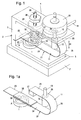
- a piezoelectric pump drive is shown schematically simplified, in which the from a lower horizontal leg 3, an upper horizontal leg 4 and the vertical connector. 5 existing frame 2 on a solid base 2 'is arranged, which gives the frame 2 the necessary stability and inertial mass to avoid natural vibration of the frame.
- a leaf spring 21 is provided in this embodiment, which is fixedly secured with one end 22 in the vertical connector 5 of the frame 2.
- this resonant spring 11 or leaf spring 21 is arranged so that it rests resiliently on the piezoelectric element 1 with a short lever arm 23.
- This is in turn arranged at a small distance from the vertical connecting piece 5 of the frame 2 on the lower horizontal leg 3, so that between the support point A and the clamped end 22 of the leaf spring 21 is a short lever arm 23.
- This leaf spring 21 is provided in this embodiment on the other side of the support point A with a longer lever arm 24, which includes the short lever arm 23 and which has a rearwardly bent end portion 25 to which a resonance mass 12 is attached to the underside.
- the end portion 25 is connected directly to a pump member 14 of a arranged on the horizontal leg 4 of the frame fluid pump 15.
- This fluid pump 15 has a horizontal outlet 16 through which the pumped fluid flows outwardly.
- a regulating spring 30 is provided, which is at a small distance from the support point A, at the the leaf spring 21 rests on the piezoelectric element 1, acts on the longer lever arm 24 of the leaf spring 21.
- the compressive force of this regulating spring 30 is adjustable and fixable by means of a seated in the upper horizontal leg 4 screw 29 with lock nut 28.
- This set screw 29 is provided at its lower end with a cylindrical receiving sleeve 33 in which the upper end of the regulating spring 30 is guided.
- the lower end of this regulating spring 30 is supported by a pressure piece 34 on the longer lever arm 24 of the leaf spring 21 so that the leaf spring 21 rests permanently on the piezoelectric element 1 under a certain prestress, that is to say resiliently.
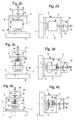
- This embodiment of the piezoelectric pump drive according to the invention can be operated both in the working position shown in FIGS. 1 and 2.
- the working position is such that the leaf spring 21 assumes a vertical standing position, while it assumes a hanging vertical position in Fig. 2b. In these positions, the weight of the resonance mass 12 or balance mass 27 does not lie on the piezoelectric element 1.
- Figures 2a and 2b represent in this case each a top view from above.
- a bent bar spring 21/4 provided from round spring wire.
- This bar spring 21/4 is fixedly secured with one end 22/4 in the vertical connector 5 of the frame.
- the longer lever arm 24/4 which here also includes the short lever arm 23/4, has a rearwardly bent end portion 25/4, on which the resonance mass 12 is attached on the underside.
- the connected by the arc 26/4 with the longer lever arm 24/4 end portion 25/4 is provided with a parallel to the lever arm 24/4 extending extension to which a balancing mass 27 is attached.
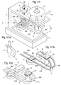
- Fig. 1 / 1c an embodiment is shown by way of example in which two curved bar springs 21/4 are provided in parallel position as resonant spring 11, 24 and 4 carry the resonance mass 12 together on the longer lever arms and their short lever arms 23/4 by a resting on the piezoelectric element 1 transverse web 122 are interconnected.
- the two rod springs 21/4 are provided with extensions 25/4, which together carry the balancing mass 27.
- this use of two bar springs 21/4 has the advantage that the oscillating system is more stable in its oscillating plane and is less prone to lateral oscillations of vibration.
- the embodiment of Fig. 1 / 1b It should be noted here that also more than two rod springs 21/4 or band-shaped springs 21/6 can be used in parallel position without further notice.
- leaf springs provided there can readily be replaced by correspondingly shaped bar springs or band-shaped springs individually or in multiple parallel arrangement, without changing the operating principle something.
- a Regulierfeder 30 which acts in an analogous manner to the upper leaf spring 21/2 and whose bias is adjustable by means of a screw 29 for Einjust réelle the natural frequency of the oscillating system.
- a lock nut 28 is provided for fixing the adjusting screw 29. Otherwise, the structure is the same as in the embodiment of FIG. 2.
- the oscillations of the oscillating system take place, as in all other exemplary embodiments, in each case in the direction of the double arrow 31.
- FIG. 3 In addition to the working position shown in Fig. 3, in which the connecting piece 5 of the frame 2 extends vertically, the working positions shown in Fig. 3a and 3b are possible in which this connecting piece 5 occupies a horizontal position and the legs 3 and 4 together each run vertically with the base 2 '. In these working positions also extend the leaf springs 21/1 and 21/2 vertically, taking a standing in the working position of Fig. 3a and a standing in the working position of Fig. 3b a hanging position.
- FIG. 3d A further working position shown in FIG. 3d is possible in that the frame 2 is positioned on the side with the base plate 2 ', so that FIG. 3 shows a plan view.
- FIG. 4 another very simple embodiment is shown schematically simplified, this differs from the embodiment of FIGS. 1 and 2 only in that the resonance mass 12 is provided on a completely flat planar resonance spring 11 in the form of a leaf spring 21/3.
- the frame 2 is formed slightly lower in this case, which means that the upper horizontal leg 4 has a smaller vertical distance from the lower horizontal leg 3 and, accordingly, the vertical connector 5 is made shorter.
- the leaf spring 21/3, the resonance mass via a plunger 13 in turn with the pump member 14 of the fluid pump 15 is force and motion transmitting connected and arranged on a longer lever arm 24 of the leaf spring 21/3. It also has this Leaf spring a resonance mass 12 outwardly projecting extension 25 ', which is provided with a balance mass 27.
- Figs. 4a and 4b that in addition to the vertical working position shown in Fig. 4, at least two other working positions are possible in which the leaf spring 21 assumes a vertical position, wherein the frame 2 in each case 90 ° is twisted in one direction or the other.
- the lateral position shown in FIG. 4d is also possible here.
- the portion of the leaf spring 21 lying on the piezo element 1 is formed as a rigid part over a region which comprises a part of the short lever arm 23 and at least part of the longer lever arm 24 is stiffened by one or both sides launched rigid plate body or by longitudinal corrugations, so that while the oscillating ability of the leaf spring 21 is maintained overall, but in this stiffened region no deflection of the leaf spring 21 can be carried out.
- This embodiment can be applied to all embodiments equipped with leaf springs 21.
- a three-legged leaf spring 21/3 is extended with its lower to the vertical connector 5 of the frame 2 out and fixed with its end 22 fixed in the same manner as the leaf spring 21 in the embodiment of FIG
- Leaf spring 21/3 thus has three in parallel position one above the other arranged legs 41, 42 and 43.
- resonance masses 12/1 and 12 ' are arranged on the legs 42 and 43, respectively.
- the extended leg 43 also carries the balancing mass 27th
- the lower horizontal leg 41 of the leaf spring 21/3 is under the influence of a pull pin 44 ', which is assigned a regulating spring 30'.
- This regulating spring 30 ' is seated in a cylindrical underside recess 48' of the lower horizontal leg 3 of the frame 2 and can with a Adjusting nut 52 are adjusted with respect to their bias.
- the natural frequency of the oscillating system can be influenced and adjusted to the operating frequency or to the working cycle of the piezoelectric element 1.
- FIG. 5 can each assume different working positions and indeed, as FIGS. 5a, 5b show, essentially the same as the embodiments of FIGS. 2 to 4.
- a further embodiment of the piezoelectric pump drive according to the invention is shown in a schematic simplification, in which the resonant spring 11 is formed as a flat leaf spring 21/5.
- This leaf spring 21/5 is mounted in a frame 2/1, which consists of a horizontal solid lower part 60, on which a bridge-like upper part 61 by means of two vertical supports 62 and 63 is placed.
- the piezoelectric element 1 is arranged centrally and indeed so that it is resiliently supported on the longitudinal center M of the leaf spring 21/5.
- This leaf spring 21/5 rests on the cutting edges of two prism-like support bearings 65 and 66, which are symmetrical to the longitudinal center M are arranged at a lateral distance from this, which corresponds to the short lever arm 23 of the leaf spring 21/5.
- the respective longer lever arms 24 project through window-like recesses 67 and 68 of the vertical supports 62 and 63 and are provided with the resonance masses 12 at their respective ends lying outside the frame 2/1. At the same time these outer ends are each connected via the plunger 13 with the pump member 14 of a fluid pump 15 force and motion transmitting. Again, the vibrations of the longer lever arms 24 of the leaf spring 21/5 take place in each case in the direction of the double arrows 31, again in synchronism with the working cycles or the operating frequency of the piezoelectric element. 1
- the two fluid pumps 15 are connected by connecting lines 17 and 18 to a common output 19.
- FIG. 7 an embodiment is shown in which two piezoelectric pump drives according to FIGS. 1 and 2 are assembled in parallel position to form a common double pumping system.
- the two lower legs 3 of the racks 2 are joined together flush on the underside and the two fluid pumps 15 are similar to the embodiment of FIG. 6 connected by connecting lines 17 and 18 to a common output 19.
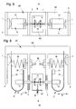
- FIGS. 8 and 9 show, it is also possible to arrange two pumping systems of the type shown in FIGS. 1 and 2 such that their resonance springs 11 operate on a common fluid pump 15/1 and at the output 16 twice the pumping power is available put.
- the respective upper and lower legs 3 and 4 are joined by a common rear connecting web 5/2 to form a common frame 2/2.
- the fluid pump 15/1 is arranged between the legs 4 of the frame 2/2.
- the vibrations of the two resonance springs 11 take place in the direction of the double arrows 31.
- FIG. 8 shows this arrangement in plan view
- FIG. 9 shows an end view X from FIG. 8 again.
- two resonant oscillation systems each acting on a fluid pump 15 are also provided, the fundamental basic construction of which corresponds to that of FIG. 8 or FIGS. 1 and 2.
- the frame 2 has only one left and one right leg 73 and 74, which are fastened vertically to a lower horizontal connecting piece 5 '.
- the fluid pumps 15 are mounted on the outside, the pump members 14 are connected via the plunger 13 with the end portions 25 of each of a bow 26 having resonant springs 11.
- these end sections 25 each carry the resonance mass 12 and the balancing masses 27 on the extensions 25 'which are directed downwards in this case.
- the spring legs 21 'again form a short lever arm 23 between the bearing part 78 and the support point A , on which they rest on the piezoelectric elements 1 resiliently and longer lever arms 24 which are connected via the arcuate portions 26 with the end portions 25.
- adjusting devices are also provided with a respective regulating spring 30 and screws 29 and lock nuts 28 which are arranged in an analogous manner as the embodiment of FIG. 2 and work.
- the two fluid pumps 15 are also connected via connecting lines 17 and 18 to a common output 19 here.
- the resonance spring is formed as a leaf spring 21 and the construction principle of Figs. 1 and 2 is realized, d. H. in the embodiments of FIGS. 2 to 4 and 5 to 10, the leverage is advantageously used to increase the work, which consists between the short lever 23 and the longer lever 24 of the leaf spring and which causes the oscillating system, the has to actuate the fluid pump 15, even at minimum deflections of the piezoelectric element 1 substantially larger vibration amplitudes executes that are used to actuate the pumping organ 14.
- a leverage is utilized.
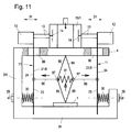
- two isosceles-like isosceles knee joints are provided, each consisting of a lower lever 85 and an upper lever 86 and a joint 87 connecting these two levers 85 and 86, wherein the Gelenk.87 is connected by a connecting rod 88 each with a leaf spring 21/6.
- the vertical deflections of the piezoelectric element 1 are converted into horizontal movements, so that the two leaf springs 21/6 each experience an outward deflection.
- both joints 87 are connected to one another by a tension spring 91, which should be adjustable.
- the two upper levers 86 of the two knee joints are supported on the underside of the leg 4.
- each longer lever arms 24 of the leaf springs 21/6 are provided with externally mounted resonance masses 12 and at the same time via plunger 13 with the pump members 14 of a double fluid pump 15/1 force and motion-transmitting connected, so that their swinging movements actuate the pumping members 14.
- the leaf springs 21/6 each protrude through recesses 89 and 90 of the upper leg 4, on which the double fluid pump 15/1 is arranged centrally.
- the natural frequency of the two leaf springs 21/6 can each be adjusted to some extent, so that here in a simple manner synchronism between the natural frequency of the two oscillating systems and the duty cycle or Working frequency of the piezoelectric element 1 can be achieved.
- the deflection amplitude of the upper leaf spring ends is approximately six times greater than the vertical deflection of the piezoelement 1.
- pumping pistons can also be used as pumping elements instead of the pumping diaphragms mentioned in the exemplary embodiments.
Landscapes
- Engineering & Computer Science (AREA)
- Mechanical Engineering (AREA)
- General Engineering & Computer Science (AREA)
- Reciprocating Pumps (AREA)
Applications Claiming Priority (1)
| Application Number | Priority Date | Filing Date | Title |
|---|---|---|---|
| DE102006043219A DE102006043219B3 (de) | 2006-09-11 | 2006-09-11 | Piezoelektrischer Pumpenantrieb |
Publications (2)
| Publication Number | Publication Date |
|---|---|
| EP1898087A2 true EP1898087A2 (fr) | 2008-03-12 |
| EP1898087A3 EP1898087A3 (fr) | 2011-05-11 |
Family
ID=38959689
Family Applications (1)
| Application Number | Title | Priority Date | Filing Date |
|---|---|---|---|
| EP07014364A Withdrawn EP1898087A3 (fr) | 2006-09-11 | 2007-07-21 | Engrenage de pompe piézoélectrique |
Country Status (2)
| Country | Link |
|---|---|
| EP (1) | EP1898087A3 (fr) |
| DE (1) | DE102006043219B3 (fr) |
Cited By (6)
| Publication number | Priority date | Publication date | Assignee | Title |
|---|---|---|---|---|
| EP2133567A3 (fr) * | 2008-06-10 | 2013-01-16 | Siegfried Richter | Commande oscillante électrique |
| US9802214B2 (en) | 2010-07-04 | 2017-10-31 | Ice-World Holding B.V. | Play fountain |
| US10166568B2 (en) | 2013-03-22 | 2019-01-01 | Hoeks Beheer B.V. | Assembly, in particular a play fountain |
| CN113482891A (zh) * | 2021-07-21 | 2021-10-08 | 合肥工业大学 | 一种谐振频率可调的音叉式驱动器驱动的压电泵 |
| CN114109786A (zh) * | 2021-12-01 | 2022-03-01 | 合肥工业大学 | 一种基于对称式同相放大机构的压电堆栈泵 |
| CN114640270A (zh) * | 2022-04-12 | 2022-06-17 | 合肥工业大学 | 一种基于菱形环和对称反相放大杆的二级驱动压电堆栈泵 |
Families Citing this family (3)
| Publication number | Priority date | Publication date | Assignee | Title |
|---|---|---|---|---|
| CN101922442A (zh) * | 2010-03-05 | 2010-12-22 | 吉林大学 | 双腔双驱动压电叠堆泵 |
| CN113007077B (zh) * | 2020-04-22 | 2022-06-07 | 合肥工业大学 | 一种阵列式压电隔膜泵 |
| CN114382682B (zh) * | 2022-01-24 | 2023-06-13 | 枣庄学院 | 双谐振柱塞泵 |
Family Cites Families (4)
| Publication number | Priority date | Publication date | Assignee | Title |
|---|---|---|---|---|
| JPS61103580U (fr) * | 1984-12-14 | 1986-07-01 | ||
| JP2887677B2 (ja) * | 1988-08-11 | 1999-04-26 | 株式会社日本計器製作所 | 圧電ポンプ |
| US6425740B1 (en) * | 2000-07-28 | 2002-07-30 | Sarcos, L.C. | Resonator pumping system |
| DE10234584B3 (de) * | 2002-07-30 | 2004-04-08 | Festo Ag & Co. | Piezoelektrisch betätigbare Pumpe |
-
2006
- 2006-09-11 DE DE102006043219A patent/DE102006043219B3/de not_active Expired - Fee Related
-
2007
- 2007-07-21 EP EP07014364A patent/EP1898087A3/fr not_active Withdrawn
Cited By (8)
| Publication number | Priority date | Publication date | Assignee | Title |
|---|---|---|---|---|
| EP2133567A3 (fr) * | 2008-06-10 | 2013-01-16 | Siegfried Richter | Commande oscillante électrique |
| US9802214B2 (en) | 2010-07-04 | 2017-10-31 | Ice-World Holding B.V. | Play fountain |
| US10166568B2 (en) | 2013-03-22 | 2019-01-01 | Hoeks Beheer B.V. | Assembly, in particular a play fountain |
| CN113482891A (zh) * | 2021-07-21 | 2021-10-08 | 合肥工业大学 | 一种谐振频率可调的音叉式驱动器驱动的压电泵 |
| CN114109786A (zh) * | 2021-12-01 | 2022-03-01 | 合肥工业大学 | 一种基于对称式同相放大机构的压电堆栈泵 |
| CN114109786B (zh) * | 2021-12-01 | 2023-07-21 | 合肥工业大学 | 一种基于对称式同相放大机构的压电堆栈泵 |
| CN114640270A (zh) * | 2022-04-12 | 2022-06-17 | 合肥工业大学 | 一种基于菱形环和对称反相放大杆的二级驱动压电堆栈泵 |
| CN114640270B (zh) * | 2022-04-12 | 2024-04-30 | 合肥工业大学 | 一种基于菱形环和对称反相放大杆的二级驱动压电堆栈泵 |
Also Published As
| Publication number | Publication date |
|---|---|
| DE102006043219B3 (de) | 2008-02-28 |
| EP1898087A3 (fr) | 2011-05-11 |
Similar Documents
| Publication | Publication Date | Title |
|---|---|---|
| EP1898087A2 (fr) | Engrenage de pompe piézoélectrique | |
| EP2133567B1 (fr) | Commande oscillante électrique | |
| DE3926348C2 (fr) | ||
| DE2830694C2 (de) | Tintentröpfchen-Druckkopf | |
| EP1991777A1 (fr) | Compresseur linéaire et mécanisme d'entraînement pour ledit compresseur | |
| DE3030639A1 (de) | Vibrator | |
| EP1539437A1 (fr) | Petit electromenager comprenant un dispositif d'entrainement destine a produire un mouvement oscillatoire | |
| EP3389912B1 (fr) | Machine de soudage par friction linéaire | |
| DE60309560T2 (de) | Linearantrieb für schwingende Einrichtung | |
| EP1454679A1 (fr) | Dispositif de tamisage | |
| EP3469703A1 (fr) | Moteur à ultrasons | |
| EP2208693A2 (fr) | Convoyeur linéaire de vibrations | |
| EP2022734B1 (fr) | Convoyeur linéaire de vibrations | |
| AT511949A4 (de) | Spannwellensieb | |
| EP1142651A2 (fr) | Dispositif de tamisage | |
| DE602004003579T2 (de) | Flexible verbindungsglieder für eine maschine umfassende erntevorrichtung zum ernten von früchten, beeren und dergleichen | |
| WO2010076113A1 (fr) | Entraînement oscillant | |
| DE102007031639B4 (de) | Vibrationslinearförderer | |
| EP0794136B1 (fr) | Convoyeur vibratoire utilisant la fréquence de résonance | |
| DE2045152C3 (de) | Schwingmotor mit bilaminaren Biegeschwingern für elektrisch angetriebene Trockenrasierapparate | |
| DE102007023963B4 (de) | Vorrichtung für einen Schwingungserreger | |
| DE202013008780U1 (de) | Spannwellensiebvorrichtung | |
| DE4236574C2 (de) | Linearaktuator | |
| DE3786067T2 (de) | Vorrichtung zum Zerbrechen einer Fläche. | |
| DE102011054300A1 (de) | Linear-Vibrationsförderer |
Legal Events
| Date | Code | Title | Description |
|---|---|---|---|
| PUAI | Public reference made under article 153(3) epc to a published international application that has entered the european phase |
Free format text: ORIGINAL CODE: 0009012 |
|
| AK | Designated contracting states |
Kind code of ref document: A2 Designated state(s): AT BE BG CH CY CZ DE DK EE ES FI FR GB GR HU IE IS IT LI LT LU LV MC MT NL PL PT RO SE SI SK TR |
|
| AX | Request for extension of the european patent |
Extension state: AL BA HR MK YU |
|
| PUAL | Search report despatched |
Free format text: ORIGINAL CODE: 0009013 |
|
| AK | Designated contracting states |
Kind code of ref document: A3 Designated state(s): AT BE BG CH CY CZ DE DK EE ES FI FR GB GR HU IE IS IT LI LT LU LV MC MT NL PL PT RO SE SI SK TR |
|
| AX | Request for extension of the european patent |
Extension state: AL BA HR MK RS |
|
| STAA | Information on the status of an ep patent application or granted ep patent |
Free format text: STATUS: THE APPLICATION HAS BEEN WITHDRAWN |
|
| 18W | Application withdrawn |
Effective date: 20111109 |