EP1898094B1 - Procédé de pompage de fluide avec une pompe péristaltique - Google Patents
Procédé de pompage de fluide avec une pompe péristaltique Download PDFInfo
- Publication number
- EP1898094B1 EP1898094B1 EP07024651A EP07024651A EP1898094B1 EP 1898094 B1 EP1898094 B1 EP 1898094B1 EP 07024651 A EP07024651 A EP 07024651A EP 07024651 A EP07024651 A EP 07024651A EP 1898094 B1 EP1898094 B1 EP 1898094B1
- Authority
- EP
- European Patent Office
- Prior art keywords
- fluid
- rollers
- roller assembly
- peristaltic pump
- door
- Prior art date
- Legal status (The legal status is an assumption and is not a legal conclusion. Google has not performed a legal analysis and makes no representation as to the accuracy of the status listed.)
- Expired - Lifetime
Links
- 239000012530 fluid Substances 0.000 title claims abstract description 64
- 230000002572 peristaltic effect Effects 0.000 title claims abstract description 56
- 238000000034 method Methods 0.000 title claims abstract description 15
- 238000005086 pumping Methods 0.000 title claims abstract description 13
- 235000015116 cappuccino Nutrition 0.000 claims description 2
- 235000013353 coffee beverage Nutrition 0.000 claims description 2
- 235000015205 orange juice Nutrition 0.000 claims description 2
- 238000010790 dilution Methods 0.000 claims 3
- 239000012895 dilution Substances 0.000 claims 3
- 239000000463 material Substances 0.000 description 7
- 239000012141 concentrate Substances 0.000 description 5
- 230000013011 mating Effects 0.000 description 5
- DHKHKXVYLBGOIT-UHFFFAOYSA-N 1,1-Diethoxyethane Chemical compound CCOC(C)OCC DHKHKXVYLBGOIT-UHFFFAOYSA-N 0.000 description 3
- 229920004943 Delrin® Polymers 0.000 description 3
- 239000011354 acetal resin Substances 0.000 description 3
- 235000013361 beverage Nutrition 0.000 description 3
- 229920000515 polycarbonate Polymers 0.000 description 3
- 239000004417 polycarbonate Substances 0.000 description 3
- 229920000642 polymer Polymers 0.000 description 3
- 229920006324 polyoxymethylene Polymers 0.000 description 3
- 239000002131 composite material Substances 0.000 description 2
- 239000002184 metal Substances 0.000 description 2
- 229910052751 metal Inorganic materials 0.000 description 2
- 229920001296 polysiloxane Polymers 0.000 description 2
- 239000004698 Polyethylene Substances 0.000 description 1
- NIXOWILDQLNWCW-UHFFFAOYSA-N acrylic acid group Chemical group C(C=C)(=O)O NIXOWILDQLNWCW-UHFFFAOYSA-N 0.000 description 1
- 239000000654 additive Substances 0.000 description 1
- 230000000996 additive effect Effects 0.000 description 1
- 230000008602 contraction Effects 0.000 description 1
- 239000003085 diluting agent Substances 0.000 description 1
- 235000013305 food Nutrition 0.000 description 1
- 239000007788 liquid Substances 0.000 description 1
- 150000002739 metals Chemical class 0.000 description 1
- -1 polyethylene Polymers 0.000 description 1
- 229920000573 polyethylene Polymers 0.000 description 1
Images
Classifications
-
- F—MECHANICAL ENGINEERING; LIGHTING; HEATING; WEAPONS; BLASTING
- F04—POSITIVE - DISPLACEMENT MACHINES FOR LIQUIDS; PUMPS FOR LIQUIDS OR ELASTIC FLUIDS
- F04B—POSITIVE-DISPLACEMENT MACHINES FOR LIQUIDS; PUMPS
- F04B43/00—Machines, pumps, or pumping installations having flexible working members
- F04B43/12—Machines, pumps, or pumping installations having flexible working members having peristaltic action
- F04B43/1253—Machines, pumps, or pumping installations having flexible working members having peristaltic action by using two or more rollers as squeezing elements, the rollers moving on an arc of a circle during squeezing
-
- A—HUMAN NECESSITIES
- A61—MEDICAL OR VETERINARY SCIENCE; HYGIENE
- A61M—DEVICES FOR INTRODUCING MEDIA INTO, OR ONTO, THE BODY; DEVICES FOR TRANSDUCING BODY MEDIA OR FOR TAKING MEDIA FROM THE BODY; DEVICES FOR PRODUCING OR ENDING SLEEP OR STUPOR
- A61M5/00—Devices for bringing media into the body in a subcutaneous, intra-vascular or intramuscular way; Accessories therefor, e.g. filling or cleaning devices, arm-rests
- A61M5/14—Infusion devices, e.g. infusing by gravity; Blood infusion; Accessories therefor
- A61M5/142—Pressure infusion, e.g. using pumps
- A61M5/14212—Pumping with an aspiration and an expulsion action
- A61M5/14232—Roller pumps
Definitions
- the present invention relates generally to a pump and more particularly relates to a peristaltic pump that provides quick and sanitary loading of a fluid tube.
- a peristaltic pump includes a number of pads, drums, or arms rotating within a pair of outer discs.
- a tube with a fluid to be transported therein generally is positioned adjacent to the drums and a fixed outer surface. As the drums rotate, the fluid within the tube is pushed along and caused to move through the tube. In other words, the fluid is forced along by means of contractions produced mechanically on the flexible tubing.
- Peristaltic pumps have been used in the beverage industry with respect to varying types of fluids.
- One issue associated with a peristaltic pump is the loading and unloading the fluid tube. Loading the tube may be relatively uncomplicated in that the rollers may advance the tube through the overall housing of the pump. Unloading the tube, however, may result in some spillage of the fluid within the housing of the pump.
- a peristaltic pump generally provides a fixed number of rollers and a fixed pump speed see e.g. the prior art document US-4,558,996 .
- the pump may not accommodate fluids of varying viscosity or the desire for varying pump speeds.
- the pump generally is designed for one specific type of fluid
- Such a pump may be quickly and easily modified for varying fluids and speeds.
- the present invention thus provides a peristaltic pump for transporting a fluid within a flexible tube having a first end, a middle portion, and a second end.
- the peristaltic pump may include a roller assembly positioned for rotation, a first door positioned adjacent to the roller assembly and pivotable about a first direction, and a second door positioned adjacent to the roller assembly and pivotable about a second direction.
- the first door and the second door may pivot open and the middle portion of the flexible tube may be positioned about the roller assembly.
- the peristaltic pump further may include a base such that the roller assembly may be positioned therein and the doors may be pivotably attached thereto.
- the base may include a tube inlet and a tube outlet positioned thereon.
- the base also may include an indent for the roller assembly to be positioned therein.
- the base may include a number of base hinges for pivoting the doors.
- the doors may include hinges for pivoting about the base.
- the first door may include a wall positioned adjacent to the roller assembly so as to define a tube run therein.
- the second door may include a tube guide positioned thereon.
- the second door may include an indent for the roller assembly to be positioned therein.
- the peristaltic pump may include locking mean positioned thereon for the first door and the second door.
- the base, the first door, and/or the second door may be made out of an acetal resin.
- the roller assembly may include a number of rollers mounted on a number of discs.
- the discs may include a number of roller mounting locations such that the number of rollers may be modified.
- the roller assembly may include a number of replaceable rollers.
- the peristaltic pump further may include a pump motor in communication with the roller assembly.
- the pump motor may be a variable speed motor.
- a method of the present invention may provide for pumping a fluid within a flexible tubing with a peristaltic pump.
- the peristaltic pump may have a pump motor and a roller assembly.
- the method may include selecting a first predetermined fluid, selecting a first speed for the pump motor based upon the first predetermined type of fluid, selecting a first number of rollers for the roller assembly based upon the first predetermined type of fluid, and pumping the first predetermined type of fluid with the first speed and the first number of rollers.
- the method further may include selecting a second predetermined fluid, a second speed for the pump motor, and a second number of rollers and pumping the second predetermined type of fluid with the second speed and second number of rollers.
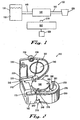
- Fig. 1 shows a schematic view a peristaltic pump system 100 of the present invention.
- the peristaltic pump system 100 moves a fluid 110.
- the fluid 110 may be a beverage, a concentrate, an additive, or any other type of liquid.
- the present invention is not limited by the nature or the flow characteristics of the fluid 110.
- the peristaltic pump system 100 may be used with a fluid or fluids 110 of varying viscosities and/or other types of flow characteristics.
- the fluid 110 may be held in a fluid container 120.
- the fluid container 120 may be any structure designed to hold a fluid 110, including a bag in box or other type of beverage or concentrate container.
- the peristaltic pump system 100 may transport the fluid 110 from the fluid container 120 to a dispensing area 130.
- the dispensing area 130 may be a cup or other type of container, a mixing area, or any other type of destination.
- the peristaltic pump system 100 may move the fluid 110 from the fluid container 120 to the dispensing area 130 via a length of flexible tubing 140.
- the flexible tubing 1.40 may be made out of silicone, silicone composite, or similar types of polymers.
- the flexible tubing 140 preferably is made out of food grade material.
- the flexible tubing 140 may have any desired length and/or diameter.
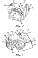
- Figs. 2 through 5 show a peristaltic pump 150 for use with the peristaltic pump system 100.
- the peristaltic pump 150 may include a base 160.
- the base 160 may include a tube inlet 170 and a tube outlet 180.
- the tube inlet 170 and the tube outlet 180 may be formed within the base 160 and may be sized to accommodate the diameter of the flexible tubing 140.
- the tube inlet 170 and the tube outlet 180 may be spaced apart by about ninety degrees (90°) to about one hundred eighty degrees (180°). Any angle between zero (0°) and one hundred eighty (180°), however, may be used.
- the base 160 also may have a roller assembly indent 190.
- the roller assembly indent 190 may be sized to accommodate a roller assembly as described below.
- the indent 190 may have the diameter of about 5.3 to about 14 centimeters and may have a depth of about 30 to about 50 millimeters. Any diameter or depth, however, may be used so as to accommodate the shape and size of the roller assembly.
- the roller assembly indent 190 may have a motor shaft aperture 200 so as to accommodate a motor shaft as described below. The size of the aperture 200 depends upon the size of the motor shaft.
- the base 160 further may have a number of hinges, a first hinge 210 and a second hinge 220.
- the hinges 210,220 may be made out of shafts and/or cylinders designed to accommodate the shafts.
- the first hinge 210 of the base 160 has a shaft 215 extending vertically and the second hinge 220 has a cylinder 225 extending horizontally. Any orientation of shafts and/or cylinders, however, may be used.
- the peristaltic pump 150 further may include a door 230.
- the door 230 may be positioned on and enclose the base 160.
- the door 230 may have a hinge 240 that accommodates the first hinge 210 of the base 160.
- the hinge 240 may include a shaft or a cylinder to accommodate a shaft.
- the shaft 215 of the first hinge 210 of the base 160 accommodates a cylinder 245 of the door 230.
- the door 230 further may include a wall 250.
- the wall 250 may include a first side 260 and a second side 270.
- the first side 260 may accommodate a tube run 280.
- the tube run 280 may be sized to accommodate the flexible tubing 140 between a roller assembly as described below and the position of the first side 260 of the wall 250 so as to provide the pumping action as described below.
- the wall 250 preferably is substantially semicircular shaped.
- the door 230 may extend from the hinge 240 about the base 160 to about the tube outlet 180.
- the door 230 further may have a mating end 290 designed for a snap fit or other type of mating about the tube outlet 180 of the base 160.
- the peristaltic pump 150 further may include a lid 300.
- the lid 300 may be sized to accommodate the size and shape of the base 160.
- the lid 300 also may have a hinge 310.
- the hinge 310 may accommodate the second hinge 220 of the base 160.
- the hinge 310 may include a shaft 315 to accommodate the cylinder 225 of the second hinge 220.
- the lid 300 further may include a number of tube guides 320.
- the tube guides 320 may be sized to accommodate the flexible tubing 140 therein.
- the lid 300 further may include a lock aperture 330.
- the lock aperture 330 may coordinate with the shaft 215 of the first hinge 210 of the base 160.
- a nut 335 or other type of locking device may be attached to the shaft 215 so as to lock the lid 300 in place.
- the lid 300 further may include a roller assembly indent 340 similar to the roller assembly indent 190 described below with respect to the base 160.
- the roller assembly indent 340 of the lid 300 also may be sized to accommodate the roller assembly as described below.
- the components of the peristaltic pump 150 in general, and the base 160, the door 230, and the lid 300 in specific, may be made out of polymers, composites, metals or any other type sufficiently rigid materials.
- polymers, composites, metals or any other type sufficiently rigid materials For example, polycarbonate, polyethylene, acrylic or similar types of materials may be used.
- the base 160, the door 230, and the lid 300 also may be made out of Delrin®, an acetal resin sold by E. I. Dupont de Nemours & Company of Wilmington, Delaware.
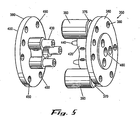
- the peristaltic pump 150 also may include a roller assembly 350 as is shown in, for example, Fig. 5 .
- the roller assembly 350 may include a number of rollers 360.
- the rollers 360 also may be made out of Delrin® or similar materials. Further, the rollers 360 also may be made out of any material with good wear characteristics such as polycarbonate, Delrin®, or similar types of materials.
- the rollers 360 may have a diameter of about ten (10) to about thirty (30) millimeters and a length of about 28 to 35 centimeters.
- the rollers 360 may have any desired size or shape. The diameter of the rollers 360 may be adjusted to accommodate the diameter of the flexible tube 140.
- rollers 360 generally are used, although any number of rollers 360 may be used.
- Each roller 360 may have an axle 370 either extending therethrough or molded into each roller 360 and extending out of the lateral ends thereof.
- the axles 370 may have any convenient size.
- the roller assembly 340 also may include a number of outer discs 380.
- the discs 380 hold both ends of the rollers 360 in place.
- the discs 380 also may be made out of polycarbonate or any other type of polymer, metal, or other materials with sufficiently rigid characteristics. As is shown, a first disc 390 and a second disc 400 may be used.
- the discs 380 may have a number of mating members 410 positioned thereon.
- the first disc 390 may have a number of female members 420 while the second disc 400 has a number of male members 430.
- each of the mating members 410 also may include an internal member 440.
- the mating members 410 may be arrange in any desired order so as to ensure that the discs 380 stay attached.
- the discs 380 also may include a number of roller apertures 450 positioned or formed therein.
- the roller apertures 450 may be sized so as to accommodate the axles 370 of the rollers 360. Any number of roller apertures 450 may be used so as to vary the number of rollers 360 that the roller assembly 350 as a whole may use.
- One of the discs 390,400 also may have drive shaft aperture 460 positioned therein so as to accommodate a drive shaft as described below. In this embodiment, the first disc 390 may have the aperture 460 positioned therein.
- the first disc 390 may be positioned within the roller assembly indent 190 of the base 160 while the second disc 400 may be positioned within the roller assembly indent 340 of the lid 300.
- the roller assembly 350 thus may rotate within the base 160 and the lid 300.
- the peristaltic pump system 100 further may include a pump motor 500.
- the pump motor 500 may be a conventional DC motor or similar type of device.
- the motor 500 may be about a twenty four (24) volt DC motor.
- the pump motor 500 also may be a servomotor, a gear motor with a controller, an AC motor, and similar types of drive devices.
- the speed of the motor 500 preferably is adjustable.
- the speed of the pump motor 500 may range from about one (1) rpm to about 140 rpm.
- the pump motor 500 may include a drive shaft 510 so as to provide rotational force.
- Operation of the pump motor 500 and the peristaltic pump system 100 as a whole may be controlled by a control system 520.
- the control system 520 may vary the speed of the motor 500 and the time of operation.
- the control system 520 may include a microprocessor or a similar type of control device.
- the desired number of rollers 360 may be inserted within the roller assembly 350.
- the roller assembly 350 is then positioned within the roller assembly indent 190 of the base 160 and mounted on to the drive shaft 510 of the pump motor 500.
- the controller 520 may be set with a predetermined speed for the pump motor 500.
- the flexible tubing 140 may then be inserted within the tube inlet 170 of the base 160.
- the tubing 140 may then be wrapped around the roller assembly 350 along the tube run 280 and out via the tube outlet 180.
- the door 230 may then be closed such that the tubing 140 is positioned between the second side 270 of the door 230 and the roller assembly 350.
- the lid 300 may then be closed and locked.
- the pump motor 500 then may be activated such that the peristaltic pump system 100 pumps the fluid 510 from the fluid container 120 through the flexible tubing 140 to the dispensing area 130.
- the flexible tubing 140 may be removed from the peristaltic pump system 100. Specifically, the lid 300 may be unlocked and opened. The door 230 also may be swung open and the tubing 140 may be removed from the tube outlet 180 and the tube inlet 170. Any open ends of the tubing 140 may be pinched off if needed. Such open ends, however, need not travel through the peristaltic pump system 100. A new tube 140 may then be installed. The tubing 140 thus may be installed and removed without any spillage of the fluid 110.
- the number of the rollers 360 and the speed of the pump motor 500 may be varied according to the flow characteristics of the fluid 110 to be used.
- coffee may have a diluent to concentrate ratio of about 30 to 1 and may use about three (3) to about four (4) rollers 360 with a pump motor 500 speed of about thirty (30) to about seventy (70) rpm, with about 64 rpm preferred.
- Orange juice concentrate may be more viscous such that a ratio of about 5 to 1 may be used.
- the pump 150 therefore may use about two (2) to about three (3) rollers 360 and operate at about forty five (45) to about one hundred twenty (120) rpm, with about 82 rpm preferred.
- Cappuccino concentrate may be more viscous still and have a ratio of about two (2) to about one (1).
- the pump 150 again may only use about two (2) rollers 360, but run at a higher speed of about 95 rpm.
- the pump 150 thus can accommodate such varying flow characteristic of the fluid 110.
Landscapes
- Engineering & Computer Science (AREA)
- Mechanical Engineering (AREA)
- General Engineering & Computer Science (AREA)
- Reciprocating Pumps (AREA)
- Details Of Reciprocating Pumps (AREA)
- External Artificial Organs (AREA)
Claims (8)
- Procédé de pompage d'un fluide (110) dans un tubage flexible (140) avec une pompe péristaltique (100) ayant un moteur de pompe (500) et un ensemble de rouleau (350) qui peut comprendre un nombre variable de rouleaux (360), comprenant le fait de :sélectionner un premier fluide prédéterminé ;sélectionner une première vitesse pour le moteur de pompe (500) selon le premier type de fluide prédéterminé ;sélectionner un premier nombre de rouleaux (360) pour l'ensemble de rouleau (350) selon le premier type de fluide prédéterminé ; etpomper le premier type de fluide prédéterminé avec la première vitesse et le premier nombre de rouleaux (360).
- Procédé selon la revendication 1, comprenant en outre de sélectionner un second fluide prédéterminé, une seconde vitesse pour le moteur de pompe (500), et un second nombre de rouleaux (360) et de pomper le second type de fluide prédéterminé avec la seconde vitesse et le second nombre de rouleaux (360).
- Procédé selon la revendication 1 ou 2, dans lequel le premier type de fluide prédéterminé a un rapport de dilution d'environ 30 à 1, la première vitesse est d'environ 30 à environ 70 tr/min, et le premier nombre de rouleaux est de trois (3) ou quatre (4) rouleaux.
- Procédé selon la revendication 1 ou 2, dans lequel le premier type de fluide prédéterminé a un rapport de dilution d'environ 5 à 1, la première vitesse est d'environ 45 à environ 100 tr/min, et le premier nombre de rouleaux est de deux (2) ou trois (3) rouleaux.
- Procédé selon la revendication 1 ou 2, dans lequel le premier type de fluide prédéterminé a un rapport de dilution d'environ 2 à 1, la première vitesse est d'environ 95 tr/min, et le premier nombre de rouleaux est de deux (2) rouleaux (360).
- Procédé selon la revendication 3, dans lequel le premier type de fluide prédéterminé comprend du café.
- Procédé selon la revendication 1, dans lequel le premier type de fluide prédéterminé comprend du jus d'orange.
- Procédé selon la revendication 1, dans lequel premier type de fluide prédéterminé comprend du cappuccino.
Applications Claiming Priority (2)
| Application Number | Priority Date | Filing Date | Title |
|---|---|---|---|
| US10/628,848 US7223079B2 (en) | 2003-07-28 | 2003-07-28 | Quick loading peristaltic pump |
| EP04755973A EP1649167B1 (fr) | 2003-07-28 | 2004-06-23 | Pompe peristaltique a chargement rapide |
Related Parent Applications (1)
| Application Number | Title | Priority Date | Filing Date |
|---|---|---|---|
| EP04755973A Division EP1649167B1 (fr) | 2003-07-28 | 2004-06-23 | Pompe peristaltique a chargement rapide |
Publications (3)
| Publication Number | Publication Date |
|---|---|
| EP1898094A2 EP1898094A2 (fr) | 2008-03-12 |
| EP1898094A3 EP1898094A3 (fr) | 2008-03-26 |
| EP1898094B1 true EP1898094B1 (fr) | 2009-03-25 |
Family
ID=34103464
Family Applications (2)
| Application Number | Title | Priority Date | Filing Date |
|---|---|---|---|
| EP04755973A Expired - Lifetime EP1649167B1 (fr) | 2003-07-28 | 2004-06-23 | Pompe peristaltique a chargement rapide |
| EP07024651A Expired - Lifetime EP1898094B1 (fr) | 2003-07-28 | 2004-06-23 | Procédé de pompage de fluide avec une pompe péristaltique |
Family Applications Before (1)
| Application Number | Title | Priority Date | Filing Date |
|---|---|---|---|
| EP04755973A Expired - Lifetime EP1649167B1 (fr) | 2003-07-28 | 2004-06-23 | Pompe peristaltique a chargement rapide |
Country Status (12)
| Country | Link |
|---|---|
| US (1) | US7223079B2 (fr) |
| EP (2) | EP1649167B1 (fr) |
| JP (2) | JP4869071B2 (fr) |
| CN (2) | CN1829860A (fr) |
| AT (1) | ATE405745T1 (fr) |
| BR (1) | BRPI0413010B1 (fr) |
| DE (2) | DE602004015997D1 (fr) |
| ES (2) | ES2308211T3 (fr) |
| MX (1) | MXPA06000862A (fr) |
| RU (1) | RU2341684C2 (fr) |
| WO (1) | WO2005017359A1 (fr) |
| ZA (1) | ZA200600731B (fr) |
Cited By (1)
| Publication number | Priority date | Publication date | Assignee | Title |
|---|---|---|---|---|
| CN103244391A (zh) * | 2013-05-09 | 2013-08-14 | 天津市协达伟业电子有限公司 | 延长蠕动泵弹性软管使用寿命的方法及其装置 |
Families Citing this family (45)
| Publication number | Priority date | Publication date | Assignee | Title |
|---|---|---|---|---|
| FR2872554B1 (fr) * | 2004-06-30 | 2008-09-19 | Millipore Corp | Pompe peristaltique comportant des organes de mise en position d'un tube |
| US7556481B2 (en) * | 2005-08-26 | 2009-07-07 | Baxter International Inc. | Rotary axial peristaltic pumps and related methods |
| EP1785074B1 (fr) * | 2005-11-11 | 2008-01-23 | Gruppo Cimbali S.p.A. | Dispositif automatique pour chauffer et faire mousser du lait |
| US8480625B2 (en) * | 2006-10-23 | 2013-07-09 | Bausch & Lamb Incorporated | Grooved aspiration pump roller-head assembly |
| EP2014259A1 (fr) * | 2007-07-09 | 2009-01-14 | Astra Tech AB | Implant de tissu osseux comportant des ions de lithium |
| EP2014319A1 (fr) * | 2007-07-09 | 2009-01-14 | Astra Tech AB | Implant de tissu osseux comprenant des ions de strontium |
| US8062008B2 (en) | 2007-09-27 | 2011-11-22 | Curlin Medical Inc. | Peristaltic pump and removable cassette therefor |
| US8083503B2 (en) | 2007-09-27 | 2011-12-27 | Curlin Medical Inc. | Peristaltic pump assembly and regulator therefor |
| US7934912B2 (en) | 2007-09-27 | 2011-05-03 | Curlin Medical Inc | Peristaltic pump assembly with cassette and mounting pin arrangement |
| US8550310B2 (en) * | 2007-12-05 | 2013-10-08 | Bunn-O-Matic Corporation | Peristaltic pump |
| EP2253345B1 (fr) * | 2008-02-28 | 2012-10-17 | JMS Co., Ltd. | Dispositif d'injection pour supplément nutritionnel semi-solidifié |
| JP2010043600A (ja) * | 2008-08-12 | 2010-02-25 | Osada Res Inst Ltd | ローラポンプ |
| DE102009000299A1 (de) | 2009-01-19 | 2010-07-22 | Robert Bosch Gmbh | Schlauchpumpe |
| DE102009046406B4 (de) * | 2009-11-04 | 2012-04-26 | Fresenius Medical Care Deutschland Gmbh | Schlauchpumpe |
| US9103340B2 (en) * | 2009-11-11 | 2015-08-11 | Swan Analytische Instrumente Ag | Peristaltic pump and hose cartridge therefor |
| US9518576B1 (en) * | 2010-07-15 | 2016-12-13 | Elemental Scientific, Inc. | Peristaltic pump |
| KR101334038B1 (ko) * | 2011-05-20 | 2013-12-03 | 이재근 | 굼틀-물자새 |
| US8459968B2 (en) * | 2011-09-19 | 2013-06-11 | Curlin Medical Inc. | Peristaltic pump cassette and method of installing same |
| DE102012105926A1 (de) * | 2012-07-03 | 2014-01-09 | B. Braun Avitum Ag | Schlauchrollenpumpe mit schwenkbarer Schlauchaufnahme, und medizinisches Gerät für extrakorporale Blutbehandlung |
| DE102013102129B4 (de) | 2013-03-05 | 2024-09-19 | Vitesco Technologies GmbH | Pumpe zur Förderung einer Flüssigkeit mit verformbarer Membran sowie Kraftfahrzeug |
| CN103790809A (zh) * | 2014-01-17 | 2014-05-14 | 杭州泰林生物技术设备有限公司 | 蠕动泵系统 |
| DE102014104320B3 (de) * | 2014-03-27 | 2015-08-06 | Ulrich Gmbh & Co. Kg | Schlauchpumpe mit Ausfädeleinrichtung |
| JP5863871B2 (ja) | 2014-04-15 | 2016-02-17 | 日機装株式会社 | 装着部材及びしごき型ポンプ |
| US9784263B2 (en) | 2014-11-06 | 2017-10-10 | Zoll Circulation, Inc. | Heat exchange system for patient temperature control with easy loading high performance peristaltic pump |
| JP6800848B2 (ja) * | 2014-11-06 | 2020-12-16 | ゾール サーキュレイション インコーポレイテッドZOLL Circulation,Inc. | ポンプ |
| US11359620B2 (en) | 2015-04-01 | 2022-06-14 | Zoll Circulation, Inc. | Heat exchange system for patient temperature control with easy loading high performance peristaltic pump |
| CN104895779B (zh) * | 2015-06-09 | 2017-11-07 | 常州普瑞流体技术有限公司 | 一种不锈钢蠕动泵泵头 |
| EP3355780B1 (fr) * | 2015-10-02 | 2025-07-30 | Koninklijke Philips N.V. | Raccord pour navigation de dispositif à fil-guide de détection de forme optique |
| SE540068C2 (en) * | 2016-06-07 | 2018-03-13 | Haurir Medical Ab | Body drainage apparatus with rotatable peristaltic pump |
| US10578096B2 (en) | 2016-06-30 | 2020-03-03 | Cole-Parmer Instrument Company Llc | Peristaltic pumphead and methods for assembly thereof |
| DE102016114958A1 (de) * | 2016-08-11 | 2018-02-15 | B. Braun Avitum Ag | Peristaltikpumpe mit modularem Gehäuse |
| US10947964B2 (en) * | 2017-06-16 | 2021-03-16 | Aav Llc | System and method for precision fluid delivery |
| JP6462077B1 (ja) | 2017-09-07 | 2019-01-30 | 日機装株式会社 | 血液浄化装置及びその気泡の排出方法 |
| JP6464238B1 (ja) | 2017-09-07 | 2019-02-06 | 日機装株式会社 | 血液浄化装置及びその気泡の排出方法 |
| DE102018121868A1 (de) | 2018-09-07 | 2020-03-12 | Fresenius Medical Care Deutschland Gmbh | Peristaltische Pumpe |
| DE102018121903A1 (de) | 2018-09-07 | 2020-03-12 | Fresenius Medical Care Deutschland Gmbh | Peristaltische Pumpe |
| DE102018121872A1 (de) | 2018-09-07 | 2020-03-12 | Fresenius Medical Care Deutschland Gmbh | Peristaltische Pumpe |
| EP3880964B1 (fr) * | 2018-11-14 | 2022-07-13 | Husqvarna Ab | Pompe à fluide |
| US11147913B2 (en) | 2018-12-06 | 2021-10-19 | Curlin Medical Inc. | Platen for peristaltic infusion pump |
| JP7480982B2 (ja) * | 2020-01-31 | 2024-05-10 | サーパス工業株式会社 | チューブポンプ |
| DE102020106372A1 (de) * | 2020-03-09 | 2021-09-09 | Ulrich Gmbh & Co. Kg | Schlauchpumpe |
| ES2877948A1 (es) * | 2020-11-09 | 2021-11-17 | Pacheco Luis Alonso | Bomba peristáltica para histeroscopia |
| US20230279849A1 (en) * | 2022-03-07 | 2023-09-07 | Robert Hordis | Peristaltic pump |
| US20250137449A1 (en) * | 2023-10-30 | 2025-05-01 | Hydration Labs, Inc. | Monitoring pump speeds of peristaltic pumps |
| CN119367632B (zh) * | 2024-11-05 | 2026-01-20 | 中国人民解放军陆军军医大学第二附属医院 | 一种自动腹膜透析设备 |
Family Cites Families (30)
| Publication number | Priority date | Publication date | Assignee | Title |
|---|---|---|---|---|
| GB851474A (en) | 1956-02-22 | 1960-10-19 | Allman Patents Ltd | Liquid spraying apparatus |
| US3447478A (en) * | 1967-03-03 | 1969-06-03 | Miles Lab | Peristaltic pump |
| US3963023A (en) * | 1974-11-04 | 1976-06-15 | Cobe Laboratories, Inc. | Extracorporeal blood circulation system and pump |
| GB1578022A (en) * | 1976-05-05 | 1980-10-29 | Iles F | Peristaltic pumps |
| GB2069063A (en) | 1980-02-04 | 1981-08-19 | Lenton D F | Improvements in peristaltic pumps |
| US4432707A (en) * | 1982-06-21 | 1984-02-21 | Anko Motors, Inc. | Roller assembly for peristaltic pump |
| US4549860A (en) * | 1983-04-04 | 1985-10-29 | Yakich Sam S | Blood pump improvements |
| US4558996A (en) * | 1983-06-30 | 1985-12-17 | Organon Teknika Corporation | Easy load peristaltic pump |
| US4573887A (en) * | 1983-09-16 | 1986-03-04 | S. E. Rykoff & Co. | Corrosion-resistant roller-type pump |
| JPS62113558A (ja) * | 1985-11-13 | 1987-05-25 | Canon Inc | インクジエツト記録装置 |
| JPS6369789A (ja) * | 1986-09-12 | 1988-03-29 | 伊藤 勝之 | 脱水汚泥ケ−キを肥料化する製造法 |
| JPS6371487A (ja) * | 1986-09-12 | 1988-03-31 | 本田技研工業株式会社 | 自動二輪車のラジエ−タ |
| JPS6392092A (ja) * | 1986-10-06 | 1988-04-22 | 松下電器産業株式会社 | 多層配線板の製造方法 |
| JPS6436682A (en) * | 1987-07-31 | 1989-02-07 | Sharp Kk | Reversible temperature indicating material |
| JP2596769B2 (ja) * | 1987-12-24 | 1997-04-02 | 株式会社平和 | パチンコ機 |
| US4832584A (en) * | 1988-01-15 | 1989-05-23 | Corpak, Inc. | Rotor for peristaltic pump |
| US5211548A (en) * | 1989-07-31 | 1993-05-18 | Terumo Kabushiki Kaisha | Peristaltic pump having a motor overload protector |
| US5098261A (en) * | 1990-05-04 | 1992-03-24 | Brandel Corporation | Peristaltic pump and method for adjustable flow regulation |
| JPH0544656A (ja) * | 1991-08-09 | 1993-02-23 | Tabai Espec Corp | チユービングポンプ |
| RU2031247C1 (ru) * | 1992-03-17 | 1995-03-20 | Сергей Егорович Косарев | Перистальтический насос |
| DE4214914A1 (de) * | 1992-05-11 | 1993-11-18 | Allweiler Ag | Schlauchpumpe |
| US5342181A (en) * | 1992-06-15 | 1994-08-30 | Datascope Investment Corp. | Single roller blood pump and pump/oxygenator system using same |
| GB2285837B (en) * | 1994-01-24 | 1998-05-13 | Varian Australia | Peristaltic pump |
| US5388972A (en) * | 1994-03-09 | 1995-02-14 | Medical Laboratory Automation, Inc. | Peristaltic pump with removable tubing of precise length |
| US5803317A (en) * | 1996-02-09 | 1998-09-08 | Wheeler; James R. | Heated dispensing apparatus |
| US5879144A (en) * | 1996-08-14 | 1999-03-09 | Sims Deltec, Inc. | Pressure plate adaptors and methods |
| DE19647867C2 (de) | 1996-11-19 | 1999-06-17 | Fraunhofer Ges Forschung | Schlauchpumpe |
| US6041709A (en) * | 1998-11-12 | 2000-03-28 | Usadvantage, Inc. | Peristaltic pump for pumping ink or cleaning fluids in a printing machine |
| JP4034901B2 (ja) * | 1999-02-05 | 2008-01-16 | 株式会社アクアテック | チューブポンプ |
| US6419466B1 (en) * | 1999-12-17 | 2002-07-16 | Bunn-O-Matic Corporation | Pump |
-
2003
- 2003-07-28 US US10/628,848 patent/US7223079B2/en not_active Expired - Lifetime
-
2004
- 2004-06-23 CN CNA200480021722XA patent/CN1829860A/zh active Pending
- 2004-06-23 MX MXPA06000862A patent/MXPA06000862A/es active IP Right Grant
- 2004-06-23 AT AT04755973T patent/ATE405745T1/de not_active IP Right Cessation
- 2004-06-23 CN CN2009101509200A patent/CN101581292B/zh not_active Expired - Fee Related
- 2004-06-23 JP JP2006521840A patent/JP4869071B2/ja not_active Expired - Fee Related
- 2004-06-23 EP EP04755973A patent/EP1649167B1/fr not_active Expired - Lifetime
- 2004-06-23 DE DE602004015997T patent/DE602004015997D1/de not_active Expired - Lifetime
- 2004-06-23 BR BRPI0413010-3A patent/BRPI0413010B1/pt not_active IP Right Cessation
- 2004-06-23 ES ES04755973T patent/ES2308211T3/es not_active Expired - Lifetime
- 2004-06-23 ES ES07024651T patent/ES2323557T3/es not_active Expired - Lifetime
- 2004-06-23 EP EP07024651A patent/EP1898094B1/fr not_active Expired - Lifetime
- 2004-06-23 RU RU2006106188/06A patent/RU2341684C2/ru active
- 2004-06-23 WO PCT/US2004/020185 patent/WO2005017359A1/fr not_active Ceased
- 2004-06-23 DE DE602004020284T patent/DE602004020284D1/de not_active Expired - Lifetime
-
2006
- 2006-01-25 ZA ZA200600731A patent/ZA200600731B/en unknown
-
2010
- 2010-02-16 JP JP2010031839A patent/JP4954305B2/ja not_active Expired - Fee Related
Cited By (1)
| Publication number | Priority date | Publication date | Assignee | Title |
|---|---|---|---|---|
| CN103244391A (zh) * | 2013-05-09 | 2013-08-14 | 天津市协达伟业电子有限公司 | 延长蠕动泵弹性软管使用寿命的方法及其装置 |
Also Published As
| Publication number | Publication date |
|---|---|
| BRPI0413010B1 (pt) | 2018-04-10 |
| US7223079B2 (en) | 2007-05-29 |
| ATE405745T1 (de) | 2008-09-15 |
| JP2010106855A (ja) | 2010-05-13 |
| BRPI0413010A (pt) | 2006-10-17 |
| ZA200600731B (en) | 2007-05-30 |
| RU2006106188A (ru) | 2006-06-27 |
| EP1649167A1 (fr) | 2006-04-26 |
| DE602004020284D1 (de) | 2009-05-07 |
| EP1898094A2 (fr) | 2008-03-12 |
| EP1649167B1 (fr) | 2008-08-20 |
| WO2005017359A1 (fr) | 2005-02-24 |
| EP1898094A3 (fr) | 2008-03-26 |
| CN101581292A (zh) | 2009-11-18 |
| RU2341684C2 (ru) | 2008-12-20 |
| JP2007500308A (ja) | 2007-01-11 |
| CN101581292B (zh) | 2012-05-23 |
| MXPA06000862A (es) | 2006-04-19 |
| ES2308211T3 (es) | 2008-12-01 |
| US20050025647A1 (en) | 2005-02-03 |
| JP4869071B2 (ja) | 2012-02-01 |
| DE602004015997D1 (de) | 2008-10-02 |
| JP4954305B2 (ja) | 2012-06-13 |
| CN1829860A (zh) | 2006-09-06 |
| ES2323557T3 (es) | 2009-07-20 |
Similar Documents
| Publication | Publication Date | Title |
|---|---|---|
| EP1898094B1 (fr) | Procédé de pompage de fluide avec une pompe péristaltique | |
| EP3068724B1 (fr) | Distributeur de boissons et d'aliments mous | |
| US6722530B1 (en) | System for dispensing controlled amounts of flowable material from a flexible container | |
| EP3762331B1 (fr) | Distributeur de boissons post-mélange avec récipients d'ingrédients pressurisables | |
| KR102649446B1 (ko) | 측면으로 변위되는 가요성 드라이브 라인들을 갖는 유체 혼합 시스템 및 사용 방법 | |
| US4558996A (en) | Easy load peristaltic pump | |
| US4473342A (en) | Peristaltic pumping device | |
| EP1748201A2 (fr) | Mélangeur magnétique | |
| JPH06509772A (ja) | フルーツジュースディスペンサ | |
| GB2138511A (en) | Peristaltic pump and pumphead therefor | |
| US4412793A (en) | Pump including locking means for a flexible tube | |
| WO1998006659A2 (fr) | Systeme de distribution de quantites reglees de matiere fluidifiable a partir d'un recipient flexible | |
| WO2016191874A1 (fr) | Ensemble de mélange | |
| US9127809B2 (en) | Multi-chamber pump system | |
| CA2285503A1 (fr) | Distributeur de fluides visqueux contenus dans des emballages souples | |
| CN117585360A (zh) | 波状挡边皮带机新型变坡压带装置 | |
| CN205995579U (zh) | 一种食材处理机 | |
| CN113458940B (zh) | 一种用于钢筋加工线的刮料辅助结构 | |
| CN211384569U (zh) | 一种真空乳化锅 | |
| US10662051B2 (en) | Cassette having a press roller | |
| KR0138545B1 (ko) | 오일 리저버 | |
| CA2056023A1 (fr) | Dispositif servant a eliminer l'huile de centre volcanique de la surface d'une etendue d'eau | |
| JP2003139265A (ja) | バタフライ弁の開閉調節方法及び装置 |
Legal Events
| Date | Code | Title | Description |
|---|---|---|---|
| PUAI | Public reference made under article 153(3) epc to a published international application that has entered the european phase |
Free format text: ORIGINAL CODE: 0009012 |
|
| PUAL | Search report despatched |
Free format text: ORIGINAL CODE: 0009013 |
|
| AC | Divisional application: reference to earlier application |
Ref document number: 1649167 Country of ref document: EP Kind code of ref document: P |
|
| AK | Designated contracting states |
Kind code of ref document: A2 Designated state(s): AT BE BG CH CY CZ DE DK EE ES FI FR GB GR HU IE IT LI LU MC NL PL PT RO SE SI SK TR |
|
| AK | Designated contracting states |
Kind code of ref document: A3 Designated state(s): AT BE BG CH CY CZ DE DK EE ES FI FR GB GR HU IE IT LI LU MC NL PL PT RO SE SI SK TR |
|
| 17P | Request for examination filed |
Effective date: 20080609 |
|
| GRAP | Despatch of communication of intention to grant a patent |
Free format text: ORIGINAL CODE: EPIDOSNIGR1 |
|
| AKX | Designation fees paid |
Designated state(s): DE ES FR GB IT |
|
| GRAS | Grant fee paid |
Free format text: ORIGINAL CODE: EPIDOSNIGR3 |
|
| GRAA | (expected) grant |
Free format text: ORIGINAL CODE: 0009210 |
|
| AC | Divisional application: reference to earlier application |
Ref document number: 1649167 Country of ref document: EP Kind code of ref document: P |
|
| AK | Designated contracting states |
Kind code of ref document: B1 Designated state(s): DE ES FR GB IT |
|
| REG | Reference to a national code |
Ref country code: GB Ref legal event code: FG4D |
|
| REF | Corresponds to: |
Ref document number: 602004020284 Country of ref document: DE Date of ref document: 20090507 Kind code of ref document: P |
|
| REG | Reference to a national code |
Ref country code: ES Ref legal event code: FG2A Ref document number: 2323557 Country of ref document: ES Kind code of ref document: T3 |
|
| PLBE | No opposition filed within time limit |
Free format text: ORIGINAL CODE: 0009261 |
|
| STAA | Information on the status of an ep patent application or granted ep patent |
Free format text: STATUS: NO OPPOSITION FILED WITHIN TIME LIMIT |
|
| 26N | No opposition filed |
Effective date: 20091229 |
|
| REG | Reference to a national code |
Ref country code: FR Ref legal event code: PLFP Year of fee payment: 13 |
|
| REG | Reference to a national code |
Ref country code: FR Ref legal event code: PLFP Year of fee payment: 14 |
|
| REG | Reference to a national code |
Ref country code: FR Ref legal event code: PLFP Year of fee payment: 15 |
|
| PGFP | Annual fee paid to national office [announced via postgrant information from national office to epo] |
Ref country code: IT Payment date: 20220518 Year of fee payment: 19 Ref country code: GB Payment date: 20220519 Year of fee payment: 19 Ref country code: FR Payment date: 20220519 Year of fee payment: 19 Ref country code: DE Payment date: 20220518 Year of fee payment: 19 |
|
| PGFP | Annual fee paid to national office [announced via postgrant information from national office to epo] |
Ref country code: ES Payment date: 20220701 Year of fee payment: 19 |
|
| REG | Reference to a national code |
Ref country code: DE Ref legal event code: R119 Ref document number: 602004020284 Country of ref document: DE |
|
| GBPC | Gb: european patent ceased through non-payment of renewal fee |
Effective date: 20230623 |
|
| PG25 | Lapsed in a contracting state [announced via postgrant information from national office to epo] |
Ref country code: DE Free format text: LAPSE BECAUSE OF NON-PAYMENT OF DUE FEES Effective date: 20240103 Ref country code: GB Free format text: LAPSE BECAUSE OF NON-PAYMENT OF DUE FEES Effective date: 20230623 |
|
| PG25 | Lapsed in a contracting state [announced via postgrant information from national office to epo] |
Ref country code: FR Free format text: LAPSE BECAUSE OF NON-PAYMENT OF DUE FEES Effective date: 20230630 |
|
| PG25 | Lapsed in a contracting state [announced via postgrant information from national office to epo] |
Ref country code: IT Free format text: LAPSE BECAUSE OF NON-PAYMENT OF DUE FEES Effective date: 20230623 |
|
| REG | Reference to a national code |
Ref country code: ES Ref legal event code: FD2A Effective date: 20240801 |
|
| PG25 | Lapsed in a contracting state [announced via postgrant information from national office to epo] |
Ref country code: ES Free format text: LAPSE BECAUSE OF NON-PAYMENT OF DUE FEES Effective date: 20230624 |
|
| PG25 | Lapsed in a contracting state [announced via postgrant information from national office to epo] |
Ref country code: ES Free format text: LAPSE BECAUSE OF NON-PAYMENT OF DUE FEES Effective date: 20230624 |