EP1898384B1 - Vorrichtung mit einer bremse, zum öffnen und schliessen eines öffnungs-/schliesselements - Google Patents
Vorrichtung mit einer bremse, zum öffnen und schliessen eines öffnungs-/schliesselements Download PDFInfo
- Publication number
- EP1898384B1 EP1898384B1 EP06756344A EP06756344A EP1898384B1 EP 1898384 B1 EP1898384 B1 EP 1898384B1 EP 06756344 A EP06756344 A EP 06756344A EP 06756344 A EP06756344 A EP 06756344A EP 1898384 B1 EP1898384 B1 EP 1898384B1
- Authority
- EP
- European Patent Office
- Prior art keywords
- force
- rotation
- brake
- liquid crystal
- crystal display
- Prior art date
- Legal status (The legal status is an assumption and is not a legal conclusion. Google has not performed a legal analysis and makes no representation as to the accuracy of the status listed.)
- Expired - Lifetime
Links
Images

Classifications
-
- F—MECHANICAL ENGINEERING; LIGHTING; HEATING; WEAPONS; BLASTING
- F16—ENGINEERING ELEMENTS AND UNITS; GENERAL MEASURES FOR PRODUCING AND MAINTAINING EFFECTIVE FUNCTIONING OF MACHINES OR INSTALLATIONS; THERMAL INSULATION IN GENERAL
- F16D—COUPLINGS FOR TRANSMITTING ROTATION; CLUTCHES; BRAKES
- F16D49/00—Brakes with a braking member co-operating with the periphery of a drum, wheel-rim, or the like
- F16D49/02—Brakes with a braking member co-operating with the periphery of a drum, wheel-rim, or the like shaped as a helical band or coil with more than one turn, with or without intensification of the braking force by the tension of the band or contracting member
- F16D49/04—Brakes with a braking member co-operating with the periphery of a drum, wheel-rim, or the like shaped as a helical band or coil with more than one turn, with or without intensification of the braking force by the tension of the band or contracting member mechanically actuated
-
- E—FIXED CONSTRUCTIONS
- E05—LOCKS; KEYS; WINDOW OR DOOR FITTINGS; SAFES
- E05F—DEVICES FOR MOVING WINGS INTO OPEN OR CLOSED POSITION; CHECKS FOR WINGS; WING FITTINGS NOT OTHERWISE PROVIDED FOR, CONCERNED WITH THE FUNCTIONING OF THE WING
- E05F15/00—Power-operated mechanisms for wings
- E05F15/60—Power-operated mechanisms for wings using electrical actuators
- E05F15/603—Power-operated mechanisms for wings using electrical actuators using rotary electromotors
- E05F15/611—Power-operated mechanisms for wings using electrical actuators using rotary electromotors for swinging wings
- E05F15/63—Power-operated mechanisms for wings using electrical actuators using rotary electromotors for swinging wings operated by swinging arms
-
- F—MECHANICAL ENGINEERING; LIGHTING; HEATING; WEAPONS; BLASTING
- F16—ENGINEERING ELEMENTS AND UNITS; GENERAL MEASURES FOR PRODUCING AND MAINTAINING EFFECTIVE FUNCTIONING OF MACHINES OR INSTALLATIONS; THERMAL INSULATION IN GENERAL
- F16D—COUPLINGS FOR TRANSMITTING ROTATION; CLUTCHES; BRAKES
- F16D59/00—Self-acting brakes, e.g. coming into operation at a predetermined speed
-
- E—FIXED CONSTRUCTIONS
- E05—LOCKS; KEYS; WINDOW OR DOOR FITTINGS; SAFES
- E05F—DEVICES FOR MOVING WINGS INTO OPEN OR CLOSED POSITION; CHECKS FOR WINGS; WING FITTINGS NOT OTHERWISE PROVIDED FOR, CONCERNED WITH THE FUNCTIONING OF THE WING
- E05F5/00—Braking devices, e.g. checks; Stops; Buffers
- E05F5/06—Buffers or stops limiting opening of swinging wings, e.g. floor or wall stops
- E05F5/08—Buffers or stops limiting opening of swinging wings, e.g. floor or wall stops with springs
-
- E—FIXED CONSTRUCTIONS
- E05—LOCKS; KEYS; WINDOW OR DOOR FITTINGS; SAFES
- E05Y—INDEXING SCHEME ASSOCIATED WITH SUBCLASSES E05D AND E05F, RELATING TO CONSTRUCTION ELEMENTS, ELECTRIC CONTROL, POWER SUPPLY, POWER SIGNAL OR TRANSMISSION, USER INTERFACES, MOUNTING OR COUPLING, DETAILS, ACCESSORIES, AUXILIARY OPERATIONS NOT OTHERWISE PROVIDED FOR, APPLICATION THEREOF
- E05Y2201/00—Constructional elements; Accessories therefor
- E05Y2201/20—Brakes; Disengaging means; Holders; Stops; Valves; Accessories therefor
- E05Y2201/214—Disengaging means
- E05Y2201/216—Clutches
-
- E—FIXED CONSTRUCTIONS
- E05—LOCKS; KEYS; WINDOW OR DOOR FITTINGS; SAFES
- E05Y—INDEXING SCHEME ASSOCIATED WITH SUBCLASSES E05D AND E05F, RELATING TO CONSTRUCTION ELEMENTS, ELECTRIC CONTROL, POWER SUPPLY, POWER SIGNAL OR TRANSMISSION, USER INTERFACES, MOUNTING OR COUPLING, DETAILS, ACCESSORIES, AUXILIARY OPERATIONS NOT OTHERWISE PROVIDED FOR, APPLICATION THEREOF
- E05Y2201/00—Constructional elements; Accessories therefor
- E05Y2201/20—Brakes; Disengaging means; Holders; Stops; Valves; Accessories therefor
- E05Y2201/224—Stops
-
- E—FIXED CONSTRUCTIONS
- E05—LOCKS; KEYS; WINDOW OR DOOR FITTINGS; SAFES
- E05Y—INDEXING SCHEME ASSOCIATED WITH SUBCLASSES E05D AND E05F, RELATING TO CONSTRUCTION ELEMENTS, ELECTRIC CONTROL, POWER SUPPLY, POWER SIGNAL OR TRANSMISSION, USER INTERFACES, MOUNTING OR COUPLING, DETAILS, ACCESSORIES, AUXILIARY OPERATIONS NOT OTHERWISE PROVIDED FOR, APPLICATION THEREOF
- E05Y2201/00—Constructional elements; Accessories therefor
- E05Y2201/20—Brakes; Disengaging means; Holders; Stops; Valves; Accessories therefor
- E05Y2201/23—Actuation thereof
- E05Y2201/232—Actuation thereof by automatically acting means
- E05Y2201/236—Actuation thereof by automatically acting means using force or torque
-
- E—FIXED CONSTRUCTIONS
- E05—LOCKS; KEYS; WINDOW OR DOOR FITTINGS; SAFES
- E05Y—INDEXING SCHEME ASSOCIATED WITH SUBCLASSES E05D AND E05F, RELATING TO CONSTRUCTION ELEMENTS, ELECTRIC CONTROL, POWER SUPPLY, POWER SIGNAL OR TRANSMISSION, USER INTERFACES, MOUNTING OR COUPLING, DETAILS, ACCESSORIES, AUXILIARY OPERATIONS NOT OTHERWISE PROVIDED FOR, APPLICATION THEREOF
- E05Y2201/00—Constructional elements; Accessories therefor
- E05Y2201/20—Brakes; Disengaging means; Holders; Stops; Valves; Accessories therefor
- E05Y2201/23—Actuation thereof
- E05Y2201/232—Actuation thereof by automatically acting means
- E05Y2201/242—Actuation thereof by automatically acting means using threshold speed
-
- E—FIXED CONSTRUCTIONS
- E05—LOCKS; KEYS; WINDOW OR DOOR FITTINGS; SAFES
- E05Y—INDEXING SCHEME ASSOCIATED WITH SUBCLASSES E05D AND E05F, RELATING TO CONSTRUCTION ELEMENTS, ELECTRIC CONTROL, POWER SUPPLY, POWER SIGNAL OR TRANSMISSION, USER INTERFACES, MOUNTING OR COUPLING, DETAILS, ACCESSORIES, AUXILIARY OPERATIONS NOT OTHERWISE PROVIDED FOR, APPLICATION THEREOF
- E05Y2201/00—Constructional elements; Accessories therefor
- E05Y2201/20—Brakes; Disengaging means; Holders; Stops; Valves; Accessories therefor
- E05Y2201/23—Actuation thereof
- E05Y2201/246—Actuation thereof by auxiliary motors, magnets, springs or weights
-
- E—FIXED CONSTRUCTIONS
- E05—LOCKS; KEYS; WINDOW OR DOOR FITTINGS; SAFES
- E05Y—INDEXING SCHEME ASSOCIATED WITH SUBCLASSES E05D AND E05F, RELATING TO CONSTRUCTION ELEMENTS, ELECTRIC CONTROL, POWER SUPPLY, POWER SIGNAL OR TRANSMISSION, USER INTERFACES, MOUNTING OR COUPLING, DETAILS, ACCESSORIES, AUXILIARY OPERATIONS NOT OTHERWISE PROVIDED FOR, APPLICATION THEREOF
- E05Y2201/00—Constructional elements; Accessories therefor
- E05Y2201/40—Motors; Magnets; Springs; Weights; Accessories therefor
- E05Y2201/46—Magnets
- E05Y2201/462—Electromagnets
-
- E—FIXED CONSTRUCTIONS
- E05—LOCKS; KEYS; WINDOW OR DOOR FITTINGS; SAFES
- E05Y—INDEXING SCHEME ASSOCIATED WITH SUBCLASSES E05D AND E05F, RELATING TO CONSTRUCTION ELEMENTS, ELECTRIC CONTROL, POWER SUPPLY, POWER SIGNAL OR TRANSMISSION, USER INTERFACES, MOUNTING OR COUPLING, DETAILS, ACCESSORIES, AUXILIARY OPERATIONS NOT OTHERWISE PROVIDED FOR, APPLICATION THEREOF
- E05Y2201/00—Constructional elements; Accessories therefor
- E05Y2201/40—Motors; Magnets; Springs; Weights; Accessories therefor
- E05Y2201/47—Springs
- E05Y2201/49—Wrap springs
Definitions
- the present invention relates to a brake-equipped retracting device whereby a retractable member such as a liquid crystal display device provided to the ceiling of a cabin of an airplane or the like is opened and closed between a stored position and a deployed position.
- a retractable member such as a liquid crystal display device provided to the ceiling of a cabin of an airplane or the like is opened and closed between a stored position and a deployed position.
- Liquid crystal display devices are provided to the ceiling of a cabin of an airplane or the like, are horizontally stored within the ceiling, and are opened to a substantially perpendicularly deployed position when necessary.
- rotational movement output via a motor and reducer is converted to circular movement for turning the liquid crystal display to an deployed position via a link mechanism.
- a spiral spring is connected to an input shaft or output shaft of the reducer, and is designed to be wound up in association with the opening action of the liquid crystal display device.
- the motor and the reducer are separated by an electromagnetic clutch, and the returning force of the wound-up spiral spring returns the liquid crystal display device to the stored position.
- the rotational force of the motor is not relied upon for the closing action because the liquid crystal display device must reliably be returned to a safe stored position without relying on electrical power even in an emergency.
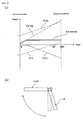
- the liquid crystal display device 1 is in a substantially flat orientation when in a stored position 1A, and is in a substantially perpendicular orientation when in an opned position 1B, as shown in FIG. 5(b) . Therefore, a torque T(1) based on the weight that turns the liquid crystal display device 1 in the opening direction is at a maximum in a closed state, is reduced as the display device is turned toward the deployed position 1B, and is at a minimum when the device is in the perpendicular orientation, as shown in FIG. 5(a) .
- the spiral spring will have the least number of coils (state of the initial number of coils) when the liquid crystal display device 1 is closed; therefore, the returning force T(18) of the spiral spring will be at a minimum.
- the number of coils will be at a maximum when the liquid crystal display device 1 reaches the deployed position 1B; therefore, the returning force T(18) will also be at a maximum.
- the returning force T(18) in the state of the initial number of coils must exceed the torque T(1) in the opening direction created by the weight of the liquid crystal display device 1 when in a closed state in order for the liquid crystal display device 1 to be returned to the stored position 1A by the spiral spring.
- Braking mechanisms able to be used include hydraulic dampers, electromagnetic brakes, and gear dampers in which the braking force increases in proportion to the speed.
- gear dampers comprise a plurality of gears, are configured so that frictional force increases with centrifugal force, involve a complex mechanism, and have poor reliability.
- problems are also presented in that hydraulic dampers must be of a large size in order to maintain a prescribed braking force and are not suitable for being incorporated in retracting devices for liquid crystal display devices and the like.
- US 1 417 173 A discloses a door-operating device comprising a door and a shaft operatively connected with the door for moving the same, a motor, power transmitting means arranged between the motor and the shaft, a spring connected to said shaft and adapted to wind during the opening of the door by said motor, a one-way acting clutch mechanism between the spring and said means for permitting the door to be operated independently of the motor, and an automatic device operatively connected with said means in order to limit the speed with which the door is moved by the motor and by the spring.
- US 4 675 938 A discloses a retraction device for automatically closing a panel, such as a door or window, after the panel has been opened.
- the retraction device includes a drum, a coiled spring power assembly for driving the drum, a centrifugal brake for controlling the power assembly and the drum to eliminate slamming of the panel during closing, and a gear train transmission assembly to connect the power assembly and the centrifugal brake.
- the drum is a spool which carries a cable to connect the panel to the retraction device.
- the drum has a rim which frictionally engages a frame supporting the panel.
- the centrifugal brake is adjustable to take into account a wide range of panel sizes and frictional conditions.
- a one-way clutch mechanism is coupled between the power assembly and the brake to actuate the brake only when the panel is being retracted.
- This clutch mechanism is formed by two members, each of which is integrally molded of plastic.
- An object of the present invention is to provide a brake-equipped retracting device for a liquid crystal display device and other retractable members, which comprises a braking mechanism having a simple structure and high reliability.
- a brake-equipped retracting device for a retractable member characterized in comprising:
- a cord is wound around the rotating member for transmitting the rotational force of the motor, and the tensile force of the cord is increased or decreased in relation to the opening and closing of the retractable member. Therefore, a retracting device can be realized that comprises a braking mechanism that is extremely simple but has a higher reliability and lower cost than when a gear damper or another existing braking mechanism is used.
- the rotating member will rotate at a high rate and the retractable member will move quickly toward the stored position; however, the rotation-regulating mechanism will operate when the rotating member rotates at a high rate, and the rotation of the rotating member will be forcibly halted. Therefore, even if the cord breaks or another malfunction occurs, the retractable member can reliably be prevented from closing too quickly toward the stored position, and a highly safe retracting device can therefore be realized.
- the rotation-regulating mechanism may function during the closing operation of the retractable member.
- the rotational force of the motor may be transmitted to the rotating member via an electromagnetic clutch, and the electromagnetic clutch may be disengaged when the retractable member is returned to the stored position.
- the electromagnetic clutch, the rotation-regulating mechanism, and a slip clutch are preferably connected in the stated order to a rotational force transmission channel between the motor and the rotating member, and impact force is alleviated by allowing the slip clutch to slip.
- the rotation-regulating mechanism may have a configuration that comprises a fixed member and a slip member attached to the fixed member in a state allowing the slip member to slip when acted upon by a force greater than or equal to a prescribed force, and a fixed-side engagement part is formed on the slip member.
- the rotational movement of the rotating member is transmitted toward the retractable member via a link member that can turn about the rotating member between a rotational position that corresponds to the stored position and a rotational position that corresponds to the deployed position.
- one end of the cord may be fixed directly or via a braking spring member in order to increase or decrease the tensile force of the cord with the opening and closing action of the retractable member while the other end of the cord is connected to the link member either directly or via a braking spring member.
- the degree of elastic deformation of the braking spring member will increase, the pulling force acting upon the cord will increase, and the rotation-restraining force of the rotating member will increase. In other words, the braking force will increase. Conversely, if the cord slackens, the degree of elastic deformation of the braking spring member will decrease, the pulling force acting upon the cord will decrease, and the rotation-restraining force (braking force) of the rotating member will decrease.
- a central portion of the cord may be wound around a brake drum that is subjected to a rotation-restraining force by the braking spring member instead of having the braking spring member connected to an end of the cord.
- a central portion of the cord may be wound around a tensile force-adjustment drum in order to adjust the tensile force acting upon the rotating member by the braking spring member or to adjust the amount of tensile force or the amount of slack of the cord accompanying the turning of the link member.
- the cord is wound around the rotating member that transmits the rotational force of the motor, and the tensile force of the rope is increased and reduced in association with the opening and closing of the retractable member.
- a retracting device comprising a braking mechanism that is extremely simple, but also highly reliable and low in cost, can therefore be realized.
- the retracting device comprises a mechanical rotation-regulating mechanism that forcibly halts the rotation of the rotating member using centrifugal force. Therefore, if the cord breaks, the rotation-regulating mechanism functions as a backup brake, and the retractable member will not slam shut. An extremely safe retracting device can therefore be realized.
- a brake-equipped retracting device of a liquid crystal display device in which the present invention is used and which is provided to the ceiling of a passenger cabin of an airplane shall be described herein below with reference to the drawings.
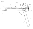
- FIG. 1 is a diagram of an overall configuration showing a brake-equipped retracting device of a liquid crystal display device.
- a liquid crystal display device 1 can be turned from a flat stored position 1A, indicated by the solid line, in which the device is stored in the ceiling 2 of the passenger cabin of an airplane, to an deployed position 1B, indicated by the imaginary line, in which the device is opened downward in an amount that is substantially 105°.
- a brake-equipped retracting device 3 of the liquid crystal display device 1 comprises a main body 4 of the mechanism, and a link mechanism 6 for converting the rotational movement of the main body 4 of the mechanism into a movement for retracting the liquid crystal display device 1 (a turning movement) about a turning central axis 5.
- the link mechanism 6 comprises, for example, a drive-side link 7 that is connected to the main body 4 of the mechanism side, a driven-side link 8 that is connected to the turning central axis 5 side of the liquid crystal display device 1, and an intermediate link 9 that bends at a slight angle and is connected between the drive-side link 7 and the driven-side link 8.
- the liquid crystal display device 1 is in the stored position 1 A when the drive-side link 7 is in a first position 7A indicated by the solid line.
- the liquid crystal display device 1 reaches the deployed position 1B when the drive-side link 7 is turned to a second position 7B indicated by the imaginary line.
- a screen 1a of the liquid crystal display device 1 can be viewed from a seat when the liquid crystal display device 1 reaches the deployed position 1B.
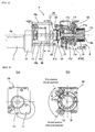
- FIG. 2 is a diagram showing the main body 4 of the mechanism of the brake-equipped retracting device 3 and is a contour block diagram of a case in which the device has been cut along the central axis line.
- FIGS. 3(a) and 3(b) are an end view showing the rear end of the main body 4 of the mechanism, and an end view showing the front end of the main body 4 of the mechanism.
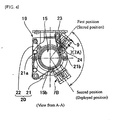
- FIG. 4 is a perspective view as seen from the direction of the arrow A of FIG. 2 .
- the main body 4 of the mechanism has a motor 11 on the rear end thereof, and the rotation of the motor 11 is transmitted via a row of reduction gears 12 to an input side of a one-way clutch 13 that is arranged along a central axis line 4a of the mechanism in a coaxial fashion.
- the one-way clutch 13, an electromagnetic clutch 14, a rotation-regulating mechanism 50, and a slip clutch 15 are arranged in the stated order in a coaxial fashion along the central axis line 4a of the mechanism from the rear end to the front end.
- the output side of the slip clutch 15 is connected to a rear end of an input shaft 17a of a coaxially arranged planetary gear reducer 17.
- a front end part 17b of the input shaft 17a protrudes to a prescribed length from the end face of the front end of the planetary gear reducer 17.
- An inner end of a spiral spring 18 that is coiled about the leading end 17b in a spiral shape is connected to the front end part 17b.
- An outer end of the spiral spring 18 is fixed to a cup-shaped case 18a that is fixed to a side of a mechanism frame 19.
- the planetary gear reducer 17 comprises a sun gear 17c that is coaxially fixed to the input shaft 17a, an internal gear 17d that coaxially surrounds the sun gear 17c, and a plurality of planetary gears 17e that are disposed between the sun gear 17c and the internal gear 17d and that mesh with both gears.
- the planetary gears 17e are rotatably supported by a planetary carrier 17f.
- the planetary carrier 17f is fixed to the mechanism frame 19, and the internal gear 17d is rotatably supported by a front and rear pair of ball bearings.
- the internal gear 17d rotates counter to the input shaft 17a, and outputs a reduced-speed rotation.
- the drive-side link 7 of the link mechanism 6 is fixed to the outer peripheral surface of the internal gear 17d.
- the drive-side link 7 extends parallel to the central axis line 4a of the mechanism toward the front end, and one end of the intermediate link 9 is connected to the front end.
- the liquid crystal display device 1 is in the stored position 1 A when the drive-side link 7 is in the first position 7A indicated by the solid line; and the liquid crystal display device 1 reaches the deployed position 1B when the drive-side link 7 reaches the second position 7B indicated by the imaginary line.
- the rotational force of the motor 11 is transmitted to the input shaft 17a of the planetary gear reducer 17, and the internal gear 17d, which is an output element of the rotational force, is rotated at a reduced rate.
- the rotational movement is converted to a movement that turns the liquid crystal display device 1 via the link mechanism 6, and the liquid crystal display device 1 begins to move toward the deployed position 1B.
- the spiral spring 18 is additionally caused to twist by the rotation of the input shaft 17a.
- the motor 11 stops, and the liquid crystal display device 1 is kept in the deployed position 1B.
- the one-way clutch 13 and the slip clutch 15 are provided to prevent returning and to prevent overloading, respectively.
- the electromagnetic clutch 14 is disengaged and the connection between the motor 11 and the reducer 17 is severed.
- the input shaft 17a of the reducer 17 is connected to the spiral spring 18 and therefore begins to be rotated in reverse by the elastic returning force of the spiral spring 18 that is wound up when the liquid crystal display device 1 is opened.
- the internal gear 17d of the reducer 17 rotates in the opposite direction at a reduced rate, the drive-side link 7 that is attached to the internal gear 17d is turned toward the first position 7A, and the liquid crystal display device 1 therefore also begins to move gradually toward the stored position 1A.
- the liquid crystal display device 1 After the liquid crystal display device 1 has returned to the stored position 1A, the liquid crystal display device 1 is kept in the position by the elastic force of the spiral spring 18.
- the torque T(1) that causes the liquid crystal display device 1 to rotate in the spread direction (opening direction) based on the weight of the liquid crystal display device 1 is at a maximum when the liquid crystal display device 1 is in a flat orientation in the closed state, and is zero when the liquid crystal display device 1 is in a perpendicular orientation (a 90°-rotated position) just before the stored position 1B.
- a low torque is generated in the opposite direction when the device is in the deployed position 1B.
- the returning torque that is needed to return the liquid crystal display device 1 from the deployed position to the stored position against the torque T(1) created by the weight increases toward the stored position 1A, and is ideally at a maximum in the stored position 1A.
- the liquid crystal display device 1 can thereby be returned to the stored position 1A according to a substantially constant torque.
- the retuning torque T(18) produced by the spiral spring 18 is at a maximum in the deployed position 1B, gradually decreases toward the stored position 1A, and is at a minimum in the stored position 1A.
- the composite returning torque T(1 + 18) created by the weight and the spiral spring is extremely high in the deployed position 1B. This is undesirable in that, when the liquid crystal display device 1 is closed, the liquid crystal display device 1 quickly turns from the deployed position 1B toward the stored position 1 A.
- the retracting device 1 comprises a braking mechanism 20 for applying a brake to the turning.
- the braking mechanism 20 of the present example comprises a rope 21 made of Teflon (registered trademark) and a braking coil spring 22.
- a rear end 21 a of the rope 21 is connected to the braking coil spring 22, one end of which is connected to the mechanism frame 19.
- the rope 21 is drawn in the elongation direction of the braking coil spring 22, crossed over a pulley 23 that is attached to the mechanism frame 19, and subsequently wound multiple times around an outer peripheral surface 15b of a cylindrical case of the slip clutch 15 to which the input shaft 17a is connected.
- the rope 21 After being drawn from the outer peripheral surface 15b and crossed over a pulley 23, the rope 21 is further drawn in the opposite direction, and the distal end 21 b of the rope 21 is connected to a distal end of a connecting bar 24 that is fixed to the drive-side link 7.
- the drive-side link 7 When the drive-side link 7 is in the first position (i.e., when the liquid crystal display device 1 is in the stored position 1 A), the rope 21 will be maximally slack. Therefore, the braking coil spring 22 will be maximally compressed.
- the drive-side link 7 is turned toward the second position, the rope 21 is accordingly pulled, the braking coil spring 22 gradually elongates, and the pulling force of the rope 21 increases. As a result, the rotation-restraining force (braking force) against the cylindrical case 15a of the slip clutch 15 around which the rope 21 is wound also increases.
- the braking force against the slip clutch 15 produced by the rope 21 is at a maximum when the drive-side link 7 has reached the second position (i.e., when the liquid crystal display device 1 has reached the deployed position 1B), as indicated by the curved line T(21) of FIG. 5(a) . Therefore, when the liquid crystal display device 1 is returned from the deployed position 1B to the stored position 1A, the input shaft 17a of the reducer is subjected to a large braking force from the slip clutch 15. The rotating input shaft 17a of the reducer is thus subjected to a braking force by the elastic returning force of the spiral spring 18, and the rotation rate of the input shaft 17a is reduced. In other words, a substantially constant torque acts as the returning torque, and the liquid crystal display device 1 is turned from the deployed position to the stored position at a substantially constant rate, as indicated by the curved line T (1 + 18 + 21) in FIG. 5(a) .
- the elastic returning force T(18) of the spiral spring 18 decreases because the spiral spring 18 gradually unwinds as the liquid crystal display device 1 approaches the stored position 1A.
- the pull of the rope 21 gradually weakens as the liquid crystal display device 1 approaches the stored position 1A, and the braking force T(21) produced by the pulling force of the rope 21 therefore also gradually decreases. Therefore, when the liquid crystal display device 1 is to be stored, a substantially equal returning torque (1 + 18 + 21) acts on the device, and the liquid crystal display device 1 returns to the stored position 1A at a substantially constant rate.
- the rope 21 that is pulled by the coil spring 22 is wound around the slip clutch 15 that is connected to the input shaft 17a of the reducer; the braking force that is at a maximum when the liquid crystal display device 1 is in the deployed position is applied to the input shaft 17a of the reducer; the rope 21 slackens as the liquid crystal display device 1 is oriented from the deployed position to the stored position; and the braking force is reduced.
- Adopting a configuration that is extremely simple and low in cost therefore allows a prescribed braking force to be reliably applied, and a highly reliable retracting device to be realized.
- FIGS. 6(a), 6(b) , and 6(c) are views showing a main body 4 of the mechanism having the braking mechanism 20A.
- FIG. 6(a) is a contour block diagram of a case in which the main body is cut along the central axis line
- FIG. 6(b) is a perspective view as seen from the direction of the arrow A
- FIG. 6(c) is a descriptive view of the braking mechanism.
- the basic configuration of the main body of the mechanism is the same as that of the main body 4 of the mechanism described above. Therefore, the same numeric symbols are applied to the corresponding regions, and descriptions thereof have been omitted.
- the braking mechanism 20A of the main body of the mechanism of the present example comprises a Teflon rope 31, a braking force adjustment drum 33 that comprises a braking coil spring 32, and a tensile force adjustment drum 34.
- a rear end 31a of the rope 31 is fixed to a mechanism frame 19, drawn therefrom, wound around an outer peripheral surface 15b of a slip clutch 15, and subsequently wound multiple times around the braking adjustment drum 33.
- the rope 31 is then drawn therefrom, wound around a small-diameter drum 34a and a large-diameter drum 34b of the tensile force adjustment drum 34, drawn across a pulley 35, and subsequently connected to a connecting bar 36 on the drive-side link 7.
- the braking adjustment drum 33 comprises a spindle 33a fixed to the mechanism frame 19 and a drum main body 33b rotatably supported by a distal end of the spindle 33a.
- the drum main body 33b is fixed to the distal end of the braking coil spring 32 that is disposed surrounding the spindle 33.
- the rear end of the braking coil spring 32 is fixed to the spindle 33a or the mechanism frame 19.
- the braking mechanism 20A of the present example functions in the same manner as the braking mechanism 20 of the main body 4 of the mechanism described above, and the liquid crystal display device 1 can be returned from the deployed position 1B to the stored position 1 A at a substantially uniform rate.
- an intermediate portion of the rope 31 is wound around the tensile force adjustment drum 34.
- the degree to which the rope 31 is pulled or made slack, and the tensile force generated in conjunction with the turning of the drive-side link 7, can be adjusted by changing the diameter of, e.g., the large-diameter drum 34b of the tensile force adjustment drum 34.
- the braking force can therefore readily be adjusted.
- the rotation-regulating mechanism 50 that is connected between the slip clutch 15 and the one-way clutch 13 functions as a backup brake if the rope 21 slips off or breaks when the liquid crystal display device 1 returns from the deployed position 1B to the stored position 1A. If the rope 21 slips off or breaks, a braking force will not be produced by the rope 21, and a hazard is therefore presented in that the liquid crystal display device 1 will slam shut from the deployed position 1B to the stored position 1A. If the slip clutch 15 rotates quickly, the rotation of the slip clutch 15 will be forcibly halted without the use of a braking force by the action of the rotation-regulating mechanism 50 that is connected to the slip clutch, and the movement of the liquid crystal display device 1 will be stopped.
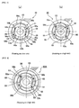
- FIG. 7 is a descriptive view showing the configuration of the rotation-regulating mechanism 50 of the present example.
- the rotation-regulating mechanism 50 comprises a rotating shaft 51 coaxially connected to the slip clutch 15, and a rotating plate 52 is concentrically fixed to the rotating shaft 51 so as to rotate integrally.
- An annular boss 52a is formed on a central portion of the rotating plate 52, and two centrifugal grips 53, 53 are attached to end faces of the rotating plate 52 to be positioned on the outer peripheral side of the boss 52a at both ends in the diametric direction.
- the centrifugal grip 53 is an arched plate of fixed width spanning a substantially 90° angle.
- the grip can be turned in the radial direction along an end face of the rotating plate 52 about a spindle 54 that is attached to one end 53a of the centrifugal grip 53.
- a coil spring 55 (restraining spring member) bridges the gap between the other end 53b of the centrifugal grip 53 and the rotating plate 52.
- the centrifugal grip 53 is normally pulled toward the inside in the radial direction by the springing force of the coil spring 55 and is pressed to a circular outer peripheral end face 52b of the boss 52a of the rotating plate.
- annular fixed casing 56 that concentrically surrounds the rotating plate 52 is disposed on the outside of the rotating plate 52.
- the annular fixed casing 56 is a stationary side member that is fixed to connecting rods 19a, 19b (see FIG. 2 ) attached to the mechanism frame 19 of the main body 4 of the mechanism.
- Curved incisions 56a are formed on the inner peripheral surface of the annular fixed casing 56 at 90° angular intervals so that the centrifugal grip 53 can turn toward the outer peripheral side by a prescribed amount.
- the incisions 56a become deeper toward one side in the circumferential direction, and engagement notch surfaces 56b that extend in a radial direction are formed between the incisions 56a.
- a brake will not be applied if the braking rope 21 slips off, breaks, or otherwise malfunctions when the liquid crystal display device 1 is closed from the deployed position 1B to the stored position 1A, and the rotating shaft 51 will therefore rotate at a high rate. If the rotating shaft 51 rotates at a high rate, the centrifugal force acting upon the centrifugal grips 53 will exceed the springing force of the coiled spring 55, and the centrifugal grips 53 will turn about the spindle 54 toward the outer peripheral side. As a result, the distal end faces 53c of the centrifugal grips 53 will strike the engagement notch surfaces 56b of the fixed casing 56, and the rotation of the rotating shaft 51 will be forcibly halted, as shown in FIG. 7(b) . The liquid crystal display device 1 can thereby be prevented from slamming shut even in cases such as when the rope 21 breaks, and safety can be maintained.
- a rotation-regulating mechanism 50A may be used in which a slip casing 57 is attached to the fixed casing 56, and an engagement notch surface 56c is formed on the inner peripheral surface of the slip casing 57, as shown in FIG. 8 .
- the slip casing 57 is attached to the fixed casing 56 via a slip element 58, and can slip and rotate against the fixed casing 56 when a torque that is equal to or greater than a prescribed amount is applied.
- the slip casing 57 slips and the impact force resulting from the centrifugal grips 53 striking the engagement notch surfaces 56b is alleviated.
- the slip clutch 15 can also be dispensed with.
- the rope 21 may be wound around a rotating member that is connected between the input shaft 17a of the planetary gear reducer 17 and the rotation-regulating mechanism 50A.
- the liquid crystal display device 1 can be stored by being manually pushed in the closing direction when the rotation-regulating mechanism 50A operates and the liquid crystal display device 1 stops in an intermediate position.
- the rotation-regulation mechanisms 50, 50A shown in FIGS. 7 and 8 function when an abnormality occurs while the liquid crystal display device 1 is being closed.
- a centrifugal grip that is moved by the effect of a centrifugal force when the rotating shaft 51 rotates in the opposite direction, and an engagement notch surface formed in a position whereby the centrifugal grip can be engaged when moving, may be provided to allow the liquid crystal display device 1 to be forcibly halted when an abnormality occurs while the liquid crystal display device 1 is being opened (i.e., opened from the stored position to the deployed position).
- the present invention can also be used in a brake-equipped retracting device for retracting a retractable member of an object other than a liquid crystal display device disposed on the ceiling of an airplane.
- a Teflon rope was used as the cord for generating the braking force in the above-described example.
- a rope or cord composed of a different material or a wire can also be used.
- the one-way clutch when the one-way clutch is disposed on the slip clutch 15 in a concentric fashion, the following effects can be obtained. Specifically, a reduction can be achieved in the load on the motor caused by the braking force when the liquid crystal display device 1 is deployed, and looseness due to the unwinding of the cord for generating the braking force can be prevented.
Landscapes
- Engineering & Computer Science (AREA)
- General Engineering & Computer Science (AREA)
- Mechanical Engineering (AREA)
- Devices For Indicating Variable Information By Combining Individual Elements (AREA)
- Braking Arrangements (AREA)
- Curtains And Furnishings For Windows Or Doors (AREA)
- Fixing For Electrophotography (AREA)
- Operating, Guiding And Securing Of Roll- Type Closing Members (AREA)
Claims (8)
- Mit einer Bremse ausgestattete Rückziehvorrichtung (3) für ein rückziehbares Element (1) aufweisend:einen Motor (11) zum Erzeugen einer Rotationskraft, um ein rückziehbares Element (1) aus einer Parkposition (1A) in eine Arbeitsposition (1B) zu öffnen;ein Rückziehfederelement (18), um das rückziehbare Element (1) durch eine elastische Rückstellkraft, die durch seine elastische Deformation erzeugt wird, aus der Arbeitsposition in die Parkposition (1A) zurückzuziehen, wobei das Ausmaß der elastischen Deformation bei einer Öffnungsaktion des rückziehbaren Elements (1) zunimmt;ein Rotationselement (51), um eine Rotationskraft des Motors (11) und eine elastische Rückstellkraft des Rückstellfederelements (18) auf das rückziehbare Element (1) zu übertragen; undeinen Rotationsregulationsmechanismus (50; 50A), um die Rotation des Rotationselements (51) zwangsweise zu stoppen, wenn die Drehzahl des Rotationselements (51) eine vorgeschriebene Drehzahl überschreitet, wobeider Rotationsregulationsmechanismus (50; 50A) ein Zentrifugaleingreifelement (53), das durch eine Zentrifugalkraft bewegt werden kann, die in Verbindung mit einer Rotation des Rotationselements (51) erzeugt wird; ein begrenzendes Federelement (55), um die Bewegung des Zentrifugaleingreifelement (53) zu beschränken; und einen stationären Eingriffsbereich (56b) hat, in den das Zentrifugaleingreifelement (53), das durch die Zentrifugalkraft in einem Ausmaß, das gleich oder größer als ein vorgegebenes Ausmaß ist, bewegt worden ist, eingreifen kann;dadurch gekennzeichnet, dass die mit einer Bremse ausgestattete Rückziehvorrichtung (3) zusätzlicheinen Gurt (21; 31) aufweist, der um das Rotationselement (51) gewunden ist, um die Rotation des Rotationselements (51) zu beschränken; wobeider Gurt (21; 31) so angepasst ist, dass bei einer Öffnungsaktion des rückziehbaren Elements (31) die Spannkraft und die auf das Rotationselement (51) wirkende, die Rotation beschränkende Kraft zunehmen, wogegen bei einer Aktion des Schließens des rückziehbaren Elements (1) die Spannkraft und die auf das Rotationselement (51) wirkende und die Rotation beschränkende Kraft abnehmen.
- Mit einer Bremse ausgestattete Rückziehvorrichtung (3) für ein rückziehbares Element (1) nach Anspruch 1, dadurch gekennzeichnet, dass der Rotationsregulationsmechanismus (50; 50A) im Betrieb ist, während sich das rückziehbare Element (1) schließt.
- Mit einer Bremse ausgestattete Rückziehvorrichtung (3) für ein rückziehbares Element (1) nach Anspruch 1 oder 2, dadurch gekennzeichnet, dass eine elektromagnetische Kupplung (14), der Rotationsregulationsmechanismus (50; 50A) und eine Gleitkupplung (50) in einer festgelegten Reihenfolge mit einem Rotationskraftübertragungskanal zwischen dem Motor (11) und dem Rotationselement (51) verbunden sind; und
die elektromagnetische Kupplung (14) in einen gelösten Zustand geschaltet wird, wenn das rückziehbare Element (1) in die Parkposition (1A) zurückgeführt wird. - Mit einer Bremse ausgestattete Rückziehvorrichtung (3) für ein rückziehbares Element (1) nach Anspruch 1 oder 2', dadurch gekennzeichnet, dass der Rotationsregulationsmechanismus (50; 50A) aufweist:ein fixiertes Element (56); undein Gleitelement (57), das so an dem fixierten Element (56) angebracht ist, dass es in der Lage ist, zu gleiten, wenn eine Kraft aufgebracht wird, die größer oder gleich einer vorgegebenen Kraft ist;wobei der stationäre Eingriffsbereich (56) auf dem Gleitelement (57) ausgebildet ist.
- Mit einer Bremse ausgestattete Rückziehvorrichtung (3) für ein rückziehbares Element (1) nach Anspruch 4, dadurch gekennzeichnet, dass eine elektromagnetische Kupplung (14) und der Rotationsregulationsmechanismus (50; 50A) in einer vorgegebenen Reihenfolge mit einem Rotationskraftübertragungskanal zwischen dem Motor (11) und dem Rotationselement (51) verbunden sind; und
die elektromagnetische Kupplung (14) in einen gelösten Zustand geschaltet wird, wenn das rückziehbare Element (1) in die Parkposition (1A) zurückgeführt wird. - Mit einer Bremse ausgestattete Rückziehvorrichtung (3) für ein rückziehbares Element (1) nach einem der Ansprüche 1 bis 5, dadurch gekennzeichnet, dass sie ein Verbindungselement (24) aufweist, das sich zwischen einer Rotationsposition (7A), die der Parkposition (1A) entspricht und einer Rotationsposition (7B), die der Arbeitsposition (1B) entspricht, um das Rotationselement (51) drehen kann, um eine Rotationsbewegung des Rotationselements (51) auf das rückziehbare Element (1) zu übertragen; wobei
ein Ende (21a) des Gurtes (21) entweder direkt oder über ein Federelement mit einer vorgegebenen Stelle verbunden und daran befestigt ist; und
das andere Ende (21b) des Gurtes (21) entweder direkt oder über ein Federelement mit dem Verbindungselement (24) verbunden ist. - Mit einer Bremse ausgestattete Rückziehvorrichtung (3) für ein rückziehbares Element (1) nach einem der Ansprüche 1 bis 5, dadurch gekennzeichnet, dass sie ein Verbindungselement (36), das zwischen einer Rotationsposition (7A), die der Parkposition (1A) entspricht, und einer Rotationsposition (7B), die der Arbeitsposition (1B) entspricht, um das Rotationselement (51) gedreht werden kann, um eine Rotationsbewegung des Rotationselements (51) auf das rückziehbare Element (1) zu übertragen; und
eine Bremstrommel (33) aufweist, die durch das Federelement (32) einer rotationsbeschränkenden Kraft ausgesetzt ist; wobei
ein Ende (31a) des Gurtes (31) mit einer vorgegebenen Stelle verbunden und daran befestigt ist, während das andere Ende (31b) des Gurtes (31) mit dem Verbindungselement (36) verbunden ist; und
ein Bereich des Gurtes (31) um die Bremstrommel (33) gewunden ist. - Mit einer Bremse ausgestattete Rückziehvorrichtung (3) für ein rückziehbares Element (1) nach einem der Ansprüche 6 oder 7, wobei ein mittlerer Bereich des Gurtes (31) um eine Spannkraft-Anpassungstrommel gewunden ist.
Applications Claiming Priority (2)
| Application Number | Priority Date | Filing Date | Title |
|---|---|---|---|
| JP2005190555 | 2005-06-29 | ||
| PCT/JP2006/309929 WO2007000857A1 (ja) | 2005-06-29 | 2006-05-18 | 開閉部材のブレーキ付き開閉装置 |
Publications (3)
| Publication Number | Publication Date |
|---|---|
| EP1898384A1 EP1898384A1 (de) | 2008-03-12 |
| EP1898384A4 EP1898384A4 (de) | 2012-04-04 |
| EP1898384B1 true EP1898384B1 (de) | 2013-03-20 |
Family
ID=37595114
Family Applications (1)
| Application Number | Title | Priority Date | Filing Date |
|---|---|---|---|
| EP06756344A Expired - Lifetime EP1898384B1 (de) | 2005-06-29 | 2006-05-18 | Vorrichtung mit einer bremse, zum öffnen und schliessen eines öffnungs-/schliesselements |
Country Status (6)
| Country | Link |
|---|---|
| US (1) | US7686141B2 (de) |
| EP (1) | EP1898384B1 (de) |
| JP (1) | JP4568288B2 (de) |
| CN (1) | CN101091199B (de) |
| TW (1) | TW200716883A (de) |
| WO (1) | WO2007000857A1 (de) |
Families Citing this family (11)
| Publication number | Priority date | Publication date | Assignee | Title |
|---|---|---|---|---|
| US7717446B2 (en) * | 2006-11-21 | 2010-05-18 | Pt Motion Works, Inc. | Self-propelled vehicle propelled by an elliptical drive train |
| CN102537118B (zh) * | 2010-12-14 | 2015-02-11 | 李占军 | 一种离合器 |
| US20130286570A1 (en) * | 2011-06-23 | 2013-10-31 | Panasonic Corporation | Display holding mechanism and openable display apparatus |
| CN103016927B (zh) | 2012-12-12 | 2014-12-24 | 中电科航空电子有限公司 | 一种用于液晶显示器展开及收回的装置及其控制方法 |
| CN110838781B (zh) * | 2014-08-18 | 2021-12-21 | 涡流有限合伙公司 | 闩锁设备 |
| DE102016214968A1 (de) | 2016-08-11 | 2018-02-15 | Continental Teves Ag & Co. Ohg | Eine Bremseinrichtung aufweisendes Differentialgetriebe |
| CN108298092A (zh) * | 2018-03-22 | 2018-07-20 | 北京安达维尔民用航空技术有限公司 | 一种显示设备的旋转调节装置 |
| CN109479846A (zh) * | 2018-12-28 | 2019-03-19 | 王治军 | 一种鱼钩的收纳机构 |
| CN112093567A (zh) * | 2020-10-21 | 2020-12-18 | 诸暨市澳速机械设计工作室 | 基于薄膜匀速放卷实现多级换料警报无极切换的预警设备 |
| CN113470533B (zh) * | 2021-07-09 | 2022-12-20 | 夏聆(浙江)视觉科技有限公司 | 一种教育信息资源数字化展示装置 |
| US12528440B2 (en) * | 2023-10-30 | 2026-01-20 | GM Global Technology Operations LLC | Seatbelt system |
Family Cites Families (16)
| Publication number | Priority date | Publication date | Assignee | Title |
|---|---|---|---|---|
| US1417173A (en) * | 1920-06-22 | 1922-05-23 | Jacob R Kaiserman | Electrical door-operating device |
| GB500209A (en) * | 1936-08-08 | 1939-02-06 | Air Equipment | Improvements in winches, more particularly intended for aircraft |
| US3795985A (en) * | 1970-09-21 | 1974-03-12 | Hitachi Ltd | Brake for centrifugal extractor |
| SE390131B (sv) * | 1971-04-13 | 1976-12-06 | Partner Ab | Bromsanordning vid motorsagar |
| DE2733771C2 (de) * | 1977-07-27 | 1983-02-17 | Licentia Patent-Verwaltungs-Gmbh, 6000 Frankfurt | Einrichtung zum Verzögern der Bewegung eines Kassettenfachdeckels |
| US4675938A (en) * | 1985-11-06 | 1987-06-30 | Bundschuh Robert L | Retraction device for doors or windows |
| JP3008437B2 (ja) * | 1990-04-20 | 2000-02-14 | 松下電器産業株式会社 | 表示装置 |
| US5203392A (en) * | 1992-03-30 | 1993-04-20 | Anchuan Corporation | Mechanism for controlling the raising and lowering of a door |
| DE4330850A1 (de) * | 1993-09-11 | 1995-03-16 | Stihl Maschf Andreas | Mechanisches Zweikreis-Bremssystem |
| JPH08303496A (ja) * | 1995-04-28 | 1996-11-19 | Chuo Spring Co Ltd | 遠心式ブレーキおよび窓開閉装置 |
| DE19618640C2 (de) * | 1995-05-11 | 2001-02-15 | Stihl Maschf Andreas | Motorkettensäge mit einer Kettenbremseinrichtung |
| US5680911A (en) * | 1996-03-05 | 1997-10-28 | Wang; Chiou Nan | Elector emergency device |
| JP3353141B2 (ja) * | 1998-11-24 | 2002-12-03 | ミネベア株式会社 | 乗物用映像モニタの格納装置 |
| JP2000217050A (ja) * | 1999-01-25 | 2000-08-04 | Jamco Corp | 液晶モニタ―装置 |
| US6123134A (en) * | 1999-04-07 | 2000-09-26 | Clopay Building Products Company, Inc. | Method and apparatus for regulating the closing speed of a rolling fire door |
| JP4614721B2 (ja) * | 2004-09-22 | 2011-01-19 | 株式会社ハーモニック・エイディ | 開閉部材のブレーキ付き開閉機構 |
-
2006
- 2006-05-18 US US11/628,422 patent/US7686141B2/en active Active
- 2006-05-18 JP JP2006548021A patent/JP4568288B2/ja not_active Expired - Lifetime
- 2006-05-18 WO PCT/JP2006/309929 patent/WO2007000857A1/ja not_active Ceased
- 2006-05-18 CN CN200680000396.3A patent/CN101091199B/zh not_active Expired - Lifetime
- 2006-05-18 EP EP06756344A patent/EP1898384B1/de not_active Expired - Lifetime
- 2006-06-01 TW TW095119405A patent/TW200716883A/zh unknown
Also Published As
| Publication number | Publication date |
|---|---|
| EP1898384A4 (de) | 2012-04-04 |
| WO2007000857A1 (ja) | 2007-01-04 |
| JP4568288B2 (ja) | 2010-10-27 |
| CN101091199B (zh) | 2012-04-04 |
| EP1898384A1 (de) | 2008-03-12 |
| TW200716883A (en) | 2007-05-01 |
| US7686141B2 (en) | 2010-03-30 |
| JPWO2007000857A1 (ja) | 2009-01-22 |
| US20080283650A1 (en) | 2008-11-20 |
| CN101091199A (zh) | 2007-12-19 |
Similar Documents
| Publication | Publication Date | Title |
|---|---|---|
| US9574389B2 (en) | Line belt driven retrofittable door opener, system, and method of retrofitting thereof | |
| JP4264139B2 (ja) | 線形アクチュエータ | |
| US5799716A (en) | Electric-powered shutter apparatus for a building opening | |
| US8931541B2 (en) | Motorized drive unit assembly for a shade system | |
| EP1276951B1 (de) | Verriegelungsvorrichtung von einem deckenlauftor | |
| US20200018110A1 (en) | Overhead door lift assembly | |
| US7686141B2 (en) | Brake-equipped retracting device for retractable member | |
| EP1775410A2 (de) | Verriegelungsvorrichtung eines Deckenlauftors | |
| EP1640267B1 (de) | Rückziehmechanismus für ein rückziehbares Element, mit einer Bremse ausgestattet | |
| US20130269881A1 (en) | Door release mechanism | |
| US10760657B2 (en) | Apparatus utilizing planetary gearset coupled to a constant torsion spring | |
| HUE033083T2 (en) | Adjusting drive with at least one adjusting lever | |
| US11441347B2 (en) | Mechanism for opening and closing an overhead door including one way bearing | |
| CN116133908B (zh) | 安全带卷收器 | |
| US4428542A (en) | Wire-driving device for window regulator | |
| US6918211B2 (en) | Door closing device | |
| US6059008A (en) | Braking device for shutter for building | |
| JPH11101077A (ja) | シャッター | |
| JP2019108678A (ja) | 扉開閉装置 | |
| JP3795492B2 (ja) | 引戸 | |
| JP4294527B2 (ja) | 出入口シート開閉機におけるシート昇降調節装置 | |
| EP4123117A1 (de) | Notbedienungseinheit für rollläden | |
| JPH074162A (ja) | シャッタ、主にローラシャッタのための駆動装置 | |
| US20260002399A1 (en) | Cable drum cable tensioner and methods in a movable barrier system | |
| JPS6364580B2 (de) |
Legal Events
| Date | Code | Title | Description |
|---|---|---|---|
| PUAI | Public reference made under article 153(3) epc to a published international application that has entered the european phase |
Free format text: ORIGINAL CODE: 0009012 |
|
| 17P | Request for examination filed |
Effective date: 20061205 |
|
| AK | Designated contracting states |
Kind code of ref document: A1 Designated state(s): DE FR |
|
| RBV | Designated contracting states (corrected) |
Designated state(s): DE FR |
|
| DAX | Request for extension of the european patent (deleted) | ||
| RAP1 | Party data changed (applicant data changed or rights of an application transferred) |
Owner name: HARMONIC AD, INC. Owner name: PANASONIC CORPORATION |
|
| A4 | Supplementary search report drawn up and despatched |
Effective date: 20120307 |
|
| RIC1 | Information provided on ipc code assigned before grant |
Ipc: B64D 11/00 20060101ALI20120301BHEP Ipc: F16D 49/04 20060101ALI20120301BHEP Ipc: E05F 15/12 20060101ALI20120301BHEP Ipc: F16D 59/00 20060101ALI20120301BHEP Ipc: G09F 9/00 20060101AFI20120301BHEP |
|
| GRAP | Despatch of communication of intention to grant a patent |
Free format text: ORIGINAL CODE: EPIDOSNIGR1 |
|
| GRAS | Grant fee paid |
Free format text: ORIGINAL CODE: EPIDOSNIGR3 |
|
| GRAA | (expected) grant |
Free format text: ORIGINAL CODE: 0009210 |
|
| AK | Designated contracting states |
Kind code of ref document: B1 Designated state(s): DE FR |
|
| REG | Reference to a national code |
Ref country code: DE Ref legal event code: R096 Ref document number: 602006035192 Country of ref document: DE Effective date: 20130516 |
|
| PLBE | No opposition filed within time limit |
Free format text: ORIGINAL CODE: 0009261 |
|
| STAA | Information on the status of an ep patent application or granted ep patent |
Free format text: STATUS: NO OPPOSITION FILED WITHIN TIME LIMIT |
|
| 26N | No opposition filed |
Effective date: 20140102 |
|
| REG | Reference to a national code |
Ref country code: DE Ref legal event code: R097 Ref document number: 602006035192 Country of ref document: DE Effective date: 20140102 |
|
| REG | Reference to a national code |
Ref country code: DE Ref legal event code: R082 Ref document number: 602006035192 Country of ref document: DE Representative=s name: KSNH PATENTANWAELTE KLUNKER/SCHMITT-NILSON/HIR, DE |
|
| REG | Reference to a national code |
Ref country code: DE Ref legal event code: R082 Ref document number: 602006035192 Country of ref document: DE Representative=s name: SCHMITT-NILSON SCHRAUD WAIBEL WOHLFROM PATENTA, DE Effective date: 20140507 Ref country code: DE Ref legal event code: R081 Ref document number: 602006035192 Country of ref document: DE Owner name: HARMONIC DRIVE SYSTEMS INC., JP Free format text: FORMER OWNER: HARMONIC AD, INC., PANASONIC CORP., , JP Effective date: 20140507 Ref country code: DE Ref legal event code: R081 Ref document number: 602006035192 Country of ref document: DE Owner name: PANASONIC CORP., JP Free format text: FORMER OWNER: HARMONIC AD, INC., PANASONIC CORP., , JP Effective date: 20140507 Ref country code: DE Ref legal event code: R082 Ref document number: 602006035192 Country of ref document: DE Representative=s name: KSNH PATENTANWAELTE KLUNKER/SCHMITT-NILSON/HIR, DE Effective date: 20140507 Ref country code: DE Ref legal event code: R081 Ref document number: 602006035192 Country of ref document: DE Owner name: PANASONIC CORP., KADOMA-SHI, JP Free format text: FORMER OWNER: HARMONIC AD, INC., PANASONIC CORP., , JP Effective date: 20140507 Ref country code: DE Ref legal event code: R081 Ref document number: 602006035192 Country of ref document: DE Owner name: HARMONIC DRIVE SYSTEMS INC., JP Free format text: FORMER OWNER: HARMONIC AD, INC., PANASONIC CORPORATION, , JP Effective date: 20140507 Ref country code: DE Ref legal event code: R081 Ref document number: 602006035192 Country of ref document: DE Owner name: PANASONIC CORPORATION, KADOMA-SHI, JP Free format text: FORMER OWNER: HARMONIC AD, INC., PANASONIC CORPORATION, , JP Effective date: 20140507 Ref country code: DE Ref legal event code: R081 Ref document number: 602006035192 Country of ref document: DE Owner name: HARMONIC DRIVE SYSTEMS INC., JP Free format text: FORMER OWNERS: HARMONIC AD, INC., AZUMINO-SHI, NAGANO, JP; PANASONIC CORPORATION, KADOMA-SHI, OSAKA, JP Effective date: 20140507 Ref country code: DE Ref legal event code: R081 Ref document number: 602006035192 Country of ref document: DE Owner name: PANASONIC CORPORATION, KADOMA-SHI, JP Free format text: FORMER OWNERS: HARMONIC AD, INC., AZUMINO-SHI, NAGANO, JP; PANASONIC CORPORATION, KADOMA-SHI, OSAKA, JP Effective date: 20140507 |
|
| REG | Reference to a national code |
Ref country code: FR Ref legal event code: TQ Owner name: PANASONIC CORPORATION, JP Effective date: 20140805 Ref country code: FR Ref legal event code: TQ Owner name: HARMONIC DRIVE SYSTEMS, INC., JP Effective date: 20140805 |
|
| REG | Reference to a national code |
Ref country code: FR Ref legal event code: PLFP Year of fee payment: 11 |
|
| REG | Reference to a national code |
Ref country code: FR Ref legal event code: PLFP Year of fee payment: 12 |
|
| REG | Reference to a national code |
Ref country code: DE Ref legal event code: R082 Ref document number: 602006035192 Country of ref document: DE Representative=s name: SCHMITT-NILSON SCHRAUD WAIBEL WOHLFROM PATENTA, DE |
|
| REG | Reference to a national code |
Ref country code: FR Ref legal event code: PLFP Year of fee payment: 13 |
|
| PGFP | Annual fee paid to national office [announced via postgrant information from national office to epo] |
Ref country code: DE Payment date: 20250521 Year of fee payment: 20 |
|
| PGFP | Annual fee paid to national office [announced via postgrant information from national office to epo] |
Ref country code: FR Payment date: 20250528 Year of fee payment: 20 |