EP1898498A2 - Connecteur électrique - Google Patents
Connecteur électrique Download PDFInfo
- Publication number
- EP1898498A2 EP1898498A2 EP07253562A EP07253562A EP1898498A2 EP 1898498 A2 EP1898498 A2 EP 1898498A2 EP 07253562 A EP07253562 A EP 07253562A EP 07253562 A EP07253562 A EP 07253562A EP 1898498 A2 EP1898498 A2 EP 1898498A2
- Authority
- EP
- European Patent Office
- Prior art keywords
- clip member
- housing
- sensing
- latch
- portions
- Prior art date
- Legal status (The legal status is an assumption and is not a legal conclusion. Google has not performed a legal analysis and makes no representation as to the accuracy of the status listed.)
- Withdrawn
Links
- 230000013011 mating Effects 0.000 claims abstract description 24
- 230000008878 coupling Effects 0.000 claims description 19
- 238000010168 coupling process Methods 0.000 claims description 19
- 238000005859 coupling reaction Methods 0.000 claims description 19
- 238000003825 pressing Methods 0.000 claims description 6
- 238000005304 joining Methods 0.000 claims description 4
- 238000003780 insertion Methods 0.000 description 7
- 230000037431 insertion Effects 0.000 description 7
- 238000010137 moulding (plastic) Methods 0.000 description 4
- 238000009434 installation Methods 0.000 description 3
- 238000000034 method Methods 0.000 description 3
- 238000004519 manufacturing process Methods 0.000 description 2
- 210000000078 claw Anatomy 0.000 description 1
- 239000000463 material Substances 0.000 description 1
- 229910052751 metal Inorganic materials 0.000 description 1
- 239000002184 metal Substances 0.000 description 1
- 150000002739 metals Chemical class 0.000 description 1
- 238000000465 moulding Methods 0.000 description 1
- 230000000717 retained effect Effects 0.000 description 1
- 238000000926 separation method Methods 0.000 description 1
- XLYOFNOQVPJJNP-UHFFFAOYSA-N water Substances O XLYOFNOQVPJJNP-UHFFFAOYSA-N 0.000 description 1
- 238000004804 winding Methods 0.000 description 1
Images


Classifications
-
- H—ELECTRICITY
- H01—ELECTRIC ELEMENTS
- H01R—ELECTRICALLY-CONDUCTIVE CONNECTIONS; STRUCTURAL ASSOCIATIONS OF A PLURALITY OF MUTUALLY-INSULATED ELECTRICAL CONNECTING ELEMENTS; COUPLING DEVICES; CURRENT COLLECTORS
- H01R13/00—Details of coupling devices of the kinds covered by groups H01R12/70 or H01R24/00 - H01R33/00
- H01R13/62—Means for facilitating engagement or disengagement of coupling parts or for holding them in engagement
- H01R13/627—Snap or like fastening
- H01R13/6277—Snap or like fastening comprising annular latching means, e.g. ring snapping in an annular groove
-
- H—ELECTRICITY
- H01—ELECTRIC ELEMENTS
- H01R—ELECTRICALLY-CONDUCTIVE CONNECTIONS; STRUCTURAL ASSOCIATIONS OF A PLURALITY OF MUTUALLY-INSULATED ELECTRICAL CONNECTING ELEMENTS; COUPLING DEVICES; CURRENT COLLECTORS
- H01R13/00—Details of coupling devices of the kinds covered by groups H01R12/70 or H01R24/00 - H01R33/00
- H01R13/62—Means for facilitating engagement or disengagement of coupling parts or for holding them in engagement
- H01R13/639—Additional means for holding or locking coupling parts together, after engagement, e.g. separate keylock, retainer strap
- H01R13/6397—Additional means for holding or locking coupling parts together, after engagement, e.g. separate keylock, retainer strap with means for preventing unauthorised use
-
- H—ELECTRICITY
- H01—ELECTRIC ELEMENTS
- H01R—ELECTRICALLY-CONDUCTIVE CONNECTIONS; STRUCTURAL ASSOCIATIONS OF A PLURALITY OF MUTUALLY-INSULATED ELECTRICAL CONNECTING ELEMENTS; COUPLING DEVICES; CURRENT COLLECTORS
- H01R13/00—Details of coupling devices of the kinds covered by groups H01R12/70 or H01R24/00 - H01R33/00
- H01R13/64—Means for preventing incorrect coupling
- H01R13/641—Means for preventing incorrect coupling by indicating incorrect coupling; by indicating correct or full engagement
Definitions
- the present invention relates to electrical connectors that include a male connector part and a female connector part. More particularly the invention relates to electrical connectors that possess sensing means able to sense the mated state of the two parts.
- Electrical connectors including a male connector part and a female connector part are generally provided with latching means to prevent the two parts from suddenly coming apart when coupled.
- latching means to prevent the two parts from suddenly coming apart when coupled.
- their contact pins become electrically coupled to each other with the parts in, for example, a semi-mated state.
- the two parts will be mated without their coupling being locked by the latching means, so that during use the two parts may suddenly come apart.
- some electrical connectors are provided with sensing means able to sense the mated state, in order to prevent such coupling in a semi-mated state (see, for example, JP-2004-63090-A ).
- the electrical connector set forth in JP-2004-63090-A has a pair of first and second connector parts 100 and 130 that mate together, the first part 100 being provided with a sensing member 120, as shown in Fig. 13. Inside the housing 101 of this first part 100 there is formed a receiving hole 102 for receiving a plurality of female pin metals.
- a flat locking arm 103 Provided on the top of the outside of this housing 101 is a flat locking arm 103 that is parallel with the mating direction of the two parts 100, 130.
- This locking arm 103 rises up from the front top edge of the housing 101, and extends cantilever-like toward the rear, almost parallel to the top surface of the housing 101 with a particular spacing therefrom, in such a manner as to be flexible in the vertical direction.
- the sensing member 120 has a guide portion 122, the flexible latching piece 121 that extends outward from the guide portion 122, and a gripping portion 123 that rises upward from the rear edge portion of the guide portion 122.
- the sensing member 120 is able, in the state where the bottom surface of its guide portion 122 is in contact with the top surface of the housing 101 and at least its front end portion is held between the housing 101 and the locking arm 103, to move back and forth between a standby position and a sensing position forward of the standby position. Thanks to this structure, a semi-mated state can be sensed by moving the sensing member during mating of the first and second parts.
- a locking arm possessing flexibility is provided integrally on the top surface of the housing, locking protrusions are formed on the outer surface thereof, latching protrusions are formed on the bottom surface, and a sensing member (CPA) is inserted into the gap between the locking arm and the housing's top surface.
- CPA sensing member
- the locking arm is molded integrally with the housing, the housing's outer dimensions are large, which means that the connector is large-size.
- the structure allows the sensing member to be inserted into the gap between the locking arm and the top surface of the housing even when the electrical connector is not mated together, and hence to be operated with the electrical connector in the unmated state, there is danger of erroneous operation.
- the sensing member is inserted into the gap between the locking arm and the top surface of the housing in the unmated state, the CPA cannot be released without using a special tool.
- an advantage of the present invention is to provide an electrical connector in which the operations of the sensing means and locking means are linked, so that mating and locking of the connector parts are reliable.
- Another advantage of the present invention is to provide a simple-to-assemble and more compact electrical connector.
- the electrical connector of claim 1 of the present invention includes: a first connector part that has a male housing provided with an engaging portion on the outer periphery thereof; a second connector part that has a female housing provided with a portion defining a cavity for receiving the male housing; sensing means that senses the mated state of the first and second parts; and locking means that locks the first and second parts in the mated state at a regular mating position.
- the locking means is made of a clip member made of a spring wire-like body and having a first latch portion that latches into the engaging portion of the male housing and a second latch portion that latches into the sensing means.
- the sensing means is made of a sliding sensing member having a sensing arm made of a resilient piece provided with an engaging portion that latches into the second latch portion of the clip member.
- the female housing at the outer wall thereof is provided with a portion defining a through-hole that projects the first latch portion of the clip member into the cavity.
- the spring wire-like body of the clip member is mounted onto the surface of this outer wall, and the sliding sensing member is fitted also onto the surface of this outer wall slidably in the mating direction of the first and second connector parts, so that with the first and second connector parts mated the first latch portion of the clip member engages with the engaging portion of the male housing, and the engaging portion of the sliding sensing member latches into the second latch portion of the clip member.
- the spring wire-like body of the clip member is made of a single linear spring wire that is bent into a shape along the outer wall of the female housing, and the first and second latch portions are provided to the linear spring wire.
- a section of the female housing that is orthogonal to the longitudinal direction thereof is rectangular, elliptical or circular, and the clip member is bent into a rectangular, elliptical or circular shape along the female housing and wound like a coil.
- the first latch portion includes a pair of opposed first and second protruding portions that project inward of the clip member.
- the second latch portion includes a third protruding portion located on a virtual line that is orthogonal to another virtual line joining the first and second protruding portions and projecting outward of the clip member.
- the both ends of the clip member are provided with pressing portions for moving the first and second latch portions, and the first and second connector parts are decoupled by the pressing portions' being pushed.
- the sliding sensing member in the electrical connector of claim 1, includes a pair of opposed first and second sidewall portions that contact against the outer periphery of the female housing, and a coupling portion that couples the first and second sidewall portions, and the sensing arm made of a resilient piece is provided to the coupling portion.
- each of the first and second sidewall portions is provided with a locking portion that inhibits actuation of the clip member with the first and second connector parts mated in the regular position.
- the locking means includes a clip member made of a spring wire-like body and possessing first and second latch portions, which is wound onto the outer wall surface of the female housing.
- mounting of the clip member onto the female housing is effected by winding the member onto the outer wall surface of the female housing. Therefore such mounting does not require a specially complex shape to be used for the female housing. This means that the female housing is simple to mold, and the connector can be made compact. What is more, such mounting is simple.
- the clip member is formed by bend-processing a single linear spring wire, and therefore is extremely simple and low-cost to manufacture.
- the clip member is formed by bend-processing a single linear spring wire, it can accommodate in a simple manner any changes that may be made to the shape of the housing. Also, the fact that the first latch portion includes the first and second protruding portions means that its engagement with the engaging portion of the male housing will be stable.
- the pressing portions for moving the first and second latch portions are formed at the both ends of the clip member, so that by pushing on the end portions, the clip member can be disengaged in a simple manner from the engaging portions of the male housing.
- the sliding sensing member has a pair of opposed first and second sidewall portions that contact against the outer periphery of the female housing, and a coupling portion that couples the first and second sidewall portions, with the sensing arm made of a resilient piece being formed on the coupling portion, thanks to which, the member has a simple structure and is easy to mount to the female housing. Further, because the sensing arm is constituted of a resilient piece, the resilience thereof can be utilized to move the sliding sensing member when the first and second connector parts are uncoupled, and hence there is no need for a special tool to release the arm from the clip member.
- each of the first and second sidewall portions is provided with the locking portion that inhibits actuation of the clip member when the first and second connector parts are mated in the regular position, thanks to which, with the first and second connector parts in the locked state, actuation of the sliding sensing member is impossible and the coupled state of the two parts can be maintained.
- Fig. 1 is an exterior perspective view illustrating an electrical connector composed of a male connector part and a female connector part, in the state prior to joining
- Fig. 2 is an exploded perspective view illustrating the female part in Fig. 1, Fig. 2A being a perspective view of the female part and Fig. 2B being an exploded perspective view of the female part in Fig. 2A
- Fig. 3 illustrates the female part of Fig. 2 rotated 180 degrees, Fig. 3A being a perspective view corresponding to Fig. 2A and Fig. 3B being an exploded perspective view corresponding to Fig. 2B
- Fig. 4 is a sectional view cut along line IV-IV in Fig. 1;
- Fig. 5 is a sectional view cut along line V-V in Fig. 1;
- Fig. 6 is a sectional view cut along line VI-VI in Fig. 1.
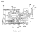
- an electrical connector 1 has a female part 2 with a plurality of female contact pins T 1 mounted inside a female housing, and a male part 10 with male contact pins T 2 , to which the female contact pins T 1 are electrically coupled, mounted inside a male housing 11; and the female part 2 is so structured that a sensing member (Connector Position Assurance; "CPA" below) 7 that senses the mated state with the male part 10 is mounted on the outer wall surface of the female housing.
- CPA Connector Position Assurance
- the female part 2 has two female contact pins T 1 , T 1 , a female housing in which the female contact pins T 1 , T 1 are housed, and a tubular seal member 8 and contact latching member ("TPA" below) 9 that are installed inside the female housing's insertion opening 3 A .
- the female housing has: at the front, an insertion opening 3 A into which the housing of the male part 10 is inserted; at the rear, a tubular outer housing 3 with an opening 3 B (see Fig. 5) into which an inner housing 4 is inserted; and in the interior, receiving holes 41 and 42 that receive the two female contact pins T 1 , T 1 ; and is so configured that the inner housing 4 is tubular, is inserted into the outer housing 3's opening 3 B , and fits over the male housing 11 of the male part 10 (see Fig. 5).
- the outer housing 3's insertion opening 3 A takes a rectangular shape with mutually opposed short edges and long edges, while its outer periphery is covered by mutually opposed left and right sidewalls 33 and 34, and top and bottom walls 31 and 32. Also, the outer housing 3 has a cavity 30 (see Figs. 4 and 5) formed in its interior, the whole being formed as an insulating plastic molding in a flattened tubular shape. Flat-bottomed slots 33a and 34a are formed in a roughly central position along the outer periphery of the outer housing 3 in the longitudinal direction, or more specifically, on the respective outer faces of the left and right sidewalls 33, 34.
- the width and depth of the flat-bottomed slots 33a, 34a are sufficiently large to receive the wire-like body of the clip member 6 to be described later. Roughly in the center of the flat-bottomed slots 33a, 34a there are formed through-holes 33a' and 34a' that penetrate through the sidewalls (see Fig. 5). The latching protrusions 62 A and 66 A of the clip member 6 are projected through these through-holes 33a', 34a'.
- two arm pieces 31a and 31b possessing resilience are extended from the outer face of the top wall 31, and at the end of each arm piece 31a, 31b there are formed upward-protruding hook-like latching claws 31a' and 31b' (see Fig. 3).
- the resilience of the arm pieces 31a, 31b stems from the material of the outer housing 3, the thickness of the top wall 31, and a narrow slot 31 0 set in the top wall 31 in the longitudinal direction.
- a guiding tab 31c for guiding the sliding motion of the CPA 7 is formed at the rear of the outer housing 3.
- a step portion 32 0 into which the bottom portion 60B of the clip member 6 latches (see Fig. 11B).
- the inner housing 4 is constituted of a rectangular tubular body and is formed as an insulating plastic molding, as shown in Figs. 1 and 4 to 6.
- Latch portions 41a and 41b for latching the contact pins T 1 , T 1 are formed in the receiving holes 41 and 42 respectively.
- One of the latch portions, 41a which is formed inside receiving hole 41, is not shown in the drawings. Movement of the latch portions 41a, 41b is restricted by the TPA 9.
- a tubular seal member 8 and the TPA 9 are fitted onto the outer periphery of the inner housing 4.
- Fig. 7 illustrates the clip member in Fig. 1, Fig. 7A being an enlarged perspective view of the clip member in Fig. 2 and Fig. 7B being a perspective view from direction VIIB in Fig. 7A.
- the clip member 6 is wound, in a state in which resilience is imparted thereto, onto the outer periphery of the outer housing 3 of the female part 2.
- the clip member 6 is bent in a plurality of bend portions 6 A to 6 H , which are joined by coupling portions 60 to 68.
- the member is formed as a body resembling a single spring wire of a particular thickness.
- the bottom portion 60B of the clip member 6 is composed of coupling portions 63 to 65 linking the bend portions 6c to 6 F , and is formed to be curved in such a manner as to latch into the step portion 32 0 of the bottom 32 of the housing 3.
- the two end portions 60 and 68 of the clip member 6 are the pressing portions. Also, in the coupling portions 62 and 66, which are proximate to and face the end portions 60 and 68 respectively, there are formed latching protrusions 62 A and 66 A that point inward at each other. These latching protrusions 62 A , 66 A are projected through the through-holes 33a', 33b' in the outer housing 3 into the cavity 30 in the outer housing 3. Further, in the coupling portion 67, which constitutes the upper edge, there is formed an upward-projecting latching protrusion 67 A , which engages with the CPA 7.
- the latching protrusion 67 A is located on a vertical virtual line that crosses at right angles, roughly near the center, a virtual line joining the latching protrusions 62 A and 66 A , and is formed so as to project outward from the coupling portion 67.
- the latching protrusions 62 A , 66 A will move in the directions of arrows Y A and Y B because of being pushed by the saliencies 11 0 , 11 0 of the male housing 11, and simultaneously with such motion, the latching protrusion 67 A will be slid in direction Y 3 .
- Such motion of the latching protrusion 67A removes the restriction on movement of the CPA 7's latching bar 73a', to be described later, so that the CPA 7 can be slid in the mating direction. Since the clip member 6 can be formed by bend-processing of a single spring wire, it can be fabricated simply, and moreover at low cost, to match the shape of the outer housing 3.
- the shape of the female part 2's section orthogonal to the longitudinal direction is rectangular, it is not limited to this shape and could equally well be another shape such as oval or circular. Further, the shape of the clip member 6 will be altered to match such shape variation.
- the CPA 7 has: an upper plate portion 73 sufficiently large to cover the top wall 31 of the outer housing 3; side plate portions 71 and 72 sufficiently large to cover partially the two sidewalls 33, 34 of the outer housing 3; and a bottom portion 75 in which are formed guide slots 75a and 75b that engage with the guiding tab 31c.
- the front is left open as open portion 7 A , and the rear is closed over by a rear wall 74.
- the CPA is formed as an insulating plastic molding and, viewed directly from the front, is composed of members arranged more or less in a broad, inverted U-shape.
- a sensing arm 73a which possesses resilience.
- a latching bar 73a' that latches into the latching protrusion 67 A of the clip member 6.
- the sensing arm 73a performs the function of sensing whether or not mating with the male part 10 has been effected in the regular position.
- Resilience is imparted to the sensing arm 73a by the thickness of the upper plate portion 73 and by the provision of a pair of slits 73 1 and 73 2 in the longitudinal direction of the upper plate portion.
- the bottom portion 75 there are formed guide slots 75a and 75b.
- engaging holes 74 1 and 74 2 into which the latching bars 31a', 31b' of the outer housing 3 engage are formed in the rear wall 74 (see Fig. 3A).
- the CPA 7 is installed so as to be slidable in the back-forward direction of the outer housing 3, that is, in the direction of mating with the male part 10.
- narrow slots 72 A , 72 A see Fig. 9) into which the spring wire-like body of the clip member 6 penetrates.
- the tubular seal member 8 has, in its interior, a through-hole 8 0 sufficiently large to fit over the outer periphery of the inner housing 4, and, formed on its outer wall, a plurality of concavo-convexities 8a, as shown in Figs. 2 and 3.
- the tubular seal member 8 is formed from a tubular resilient member of rubber or the like having a particular thickness.
- the TPA 9 formed as an insulating plastic molding, has a tubular portion 9a with a through-hole 9 0 in the interior thereof that is sufficiently large to fit over the outer periphery of the inner housing 4, and a pair of arm pieces 9 1 and 9 2 that extend outward from the tubular portion 9a to a certain distance.
- the arm pieces 9 1 and 9 2 perform the function of securing the contact pins T 1 , T 2 , by pushing down the latch portions 41a and 42a that are formed in the receiving holes 41, 42 inside the inner housing 4.
- the female part 2 with the structure described above is assembled via the following procedure.
- a seal member W 0 is inserted through the rear end of the inner housing 4 and seals the spaces around the wires W. Thanks to this, any water droplets or the like that travel along the wires will not enter into the female housing interior.
- the inner housing 4 thus assembled is inserted through the opening 3 B in the rear of the outer housing 3 and secured in place. Such securing is effected via mating into the tubular portion 35 in which the opening 3 B of the housing 3 is formed.
- the clip member 6 is installed to the outer housing 3 either before or after the inner housing 4 is installed. Such installation is effected by stretching out the clip member 6 and fitting it over the outer periphery of the outer housing 3 in such a manner that its latching protrusions 62 A , 66 A project into the interior of the outer housing 3 through the through-holes 33a', 34a'. Through such installation, the single spring wire-like body that constitutes the clip member 6 becomes wound onto the outer wall surface of the outer housing 3. After that, the CPA 7 is installed to the outer housing 3.
- Such installation is carried out by bringing the two sidewalls 71, 72 of the CPA 7 into contact with the two sidewalls 33, 34 of the housing 3, and furthermore passing the pair of arm pieces 31a, 31b of the top plate portion 73 through the engaging holes 74 1 , 74 2 and causing the latching bars 31a', 31b' to latch into the latching step portions 74 0 inside the engaging holes 74 1 , 74 2 (see Fig. 6).
- the latching of the latching bar 31b' into the latching step portion 74 0 is omitted in Fig. 6.
- the guide protrusion 31c of the outer housing 3 is inserted into the guide slots 75a, 75b of the CPA 7.
- the CPA 7 is installed so as to-be readily slidable in the front-back direction of the outer housing 3, that is, the direction of mating with the male part 10, and, thanks to the engaging of the latching bars 31a', 31b' with the latching step portions 74 0 , 74 0 , is retained in place.
- the CPA 7 is slidable between a standby position and a regular mating position.
- the male part 10 has a male housing 11, with a cavity 12, that is sufficiently large to mate into the insertion opening 3 A of the female part 2, and two male contact pins T 2 , T 2 that are mounted inside the male housing 11, as shown in Figs. 1 and 5.
- engaging slots 11 A and 11 B into which the latching protrusions 62 A , 66 A of the clip member 6 engage.
- saliency 11 0 that slopes downward in the direction of mating with the female part 2.
- the latching protrusions 62 A , 66 A of the clip member 6 project into the cavity 30 via the through-holes 33a', 33b' in the outer housing 3, as shown in Fig. 5.
- the latching bar 73a' of the CPA 7 contacts the latching protrusion 67A of the clip member 6, so that forward motion of the CPA 7, that is, in the direction of mating with the male part 10, is inhibited and thus the sliding motion thereof is restricted.
- the housing 11 of the male part 10 is inserted into the insertion opening 3 A of the female part 2, whereupon, as shown in Fig. 8, the saliencies 11 0 , 11 0 of the male housing 11 contact against the latching protrusions 62 A , 66 A of the clip member 6. Then, as the male part 10 is pushed in further, the latching protrusions 62 A , 66 A are pushed along the sloping surfaces of the saliencies 11 0 , 11 0 and move through the through-holes 33a', 34b' , subsequently being pushed out into the cavity 30.
- the latching protrusions 62 A , 66 A of the clip member 6 are pushed out through the cavity 30, and simultaneously the latching protrusion 67 A is slid in the direction indicated by Y 3 in Fig. 7.
- the latching protrusion 67 A moves laterally in this way, the position of contact between the latching protrusion 67 A and the CPA 7's latching bar 73a' shifts, so that the CPA 7 can be slid in the direction of the male part 10.
- the CPA 7 is then slid in such mating direction, following which the latching protrusions 62 A , 66 A of the clip member 6 enter into the narrow slots 11A, 11B, and simultaneously the latching protrusion 67 A returns to its original position.
- the latching protrusion 67 A engages with the inner face of the latching bar 73a' and is restricted from moving rearward (see Fig. 9).
- the CPA 7 is able to ensure that the female part 2 and male part 10 are fully coupled in the regular position.
- the two parts 2, 10 can be reliably coupled, with semi-mated coupling prevented. More precisely, the fact that the operations of the clip member and sliding sensing member are linked means that the two connector parts 2, 10 are mated and locked reliably. Moreover, mounting of the clip member onto the female housing is effected by clipping the member onto the outer wall surface of the female housing. Therefore such mounting does not require a specially complex shape to be used for the female housing. This means that the female housing is simple to mold, and both connector parts 2, 10 can be made compact. What is more, such mounting is simple.
- decoupling of the male part 12 and female part 2 is carried out by forcibly retracting the CPA 7 toward the rear of the female part 2.
- Such forcible retraction is effected by utilizing the resilience of the sensing arm 73 of the CPA 7 to cause the latching bar 73a' to move past the latching protrusion 67 A of the clip member 6, and so to retract.
Landscapes
- Engineering & Computer Science (AREA)
- Computer Security & Cryptography (AREA)
- Details Of Connecting Devices For Male And Female Coupling (AREA)
Applications Claiming Priority (1)
| Application Number | Priority Date | Filing Date | Title |
|---|---|---|---|
| SG200606189-9A SG141248A1 (en) | 2006-09-08 | 2006-09-08 | Electrical connector |
Publications (2)
| Publication Number | Publication Date |
|---|---|
| EP1898498A2 true EP1898498A2 (fr) | 2008-03-12 |
| EP1898498A3 EP1898498A3 (fr) | 2008-06-04 |
Family
ID=38805578
Family Applications (1)
| Application Number | Title | Priority Date | Filing Date |
|---|---|---|---|
| EP07253562A Withdrawn EP1898498A3 (fr) | 2006-09-08 | 2007-09-07 | Connecteur électrique |
Country Status (6)
| Country | Link |
|---|---|
| US (1) | US7479025B2 (fr) |
| EP (1) | EP1898498A3 (fr) |
| JP (1) | JP2008066290A (fr) |
| KR (1) | KR20080023184A (fr) |
| CN (1) | CN101141034A (fr) |
| SG (1) | SG141248A1 (fr) |
Cited By (8)
| Publication number | Priority date | Publication date | Assignee | Title |
|---|---|---|---|---|
| WO2015007268A1 (fr) * | 2013-07-18 | 2015-01-22 | HARTING Electronics GmbH | Dispositif de verrouillage de connecteurs enfichables |
| WO2015036611A1 (fr) * | 2013-09-16 | 2015-03-19 | Tyco Electronics France Sas | Connecteur électrique pour un système de retenue de sécurité |
| WO2015036609A1 (fr) * | 2013-09-16 | 2015-03-19 | Tyco Electronics France Sas | Connecteur à ressort de verrouillage |
| FR3010841A1 (fr) * | 2013-09-16 | 2015-03-20 | Tyco Electronics France Sas | Connecteur a verrouillage a ressort |
| EP2876745A1 (fr) * | 2013-11-25 | 2015-05-27 | Tyco Electronics France SAS | Connecteur électrique pour système de retenue de sécurité |
| FR3013912A1 (fr) * | 2013-11-25 | 2015-05-29 | Tyco Electronics France Sas | Connecteur electrique pour systeme de retenue de securite |
| EP2996205A1 (fr) * | 2014-09-09 | 2016-03-16 | Carrier Kheops Bac | Verrou de retenue, corps pour boîtier de prise et similaire |
| DE112007002161B4 (de) | 2006-09-15 | 2021-08-05 | J.S.T. Mfg. Co., Ltd. | Steckverbindung |
Families Citing this family (36)
| Publication number | Priority date | Publication date | Assignee | Title |
|---|---|---|---|---|
| JP4716123B2 (ja) * | 2006-06-16 | 2011-07-06 | 住友電装株式会社 | コネクタ用キャップの保持構造 |
| JP4567645B2 (ja) | 2006-09-15 | 2010-10-20 | 日本圧着端子製造株式会社 | コネクタ |
| EP2053702B1 (fr) * | 2007-10-24 | 2012-06-20 | Sumitomo Wiring Systems, Ltd. | Dispositif de connecteur et structure de verrouillage |
| JP4959505B2 (ja) * | 2007-10-24 | 2012-06-27 | 日本圧着端子製造株式会社 | 掛け止め金具付きコネクタハウジング、掛け止め金具付きコネクタ及び電気コネクタ装置 |
| JP5005498B2 (ja) * | 2007-10-24 | 2012-08-22 | 日本圧着端子製造株式会社 | 掛け止め金具、掛け止め金具付きコネクタハウジング及び掛け止め金具付きコネクタ |
| JP4515516B2 (ja) * | 2008-09-09 | 2010-08-04 | 株式会社アイペックス | コネクタ装置 |
| JP5342198B2 (ja) * | 2008-09-16 | 2013-11-13 | 矢崎総業株式会社 | コネクタ |
| JP5314535B2 (ja) * | 2009-08-25 | 2013-10-16 | 矢崎総業株式会社 | コネクタ |
| US8062049B2 (en) * | 2010-01-15 | 2011-11-22 | Tyco Electronics Corporation | Latch assembly for a connector assembly |
| JP5524728B2 (ja) * | 2010-06-10 | 2014-06-18 | 日本圧着端子製造株式会社 | 結合検知手段を有するコネクタ |
| DE202010009597U1 (de) * | 2010-06-28 | 2010-09-09 | Rosenberger Hochfrequenztechnik Gmbh & Co. Kg | Steckverbinder mit einer radial wirkenden Rasteinrichtung |
| JP2014082044A (ja) * | 2012-10-15 | 2014-05-08 | Sumitomo Wiring Syst Ltd | スプリングロック式コネクタ |
| JP5854281B2 (ja) * | 2012-10-15 | 2016-02-09 | 住友電装株式会社 | スプリングロック式コネクタ |
| JP6279846B2 (ja) * | 2013-07-01 | 2018-02-14 | 日本圧着端子製造株式会社 | 電気コネクタ、およびスクイブの接続装置 |
| US9614323B2 (en) * | 2013-07-31 | 2017-04-04 | J.S.T. Corporation | Electrical connector |
| CN105531886B (zh) * | 2013-09-16 | 2018-07-03 | 泰科电子法国公司 | 一种用于安全约束系统的电连接器 |
| US9318836B2 (en) * | 2014-02-06 | 2016-04-19 | Dai-Ichi Seiko Co., Ltd. | Electric connector |
| JP6263064B2 (ja) * | 2014-03-26 | 2018-01-17 | 矢崎総業株式会社 | コネクタ |
| JP6245526B2 (ja) * | 2014-10-17 | 2017-12-13 | 株式会社オートネットワーク技術研究所 | コネクタ |
| JP6375246B2 (ja) * | 2015-02-25 | 2018-08-15 | 矢崎総業株式会社 | コネクタの嵌合構造 |
| CN107431300A (zh) * | 2015-03-12 | 2017-12-01 | 心脏起搏器股份公司 | 电连接器及制造电连接器的方法 |
| EP3335282B1 (fr) | 2015-08-12 | 2021-04-21 | Commscope Technologies LLC | Connecteur électrique enfichable |
| WO2017038850A1 (fr) * | 2015-08-31 | 2017-03-09 | 矢崎総業株式会社 | Structure imperméable pour connecteur |
| DE102015120025A1 (de) | 2015-11-19 | 2017-05-24 | HARTING Electronics GmbH | Steckverbinder mit Sicherungselement |
| JP6243897B2 (ja) * | 2015-12-15 | 2017-12-06 | 矢崎総業株式会社 | コネクタ |
| EP3413406B1 (fr) * | 2016-02-18 | 2021-04-07 | Shenzhen Linko Electric Co., Ltd. | Connecteur industriel et structure de connexion |
| JP6404277B2 (ja) * | 2016-07-12 | 2018-10-10 | 矢崎総業株式会社 | コネクタ |
| JP6417370B2 (ja) * | 2016-07-29 | 2018-11-07 | 矢崎総業株式会社 | コネクタ |
| CN106486836B (zh) * | 2016-11-18 | 2018-10-30 | 安徽江淮汽车集团股份有限公司 | 一种公端子护套与母端子护套配合结构 |
| JP6580548B2 (ja) * | 2016-12-22 | 2019-09-25 | 矢崎総業株式会社 | コネクタ |
| US9935389B1 (en) * | 2017-02-23 | 2018-04-03 | Sumitomo Wiring Systems, Ltd. | Inline connector housing assemblies with removable TPA |
| IT201700057099A1 (it) | 2017-05-25 | 2018-11-25 | Tyco Electronics Amp Italia Srl | Dispositivo di connettore elettrico |
| CN107565269A (zh) * | 2017-07-18 | 2018-01-09 | 安顺云首创科技开发有限公司 | 一种防错插电连接器 |
| JP2019050169A (ja) * | 2017-09-12 | 2019-03-28 | 住友電装株式会社 | コネクタ |
| CN110611221B (zh) * | 2018-06-14 | 2021-02-26 | 鸿富锦精密电子(天津)有限公司 | 锁固结构及采用该锁固结构的线缆接头组件 |
| US11251560B2 (en) * | 2019-03-11 | 2022-02-15 | TE Connectivity Services Gmbh | Terminal position assurance member with multiple latches |
Citations (1)
| Publication number | Priority date | Publication date | Assignee | Title |
|---|---|---|---|---|
| US5823813A (en) | 1997-01-21 | 1998-10-20 | Itt Manufacturing Enterprises, Inc. | Connector position assurance device |
Family Cites Families (6)
| Publication number | Priority date | Publication date | Assignee | Title |
|---|---|---|---|---|
| DE19850521C1 (de) * | 1998-11-03 | 2001-05-17 | Hirschmann Richard Gmbh | Elektrische Steckverbindung |
| JP3997858B2 (ja) | 2002-07-24 | 2007-10-24 | 住友電装株式会社 | 嵌合検知コネクタ |
| US6811424B2 (en) | 2003-03-26 | 2004-11-02 | Fci Americas Technology, Inc. | Electrical connector having connector position assurance member |
| US6857892B2 (en) | 2003-06-05 | 2005-02-22 | Fci Americas Technology, Inc. | Electrical connector with connector position assurance member |
| US7153172B2 (en) * | 2005-05-19 | 2006-12-26 | Deutsch Engineered Connecting Devices, Inc. | Fuel injector connector |
| DE102005060657A1 (de) * | 2005-12-19 | 2007-06-28 | Robert Bosch Gmbh | Elektrische Steckverbindung |
-
2006
- 2006-09-08 SG SG200606189-9A patent/SG141248A1/en unknown
-
2007
- 2007-07-18 JP JP2007187044A patent/JP2008066290A/ja active Pending
- 2007-09-05 CN CNA200710149166XA patent/CN101141034A/zh active Pending
- 2007-09-07 US US11/899,665 patent/US7479025B2/en not_active Expired - Fee Related
- 2007-09-07 KR KR1020070090915A patent/KR20080023184A/ko not_active Abandoned
- 2007-09-07 EP EP07253562A patent/EP1898498A3/fr not_active Withdrawn
Patent Citations (1)
| Publication number | Priority date | Publication date | Assignee | Title |
|---|---|---|---|---|
| US5823813A (en) | 1997-01-21 | 1998-10-20 | Itt Manufacturing Enterprises, Inc. | Connector position assurance device |
Cited By (10)
| Publication number | Priority date | Publication date | Assignee | Title |
|---|---|---|---|---|
| DE112007002161B4 (de) | 2006-09-15 | 2021-08-05 | J.S.T. Mfg. Co., Ltd. | Steckverbindung |
| WO2015007268A1 (fr) * | 2013-07-18 | 2015-01-22 | HARTING Electronics GmbH | Dispositif de verrouillage de connecteurs enfichables |
| US9425552B2 (en) | 2013-07-18 | 2016-08-23 | HARTING Electronics GmbH | Locking apparatus for plug connectors |
| WO2015036611A1 (fr) * | 2013-09-16 | 2015-03-19 | Tyco Electronics France Sas | Connecteur électrique pour un système de retenue de sécurité |
| WO2015036609A1 (fr) * | 2013-09-16 | 2015-03-19 | Tyco Electronics France Sas | Connecteur à ressort de verrouillage |
| FR3010841A1 (fr) * | 2013-09-16 | 2015-03-20 | Tyco Electronics France Sas | Connecteur a verrouillage a ressort |
| EP2876745A1 (fr) * | 2013-11-25 | 2015-05-27 | Tyco Electronics France SAS | Connecteur électrique pour système de retenue de sécurité |
| FR3013912A1 (fr) * | 2013-11-25 | 2015-05-29 | Tyco Electronics France Sas | Connecteur electrique pour systeme de retenue de securite |
| EP2996205A1 (fr) * | 2014-09-09 | 2016-03-16 | Carrier Kheops Bac | Verrou de retenue, corps pour boîtier de prise et similaire |
| WO2016037755A1 (fr) * | 2014-09-09 | 2016-03-17 | Carrier Kheops Bac | Loquet de retenue, corps pour boîtier de réceptacle et similaires |
Also Published As
| Publication number | Publication date |
|---|---|
| EP1898498A3 (fr) | 2008-06-04 |
| JP2008066290A (ja) | 2008-03-21 |
| US7479025B2 (en) | 2009-01-20 |
| KR20080023184A (ko) | 2008-03-12 |
| CN101141034A (zh) | 2008-03-12 |
| US20080064250A1 (en) | 2008-03-13 |
| SG141248A1 (en) | 2008-04-28 |
Similar Documents
| Publication | Publication Date | Title |
|---|---|---|
| US7479025B2 (en) | Electrical connector | |
| US7404731B2 (en) | Electrical connector | |
| CN111326915B (zh) | 包括成型闩锁的插头连接器 | |
| US6241542B1 (en) | Connector with shorting terminal | |
| US7134901B2 (en) | Connector with a moving plate | |
| CN113285305A (zh) | 拉带连接器及其组件 | |
| CN101218714B (zh) | 带有接线端位置保证装置的连接器组件 | |
| JP3317390B2 (ja) | コネクタ | |
| EP1085617B1 (fr) | Connecteur | |
| JPH09245869A (ja) | 端子係止具付きコネクタ | |
| US7568923B2 (en) | Connector and connector assembly | |
| JP2005183297A (ja) | コネクタ | |
| CN101017941B (zh) | 连接器和连接器组件 | |
| CN215184820U (zh) | 拉带连接器及其组件 | |
| CN1645677B (zh) | 连接器 | |
| JP3687537B2 (ja) | 分割コネクタ | |
| JP4434147B2 (ja) | コネクタ | |
| EP1801926B1 (fr) | Connecteur et ensemble de connecteurs | |
| CN214379112U (zh) | 连接器 | |
| US20050142923A1 (en) | Connector | |
| CN210016048U (zh) | 电连接器 | |
| JP3988424B2 (ja) | コネクタ | |
| JP5565184B2 (ja) | コネクタ | |
| JP4577201B2 (ja) | コネクタ | |
| JP2000306632A (ja) | コネクタ |
Legal Events
| Date | Code | Title | Description |
|---|---|---|---|
| PUAI | Public reference made under article 153(3) epc to a published international application that has entered the european phase |
Free format text: ORIGINAL CODE: 0009012 |
|
| AK | Designated contracting states |
Kind code of ref document: A2 Designated state(s): AT BE BG CH CY CZ DE DK EE ES FI FR GB GR HU IE IS IT LI LT LU LV MC MT NL PL PT RO SE SI SK TR |
|
| AX | Request for extension of the european patent |
Extension state: AL BA HR MK YU |
|
| PUAL | Search report despatched |
Free format text: ORIGINAL CODE: 0009013 |
|
| AK | Designated contracting states |
Kind code of ref document: A3 Designated state(s): AT BE BG CH CY CZ DE DK EE ES FI FR GB GR HU IE IS IT LI LT LU LV MC MT NL PL PT RO SE SI SK TR |
|
| AX | Request for extension of the european patent |
Extension state: AL BA HR MK RS |
|
| RIC1 | Information provided on ipc code assigned before grant |
Ipc: H01R 13/641 20060101ALN20080429BHEP Ipc: H01R 13/639 20060101ALI20080429BHEP Ipc: H01R 13/627 20060101AFI20071220BHEP |
|
| 17P | Request for examination filed |
Effective date: 20080704 |
|
| 17Q | First examination report despatched |
Effective date: 20080804 |
|
| AKX | Designation fees paid |
Designated state(s): CZ DE FR IT PL |
|
| STAA | Information on the status of an ep patent application or granted ep patent |
Free format text: STATUS: THE APPLICATION IS DEEMED TO BE WITHDRAWN |
|
| 18D | Application deemed to be withdrawn |
Effective date: 20120403 |