EP1900883A2 - Odour seal for an urinal - Google Patents
Odour seal for an urinal Download PDFInfo
- Publication number
- EP1900883A2 EP1900883A2 EP07450140A EP07450140A EP1900883A2 EP 1900883 A2 EP1900883 A2 EP 1900883A2 EP 07450140 A EP07450140 A EP 07450140A EP 07450140 A EP07450140 A EP 07450140A EP 1900883 A2 EP1900883 A2 EP 1900883A2
- Authority
- EP
- European Patent Office
- Prior art keywords
- control valve
- odor
- odor control
- trap according
- odor trap
- Prior art date
- Legal status (The legal status is an assumption and is not a legal conclusion. Google has not performed a legal analysis and makes no representation as to the accuracy of the status listed.)
- Withdrawn
Links
Images

Classifications
-
- E—FIXED CONSTRUCTIONS
- E03—WATER SUPPLY; SEWERAGE
- E03C—DOMESTIC PLUMBING INSTALLATIONS FOR FRESH WATER OR WASTE WATER; SINKS
- E03C1/00—Domestic plumbing installations for fresh water or waste water; Sinks
- E03C1/12—Plumbing installations for waste water; Basins or fountains connected thereto; Sinks
- E03C1/28—Odour seals
- E03C1/298—Odour seals consisting only of non-return valve
-
- E—FIXED CONSTRUCTIONS
- E03—WATER SUPPLY; SEWERAGE
- E03D—WATER-CLOSETS OR URINALS WITH FLUSHING DEVICES; FLUSHING VALVES THEREFOR
- E03D11/00—Other component parts of water-closets, e.g. noise-reducing means in the flushing system, flushing pipes mounted in the bowl, seals for the bowl outlet, devices preventing overflow of the bowl contents; devices forming a water seal in the bowl after flushing, devices eliminating obstructions in the bowl outlet or preventing backflow of water and excrements from the waterpipe
- E03D11/18—Siphons
-
- E—FIXED CONSTRUCTIONS
- E03—WATER SUPPLY; SEWERAGE
- E03D—WATER-CLOSETS OR URINALS WITH FLUSHING DEVICES; FLUSHING VALVES THEREFOR
- E03D13/00—Urinals ; Means for connecting the urinal to the flushing pipe and the wastepipe; Splashing shields for urinals
Definitions
- the present invention relates to an odor trap for draining a urinal with intermittent surge.
- Urinals are basically differentiated between water-flushed and waterless urinals. Water-flushed urinals ensure a high degree of hygiene, as a complete flushing is carried out after each use.
- a Rohrknie- or a Spiralsiphon preferably a so-called Absaugsiphon, which is a siphon, which has a substantially uniform or slightly narrowing flow cross-section with a corresponding suction, so that no deposits can accumulate in dead zones.
- the surge siphon is always rinsed with fresh water after each use and filled so that an odor trap can be achieved with almost unlimited service life.
- odor control valves in waterless urinals provide a sufficient odor trap
- all known designs have only a very limited life, since they are operated directly with urine. After a short time, proteins that precipitate from the urine thicken into a gelatinous mass that blocks the odor control valve and makes it unusable.
- the odor control valves have to be exchanged after about 7,000 to 14,000 uses, which can already be achieved in high-frequency situations after 1 to 2 weeks. This not only represents a considerable material cost factor, but is also a specialized specialist work with corresponding personnel expenses.
- the aim of the invention is to combine the advantages of conventional water-flushed urinals, such as high hygiene, low odor and long service life, with those of waterless urinals, such as high water savings with sufficient odor reduction, without the above-mentioned disadvantages of the various systems to take.
- odor trap of the invention is therefore hygienic, water-saving, maintenance-free and self-cleaning and also meets all the standards of a conventional sewer gas closure.
- a preferred embodiment of the odor trap of the invention is further characterized by a shunt which at least partially bridges the odor control valve during the surge flushing process.
- the shunt connection is formed by a large-diameter flow channel which branches off laterally above the odor control valve, contains a siphon and discharges into the suction siphon.
- a surge flushing which exceeds the capacity of the odor control valve, the excess thus flows automatically through the shunt connection.
- the siphon in the shunt connection ensures the odor trap against the Absaugsiphon, which is operated between the Schwall Erasmusvor réellen with urine.
- a production engineering particularly simple construction of this shunt connection is characterized in that the odor control valve is at a distance below the drain to form the branch of the flow channel.
- the shunt connection is formed by lifting the odor control valve from its seat by means of a lifting device.
- the lifting device is an electromagnet arranged at the outlet, which cooperates with a magnet armature arranged on the odor control valve, which allows an encapsulated arrangement.
- odor control valve one of the aforementioned valves known per se, u.zw. prefers membrane, float or barrier fluid valves. This allows - in conjunction with a standard siphoning siphon - a structure of the odor trap according to the invention of largely standardized parts.
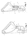
- a urinal 1 with an inlet 2 and a drain 3 is shown.
- a conventional flushing device for the intermittent surge flushing of the urinal 1, for example for the time-controlled periodic surge flushing, e.g. hourly or daily, or for use-dependent controlled surge flushing, e.g. after 100 or 1,000 uses.
- the odor trap 5 comprises in succession an odor control valve 6 of a known type and a Absaugsiphon-7 per se known type.
- the odor control valve 6 is connected directly to the outlet 3 of the urinal or directly inserted into this, i. without any attachment grid (sieve), as it is otherwise installed to protect odor control valves from coarse contaminants.
- the structure of the odor control valve 6 will be explained in more detail with reference to FIGS. 2 to 5.
- the Absaugsiphon 7 is in the example shown a so-called Spiralsiphon, i. a siphon having a helically curved flow channel which has a substantially constant or only slightly narrowing cross-section in order to achieve the suction effect known in the art, wherein each turn of the spiral forms a pipe elbow.
- Spiralsiphon i. a siphon having a helically curved flow channel which has a substantially constant or only slightly narrowing cross-section in order to achieve the suction effect known in the art, wherein each turn of the spiral forms a pipe elbow.
- the axis of the spiral is parallel and horizontal to the plane of the drawing.
- the siphoning siphon 7 is also of a standardized type, ie a standard siphon, which fulfills all regulatory requirements with regard to sewer gas closure, pressure fluctuations, flow cross-section and coking capacity for coarse contaminants. Regardless of the operating position of the odor control valve 6 thus all regulatory requirements for a proper Sewer gas seal already met by Absaugsiphon 7 alone.
- FIG. 2 shows a variant 5 'of the odor trap of FIG. 1.
- the odor trap 5' has a shunt connection 8 parallel to the odor control valve 6.
- the shunt connection 8 is capable of at least partially bridging the odor control valve 6 during the surge flushing operation, i. to establish a direct connection from drain 3 to suction siphon 7.
- the odor control valve 6 and shunt 8 assembly is shown in more detail in FIG.
- the odor control valve 6 is in this embodiment, a diaphragm valve with a tubular membrane 9 from a piece of flat tube which is forced through the top by entering liquid and these pass, but after the passage of the liquid closes again due to its elasticity to a repelling odor gases to prevent.
- the shunt 8 is a Moneloger flow channel which branches off laterally above the odor control valve 6, a small siphon 10 in the form of a chicane and at 11 - together with the output of the odor control valve 6 - to the Absaugsiphon 7 out.
- the diversion of the shunt connection 8 above the odor control valve 6 is achieved in the example shown in that the odor control valve 6 is located at a distance 12 below the outlet 3 of the urinal 1. Together with the fact that the flow resistance of the odor control valve 6 is greater than that of the shunt connection 8, this causes each rinsing process that the rinse water not only through the odor control valve 6, but also on this over the shunt connection 8 to Absaugsiphon 7 abrinnt. After Schwall Erasmusvorgang remains fresh water in the siphon 10 and thus closes the shunt connection 8 to smell from the Absaugsiphon 7, which is operated between the Schwall Anlagenvor réellen with urine.
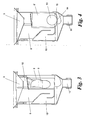
- Fig. 4 shows an alternative embodiment with an odor control valve 6 '.
- the odor control valve 6 ' includes a float 13, which closes the drain opening 14 of a funnel 15 in the idle state.
- the float 13 Upon entry of liquid, the float 13 is first raised and thus releases the drain opening 14 to Absaugsiphon 7 back.
- Absaugsiphon 7 In a surge flushing in which a large amount of water impinges on the float 13 and this lapped around all sides, causes the pressure difference due to the lack of buoyancy at the location of the drain opening 14 that the buoyant body 13 is pressed down and the drain opening 14 closes; In this case, the entire rinse water is forwarded via the shunt connection 8 to Absaugsiphon 7.
- FIG. 5 shows a further variant 5 "of the odor trap with an odor control valve 6" which, as in FIG. 3, is designed as a diaphragm valve with a tubular membrane 9 and sits directly in a conical seat 16 of the outlet 3.
- the odor control valve 6 " With the aid of a lifting device 17, the odor control valve 6 "is lifted out of its seat 16 during the flushing operation, whereby the gap formed between the odor control valve 6" and the seat 16 forms the shunt connection 8. The majority of the rinse water flows through the shunt connection 8 directly to Absaugsiphon 7, while a part also flows through the odor control valve 6 ".
- an electromagnet 18 is arranged around the odor control valve 6 "which cooperates with a corresponding armature 19 arranged on the odor control valve 6".
Landscapes
- Engineering & Computer Science (AREA)
- Health & Medical Sciences (AREA)
- Life Sciences & Earth Sciences (AREA)
- Hydrology & Water Resources (AREA)
- Public Health (AREA)
- Water Supply & Treatment (AREA)
- Environmental & Geological Engineering (AREA)
- Sanitary Device For Flush Toilet (AREA)
Abstract
Description
Die vorliegende Erfindung betrifft einen Geruchsverschluß für den Ablauf eines Urinals mit intermittierender Schwallspülung.The present invention relates to an odor trap for draining a urinal with intermittent surge.
Bei Urinalen wird grundsätzlich zwischen wassergespülten und wasserlosen Urinalen unterschieden. Wassergespülte Urinale gewährleisten einen hohen Hygienegrad, da nach jeder Benutzung eine vollständige Schwallspülung durchgeführt wird. Als Geruchsverschluß gegenüber dem Abwasserkanal dient ein Rohrknie- oder ein Spiralsiphon, bevorzugt ein sogenannter Absaugsiphon, das ist ein Siphon, welcher einen weitgehend gleichförmigen oder sich geringfügig verengenden Strömungsquerschnitt mit entsprechender Saugwirkung besitzt, so daß sich keine Ablagerungen in Totzonen ansammeln können. Durch die Schwallspülung wird der Absaugsiphon nach jeder Benutzung stets mit Frischwasser gespült und gefüllt, so daß ein Geruchsverschluß mit nahezu unbegrenzter Standzeit erreicht werden kann.Urinals are basically differentiated between water-flushed and waterless urinals. Water-flushed urinals ensure a high degree of hygiene, as a complete flushing is carried out after each use. As an odor trap against the sewer a Rohrknie- or a Spiralsiphon, preferably a so-called Absaugsiphon, which is a siphon, which has a substantially uniform or slightly narrowing flow cross-section with a corresponding suction, so that no deposits can accumulate in dead zones. The surge siphon is always rinsed with fresh water after each use and filled so that an odor trap can be achieved with almost unlimited service life.
Der Nachteil von wassergespülten Urinalen ist ihr hoher Wasserverbrauch von ca. 4-6 1 pro Spülung. In Hochfrequenzlagen wie Flughäfen, Stadien, öffentlichen Raststätten usw., wo mit hunderten bis tausenden Benützungen pro Tag zu rechnen ist, wird daher die Anzahl der Schwallspülvorgänge reduziert und diese werden intermittierend durchgeführt, z.B. periodisch einmal pro Stunde oder nach einer bestimmten Anzahl von Benutzungen. Dies bedeutet jedoch eine entsprechende Geruchsbelästigung durch den zwischen den Schwallspülvorgängen im Siphon verbleibenden Urin.The disadvantage of water-rinsed urinals is their high water consumption of about 4-6 1 per flush. In high frequency locations such as airports, stadiums, public service areas, etc., where hundreds to thousands of uses per day are anticipated, therefore, the number of surge flushing operations is reduced and these are performed intermittently, e.g. periodically once an hour or after a certain number of uses. However, this means a corresponding odor nuisance by the remaining between the flushing operations in the siphon urine.
Wasserlose Urinale besitzen anstelle eines Absaugsiphons ein Geruchssperrventil als Geruchsverschluß gegenüber dem Abwasserkanal, das Urinflüssigkeit abrinnen läßt, jedoch ein Entweichen von Kanalgasen weitgehend verhindert. Beispiele von auf dem Markt befindlichen Ausführungen von Geruchssperrventilen sind:
- mechanische Ventile, z.B. mit einem Ventilteller, der sensorgesteuert elektromechanisch angehoben wird (z.B.
CH 694 274 - Membranventile, z.B. mit einem elastischen flachen Schlauch, welcher durch den Flüssigkeitsdruck aufgezwängt wird, um ein Durchsickern zu gestatten, und sich nachher wieder elastisch verschließt, um das Entweichen der Kanalgase zu verhindern;
- Schwimmkörper, die z.B. die Einfüllöffnung eines Siphontopfes von unten anliegend verschließen und durch auftreffende Flüssigkeit nach unten gedrückt werden (z.B.
DE 299 00 010 U1 - Schwimmkörper, welche z.B. auf der Ablauföffnung eines Trichters aufliegen und durch auftreffende Flüssigkeit angehoben werden (z.B.
DE 299 00 010 U1 - Sperrflüssigkeiten, die auf dem Flüssigkeitsspiegel z.B. eines Siphontopfes aufschwimmen und aufgrund ihres geringeren spezifischen Gewichts das Durchtreten von Urin gestatten, diesen jedoch gegenüber der Atmosphäre abdecken; usw.
- mechanical valves, eg with a valve disk, which is raised electromechanically by sensor control (eg
CH 694 274 - Diaphragm valves, for example with a flexible flat hose, which is forced by the liquid pressure to allow leakage, and then reseals elastically to prevent the escape of the channel gases;
- Floats, for example, close the filling opening of a Siphontopfes from below fitting and are pressed by impinging liquid down (eg
DE 299 00 010 U1 - Floats, for example, rest on the drain opening of a funnel and be lifted by impinging liquid (eg
DE 299 00 010 U1 - Barrier liquids that float on the liquid level of eg a Siphontopfes and allow the passage of urine due to their lower specific weight, but cover this against the atmosphere; etc.
Obwohl Geruchssperrventile in wasserlosen Urinalen einen ausreichenden Geruchsverschluß bieten, haben alle bekannten Ausführungen nur eine sehr begrenzte Standzeit, da sie direkt mit Urin betrieben werden. Aus dem Urin ausfällende Eiweißstoffe verdicken nach kurzer Zeit zu einer gallertartigen Masse, welche das Geruchssperrventil verstopft und unbrauchbar macht. Bei den derzeit am Markt befindlichen wasserlosen Urinalsystemen müssen die Geruchssperrventile nach ca. 7.000 bis 14.000 Benutzungen getauscht werden, was in hochfrequenten Lagen bereits nach 1 bis 2 Wochen erreicht sein kann. Dies stellt nicht nur einen beträchtlichen Materialkostenfaktor dar, sondern ist auch eine spezialisierte Facharbeit mit entsprechendem Personalaufwand.Although odor control valves in waterless urinals provide a sufficient odor trap, all known designs have only a very limited life, since they are operated directly with urine. After a short time, proteins that precipitate from the urine thicken into a gelatinous mass that blocks the odor control valve and makes it unusable. In the waterless urinal systems currently on the market, the odor control valves have to be exchanged after about 7,000 to 14,000 uses, which can already be achieved in high-frequency situations after 1 to 2 weeks. This not only represents a considerable material cost factor, but is also a specialized specialist work with corresponding personnel expenses.
Darüber hinaus haben wasserlose Urinale aufgrund der geringen Strömungsquerschnitte der bekannten Geruchssperrventile nicht die Fähigkeit, größere Verunreinigungen, wie Zigarettenreste usw., zu entsorgen. Um eine Verstopfung des Geruchssperrventiles zu verhindern, wird daher in allen bekannten wasserlosen Urinalen dem Geruchssperrventil ein Vorsatzgitter als Sieb vorgeschaltet. Dies hat den Nachteil, daß sich auf dem Vorsatzgitter grobe Verunreinigungen unansehlich ansammeln und regelmäßig manuell entfernt werden müssen.In addition, due to the small flow cross-sections of the known odor control valves, waterless urinals do not have the ability to dispose of larger contaminants such as cigarette remains, etc. To block the odor control valve Therefore, in all known waterless urinals the odor control valve is preceded by a header grid as a sieve. This has the disadvantage that coarse impurities accumulate on the attachment grid unansehlich and must be removed manually on a regular basis.
Die Erfindung setzt sich zum Ziel, die Vorteile von herkömmlichen wassergespülten Urinalen, wie hohe Hygiene, kaum Geruch und lange Standzeiten, mit jenen von wasserlosen Urinalen, wie hohe Wassereinsparung bei ausreichender Geruchsminderung, zu verbinden, ohne die oben genannten Nachteile der verschiedenen Systeme in Kauf zu nehmen.The aim of the invention is to combine the advantages of conventional water-flushed urinals, such as high hygiene, low odor and long service life, with those of waterless urinals, such as high water savings with sufficient odor reduction, without the above-mentioned disadvantages of the various systems to take.
Dieses Ziel wird mit einem Geruchsverschluß für den Ablauf eines Urinals mit intermittierender Schwallspülung erreicht, welcher sich auszeichnet durch die Kombination aus:
- einem Geruchssperrventil an sich bekannter Art und
- einem dem Geruchssperrventil nachgeordneten Absaugsiphon an sich bekannter Art,
- an odor control valve of a known type and
- a siphoning trap downstream of the odor control valve of a type known per se,
Auf diese Weise werden erstmals die Vorteile wassergespülter, intermittierend wassergespülter und wasserloser Urinale miteinander verknüpft. Das Vorsehen eines herkömmlichen Absaugsiphons gewährleistet unter allen Betriebsbedingungen einen normgerechten Druckverschluß gegenüber Kanalgasen im Abwasserkanal. Dennoch kann der Absaugsiphon zwischen den Schwallspülvorgängen mit Urin betrieben werden, da das erfindungsgemäß vorgeordnete Geruchssperrventil einen ständigen Geruchsverschluß errichtet. Die direkte, vorsatzgitterlose Anschaltung des Geruchssperrventiles an den Ablauf des Urinals im Zusammenhang mit einer intermittierenden Schwallspülung verhindert dabei ein dauerhaftes Verlegen des Geruchssperrventiles, sodaß mit geringem Wassereinsatz Standzeiten in der Größenordnung herkömmlicher wassergespülter Urinale erreicht werden können. Darüber hinaus können auch grobe Verunreinigungen, wie Zigarettenreste usw., direkt durch das Geruchssperrventil hindurch ausgetragen werden, selbst auf die Gefahr hin, daß das Geruchssperrventil vorübergehend blockiert wird, denn der vorschriftsmäßige Kanalgasverschluß wird weiterhin vom Absaugsiphon gewährleistet; nach einigen Schwallspülvorgängen löst sich eine solche Blockierung in der Regel wieder auf. Eine manuelle Entfernung von groben Verunreinigungen ist daher nicht mehr erforderlich. Der Geruchsverschluß der Erfindung ist damit hygienisch, wassersparend, wartungsfrei und selbstreinigend und erfüllt dabei auch alle Normen eines herkömmlichen Kanalgasverschlusses.In this way, for the first time, the advantages of water-flushed, intermittently water-rinsed and waterless urinals are linked together. The provision of a conventional siphoning trap ensures under all operating conditions a standard pressure seal against channel gases in the sewer. Nevertheless, the Absaugsiphon can be operated between the Schwallspülvorgängen with urine, since the present invention upstream odor control valve erects a permanent odor trap. The direct, vorsatzgitterlose connection of the odor control valve to the flow of the urinal in connection with an intermittent surge flush prevents permanent placement of the odor control valve, so that with low water use lifetimes in the order of conventional water-flushed urinals can be achieved. In addition, coarse contaminants, such as cigarette residues, etc., can pass directly through the odor control valve be discharged even at the risk that the odor control valve is temporarily blocked, because the proper sewer gas closure is still ensured by Absaugsiphon; After a few flushing operations, such a blockage usually dissolves again. Manual removal of coarse contaminants is therefore no longer required. The odor trap of the invention is therefore hygienic, water-saving, maintenance-free and self-cleaning and also meets all the standards of a conventional sewer gas closure.
Eine bevorzugte Ausführungsform des Geruchsverschlusses der Erfindung zeichnet sich weiters durch eine Nebenschlußverbindung aus, welche das Geruchssperrventil während des Schwallspülvorganges zumindest teilweise überbrückt.A preferred embodiment of the odor trap of the invention is further characterized by a shunt which at least partially bridges the odor control valve during the surge flushing process.
Dadurch kann - in Verbindung mit all den genannten Vorteilen - auch erreicht werden, daß selbst gröbste Verunreinigungen beim Schwallspülvorgang stets sicher ausgetragen werden, indem sie am Geruchssperrventil vorbei direkt zum Absaugsiphon abgeleitet werden. Darüber hinaus kann für den Schwallspülvorgang eine größere Wasserströmung gewählt werden als der Strömungswiderstand des Geruchssperrventiles gestattet, so daß der Schwallspülvorgang besonders schnell und wirksam den Absaugsiphon spült und mit Frischwasser füllt. Dabei kann zweckmäßigerweise vorgesehen werden, daß ein Teil des Spülwassers weiterhin auch das Geruchssperrventil passiert, um dieses zu spülen.This can - in conjunction with all the advantages mentioned - also be achieved that even coarsest impurities in the surge flushing process are always safely discharged by passing the odor control valve over directly to the Absaugsiphon. In addition, a larger water flow can be selected for the surge flushing as the flow resistance of the odor control valve allows, so that the surge flushing particularly fast and effective flushes the Absaugsiphon and fills with fresh water. It may be expediently provided that a portion of the rinse water also passes the odor control valve to flush it.
Gemäß einer ersten bevorzugten Variante der Erfindung wird die Nebenschlußverbindung von einem großdurchmeßrigen Strömungskanal gebildet, der oberhalb des Geruchssperrventils seitlich abzweigt, einen Siphon enthält und in den Absaugsiphon mündet. Bei Durchführung einer Schwallspülung, welche die Aufnahmefähigkeit des Geruchssperrventils übersteigt, fließt der Überschuß somit selbsttätig über die Nebenschlußverbindung. Dies stellt eine strömungstechnisch öffnende Nebenschlußverbindung ohne mechanisch bewegte Teile dar, was hohe Betriebssicherheit und Wartungsfreiheit garantiert. Der Siphon in der Nebenschlußverbindung gewährleistet dabei den Geruchsverschluß gegenüber dem Absaugsiphon, welcher zwischen den Schwallspülvorgängen mit Urin betrieben ist.According to a first preferred variant of the invention, the shunt connection is formed by a large-diameter flow channel which branches off laterally above the odor control valve, contains a siphon and discharges into the suction siphon. When performing a surge flushing, which exceeds the capacity of the odor control valve, the excess thus flows automatically through the shunt connection. This represents a fluidic opening shunt connection without mechanically moving parts, which guarantees high reliability and maintenance-free. The siphon in the shunt connection ensures the odor trap against the Absaugsiphon, which is operated between the Schwallspülvorgängen with urine.
Eine fertigungstechnisch besonders einfache Konstruktion dieser Nebenschlußverbindung zeichnet sich dadurch aus, daß das Geruchssperrventil mit Abstand unterhalb des Ablaufs liegt, um die Abzweigung des Strömungskanals zu bilden.A production engineering particularly simple construction of this shunt connection is characterized in that the odor control valve is at a distance below the drain to form the branch of the flow channel.
In einer zweiten bevorzugten Variante der Erfindung mit einem Geruchssperrventil, das im Ablauf des Urinals sitzt, wird die Nebenschlußverbindung durch Ausheben des Geruchssperrventils aus seinem Sitz mittels einer Hebevorrichtung gebildet. Dadurch kann ein besonders großer Strömungsquerschnitt für den Schwallspülvorgang bereitgestellt werden.In a second preferred variant of the invention with an odor control valve, which sits in the outlet of the urinal, the shunt connection is formed by lifting the odor control valve from its seat by means of a lifting device. As a result, a particularly large flow cross-section for the surge flushing process can be provided.
Bevorzugt ist die Hebevorrichtung ein am Ablauf amgeordneter Elektromagnet, der mit einem am Geruchssperrventil angeordneten Magnetanker zusammenwirkt, was eine verkapselte Anordnung ermöglicht.Preferably, the lifting device is an electromagnet arranged at the outlet, which cooperates with a magnet armature arranged on the odor control valve, which allows an encapsulated arrangement.
In jedem Fall ist es besonders günstig, wenn als Geruchssperrventil eines der eingangs genannten Ventile an sich bekannter Art eingesetzt wird, u.zw. bevorzugt Membran-, Schwimmkörper- oder Sperrflüssigkeitsventile. Dies ermöglicht - in Verbindung mit einem Absaugsiphon von standardisiertem Typ - einen Aufbau des erfindungsgemäßen Geruchsverschlusses aus weitgehend standardisierten Teilen.In any case, it is particularly advantageous when used as odor control valve one of the aforementioned valves known per se, u.zw. prefers membrane, float or barrier fluid valves. This allows - in conjunction with a standard siphoning siphon - a structure of the odor trap according to the invention of largely standardized parts.
Die Erfindung wird nachstehend anhand von in den beigeschlossenen Zeichnungen dargestellten Ausführungsbeispielen näher erläutert. In den Zeichnungen zeigt:
- Fig. 1 eine erste Ausführungsform der Erfindung im Schnitt;
- Fig. 2 eine zweite Ausführungsform der Erfindung im Schnitt;
- Fig. 3 das Geruchssperrventil und die Nebenschlußverbindung von Fig. 2 im Detail;
- Fig. 4 eine alternative Ausführungsform von Geruchssperrventil und Nebenschlußverbindung im Detail; und
- Fig. 5 eine dritte Ausführungsform der Erfindung im Schnitt.
- Fig. 1 shows a first embodiment of the invention in section;
- Fig. 2 shows a second embodiment of the invention in section;
- FIG. 3 shows the odor control valve and shunt connection of FIG. 2 in detail; FIG.
- Fig. 4 shows an alternative embodiment of odor control valve and shunt connection in detail; and
- Fig. 5 shows a third embodiment of the invention in section.
In Fig. 1 ist ein Urinal 1 mit einem Zulauf 2 und einem Ablauf 3 gezeigt. An den Zulauf 2 ist eine herkömmliche Spüleinrichtung (nicht gezeigt) zur intermittierenden Schwallspülung des Urinals 1 angeschlossen, beispielsweise zur zeitgesteuert periodischen Schwallspülung, z.B. stündlich oder täglich, oder zur benutzungsabhängig gesteuerten Schwallspülung, z.B. nach 100 oder 1.000 Benützungen.In Fig. 1, a
Zwischen dem Ablauf 3 und einem Abwasserkanal 4 ist ein Geruchsverschluß 5 zwischengeschaltet, der nun im einzelnen erörtert wird.Between the
Der Geruchsverschluß 5 umfaßt in Aufeinanderfolge ein Geruchssperrventil 6 an sich bekannter Art und einen Absaugsiphon-7 an sich bekannter Art. Das Geruchssperrventil 6 ist direkt an den Ablauf 3 des Urinals angeschlossen bzw. direkt in diesen eingesetzt, d.h. ohne jedwedes Vorsatzgitter (Sieb), wie es sonst zum Schutz von Geruchssperrventilen vor groben Verunreinigungen eingebaut wird. Der Aufbau des Geruchssperrventiles 6 wird anhand der Fig. 2 bis 5 noch näher erläutert.The
Der Absaugsiphon 7 ist im gezeigten Beispiel ein sogenannter Spiralsiphon, d.h. ein Siphon mit einem spiralförmig gekrümmten Strömungskanal, der einen weitgehend konstanten bzw. sich nur geringfügig verengenden Querschnitt hat, um die in der Technik bekannte Absaugwirkung zu erzielen, wobei jede Windung der Spirale ein Rohrknie bildet. In der Schnittansicht von Fig. 1 verläuft die Achse der Spirale parallel und horizontal zur Zeichnungsebene.The
Der Absaugsiphon 7 ist ferner von standardisiertem Typ, d.h. ein Normsiphon, welcher alle behördlichen Auflagen hinsichtlich Kanalgasverschluß, Druckschwankungen, Strömungsquerschnitt und Schluckvermögen für grobe Verunreinigungen erfüllt. Ungeachtet der Betriebsstellung des Geruchssperrventils 6 werden somit alle behördlichen Vorschriften für einen ordnungsgemäßen Kanalgasverschluß bereits vom Absaugsiphon 7 alleine erfüllt.The siphoning siphon 7 is also of a standardized type, ie a standard siphon, which fulfills all regulatory requirements with regard to sewer gas closure, pressure fluctuations, flow cross-section and coking capacity for coarse contaminants. Regardless of the operating position of the
Aufgrund des intermittierenden Schwallspülbetriebes sammelt sich zwischen den Schwallspülvorgängen Urin im Absaugsiphon 7 an. Das vorgeordnete Geruchssperrventil 6 verhindert jedoch jedwede Geruchsentwicklung im Urinal 1. Bei jedem Schwallspülvorgang werden der Absaugsiphon 7 und gleichzeitig auch das Geruchssperrventil 6 mit Frischwasser gespült.Due to the intermittent surge flushing operation, urine accumulates in the suction siphon 7 between the surge flushing operations. However, the upstream
Fig. 2 zeigt eine Variante 5' des Geruchsverschlusses von Fig. 1. Der Geruchsverschluß 5' weist parallel zum Geruchssperrventil 6 eine Nebenschlußverbindung 8 auf. Die Nebenschlußverbindung 8 ist in der Lage, das Geruchssperrventil 6 während des Schwallspülvorganges zumindest teilweise zu überbrücken, d.h. eine direkte Verbindung -vom- Ablauf 3 zum Absaugsiphon 7 herzustellen.FIG. 2 shows a variant 5 'of the odor trap of FIG. 1. The odor trap 5' has a
Die Anordnung aus Geruchssperrventil 6 und Nebenschlußverbindung 8 ist in Fig. 3 detaillierter gezeigt. Das Geruchssperrventil 6 ist bei dieser Ausführungsform ein Membranventil mit einer Schlauchmembran 9 aus einem Stück flachen Schlauchs, welcher durch von oben eintretende Flüssigkeit aufgezwängt wird und diese passieren läßt, jedoch nach dem Durchtritt der Flüssigkeit sich aufgrund seiner Elastizität wieder verschließt, um ein Zurückschlagen von Geruchsgasen zu verhindern.The
Die Nebenschlußverbindung 8 ist ein großdurchmeßriger Strömungskanal, der oberhalb des Geruchssperrventiles 6 seitlich abzweigt, einen kleinen Siphon 10 in Form einer Schikane enthält und bei 11 - gemeinsam mit dem Ausgang des Geruchssperrventiles 6 - zum Absaugsiphon 7 hin ausmündet.The
Die Abzweigung der Nebenschlußverbindung 8 oberhalb des Geruchssperrventiles 6 wird im gezeigten Beispiel dadurch erreicht, daß das Geruchssperrventil 6 in einem Abstand 12 unterhalb des Ablaufs 3 des Urinals 1 liegt. Zusammen mit der Tatsache, daß der Strömungswiderstand des Geruchssperrventiles 6 größer ist als jener der Nebenschlußverbindung 8, bewirkt dies bei jedem Schwallspülvorgang, daß das Spülwasser nicht nur durch das Geruchssperrventil 6, sondern auch an diesem vorbei über die Nebenschlußverbindung 8 zum Absaugsiphon 7 abrinnt. Nach dem Schwallspülvorgang verbleibt Frischwasser im Siphon 10 und schließt damit die Nebenschlußverbindung 8 gegenüber Geruch aus dem Absaugsiphon 7, welcher zwischen den Schwallspülvorgängen mit Urin betrieben ist.The diversion of the
Fig. 4 zeigt eine alternative Ausführungsform mit einem Geruchssperrventil 6'. Das Geruchssperrventil 6' enthält einen Schwimmkörper 13, welcher im Ruhezustand die Ablauföffnung 14 eines Trichters 15 verschließt. Bei Eintreten von Flüssigkeit wird der Schwimmkörper 13 zunächst angehoben und gibt damit die Ablauföffnung 14 zum Absaugsiphon 7 hin frei. Bei einem Schwallspülvorgang, bei welchem eine große Wassermenge auf den Schwimmkörper 13 auftrifft und diesen allseitig umspült, bewirkt die Druckdifferenz aufgrund des fehlenden Auftriebs am Ort der Ablauföffnung 14, daß der Auftriebskörper 13 nach unten gedrückt wird und die Ablauföffnung 14 verschließt; in diesem Fall wird das gesamte Spülwasser über die Nebenschlußverbindung 8 zum Absaugsiphon 7 weitergeleitet.Fig. 4 shows an alternative embodiment with an odor control valve 6 '. The odor control valve 6 'includes a
Fig. 5 zeigt eine weitere Variante 5" des Geruchsverschlusses mit einem Geruchssperrventil 6", das wie in Fig. 3 als Membranventil mit einer Schlauchmembran 9 ausgebildet ist und direkt in einem konischen Sitz 16 des Ablaufs 3 sitzt.FIG. 5 shows a
Mit Hilfe einer Hebevorrichtung 17 wird das Geruchssperrventil 6" während des Schwallspülvorganges aus seinem Sitz 16 gehoben, wobei der zwischen Geruchssperrventil 6" und Sitz 16 entstehende Spalt die Nebenschlußverbindung 8 bildet. Der Großteil des Spülwassers fließt damit über die Nebenschlußverbindung 8 direkt zum Absaugsiphon 7, während ein Teil auch durch das Geruchssperrventil 6" strömt.With the aid of a
Als Hebevorrichtung 17 kann jeder in der Technik bekannte Mechanismus verwendet werden. Bevorzugt wird rund um das Geruchssperrventil 6" ein Elektromagnet 18 angeordnet, der mit einem entsprechenden, am Geruchssperrventil 6" angeordneten Magnetanker 19 zusammenwirkt.As the
Die Erfindung ist selbstverständlich nicht auf die dargestellten Ausführungsformen beschränkt, sondern umfaßt alle Varianten und Modifikationen, die in den Rahmen der angeschlossenen Ansprüche fallen.The invention is of course not limited to the illustrated embodiments, but includes all variants and modifications that fall within the scope of the appended claims.
Claims (10)
Applications Claiming Priority (1)
| Application Number | Priority Date | Filing Date | Title |
|---|---|---|---|
| AT14432006A AT503554B1 (en) | 2006-08-30 | 2006-08-30 | Stench trap for removing urinals, has intermittent flush cleaning, smell blocking valve and suction siphon, where smell blocking valve is inserted into discharge grid less attachment |
Publications (2)
| Publication Number | Publication Date |
|---|---|
| EP1900883A2 true EP1900883A2 (en) | 2008-03-19 |
| EP1900883A3 EP1900883A3 (en) | 2009-08-12 |
Family
ID=38626606
Family Applications (1)
| Application Number | Title | Priority Date | Filing Date |
|---|---|---|---|
| EP07450140A Withdrawn EP1900883A3 (en) | 2006-08-30 | 2007-08-20 | Odour seal for an urinal |
Country Status (2)
| Country | Link |
|---|---|
| EP (1) | EP1900883A3 (en) |
| AT (1) | AT503554B1 (en) |
Cited By (4)
| Publication number | Priority date | Publication date | Assignee | Title |
|---|---|---|---|---|
| EP2312066A1 (en) * | 2009-10-06 | 2011-04-20 | Georg Hell | Waterless urinal |
| EP2568861A4 (en) * | 2010-05-14 | 2014-12-17 | Karim Lagobi | Trap and drain assembly for draining waste liquids while blocking odors |
| EP2412879B1 (en) * | 2010-07-28 | 2018-02-14 | Andreas Bock | Urinal and urinal siphon |
| EP3540137A1 (en) | 2018-03-13 | 2019-09-18 | Swiss Invent AG | Wave flushing with baffle |
Families Citing this family (2)
| Publication number | Priority date | Publication date | Assignee | Title |
|---|---|---|---|---|
| DE102011117750A1 (en) * | 2011-11-05 | 2013-05-08 | John Reese | urinals |
| CN105421561B (en) * | 2015-08-31 | 2018-09-11 | 徐旭东 | A kind of vertical water saving urinal |
Family Cites Families (3)
| Publication number | Priority date | Publication date | Assignee | Title |
|---|---|---|---|---|
| DE29803397U1 (en) * | 1998-02-26 | 1998-05-14 | Wang, Wen Hsing, Wuchi, Taichung | Structural improvement of an odor stopper for drain pipes |
| ATE263871T1 (en) * | 1998-05-05 | 2004-04-15 | Urimat Holding Ag | ODOR TRAP FOR A URINAL |
| CH694274A5 (en) * | 2000-09-21 | 2004-10-29 | Urimat Holding Ag | Odor trap for urinal pot has movable closure mounted on shaft to selectively close lid opening |
-
2006
- 2006-08-30 AT AT14432006A patent/AT503554B1/en not_active IP Right Cessation
-
2007
- 2007-08-20 EP EP07450140A patent/EP1900883A3/en not_active Withdrawn
Cited By (5)
| Publication number | Priority date | Publication date | Assignee | Title |
|---|---|---|---|---|
| EP2312066A1 (en) * | 2009-10-06 | 2011-04-20 | Georg Hell | Waterless urinal |
| EP2568861A4 (en) * | 2010-05-14 | 2014-12-17 | Karim Lagobi | Trap and drain assembly for draining waste liquids while blocking odors |
| EP2412879B1 (en) * | 2010-07-28 | 2018-02-14 | Andreas Bock | Urinal and urinal siphon |
| EP3540137A1 (en) | 2018-03-13 | 2019-09-18 | Swiss Invent AG | Wave flushing with baffle |
| DE102018105797A1 (en) | 2018-03-13 | 2019-09-19 | Swiss Invent Ag | Nozzle flush with deflector plate |
Also Published As
| Publication number | Publication date |
|---|---|
| AT503554B1 (en) | 2007-11-15 |
| EP1900883A3 (en) | 2009-08-12 |
| AT503554A4 (en) | 2007-11-15 |
Similar Documents
| Publication | Publication Date | Title |
|---|---|---|
| EP2472014B1 (en) | Water-free sanitary fitting, siphon for such an assembly and method for operating such an assembly | |
| DE102007061255A1 (en) | System for flushing a vacuum toilet | |
| AT503554B1 (en) | Stench trap for removing urinals, has intermittent flush cleaning, smell blocking valve and suction siphon, where smell blocking valve is inserted into discharge grid less attachment | |
| DE102009010862B4 (en) | Odor trap for a vacuum toilet drainage system, drainage device, vacuum toilet system and aircraft with such a vacuum toilet system | |
| EP2090701A1 (en) | Urinal with mechanical odour seal | |
| EP2627835B1 (en) | Urinal, and method for replacing an odour seal of a urinal | |
| EP1382758A2 (en) | Urinal | |
| EP1854926A1 (en) | Outlet device for a flushing cistern | |
| EP4036326B1 (en) | Sanitary system and method for its assembly and operation | |
| DE102010033798B4 (en) | Insert for a siphon; Waterless sanitary facility; Method for cleaning and maintaining a waterless sanitary installation; Method for operating a waterless sanitary facility | |
| EP4242388A1 (en) | Dosing unit for a flushing tank and flushing tank for a sanitary device | |
| DE602004002213T2 (en) | DEVICE REMOVAL SYSTEM WITH A VALVE CONTAINED IN A LIQUID CONTAINER | |
| DE102006016030A1 (en) | Vacuum toilet flushing system for e.g. aircraft, has bowl with discharge attached to discharge pipe that is discharged into bypass pipe, where main air flow is produced in bypass pipe and auxiliary air flow is produced in discharge pipe | |
| DE102007004833A1 (en) | Closure device for vacuum urinals in aircraft | |
| EP1075572B1 (en) | W.c. bowl | |
| EP0986679A1 (en) | Toilet system with vacuum suction | |
| DE102020120913A1 (en) | Flushing cistern for a sanitary facility | |
| EP4187028B1 (en) | Filter device for a flushing tank and flushing tank for a sanitary device | |
| WO2001053618A2 (en) | Sanitary system | |
| DE102011078884B4 (en) | Closing element for closing an overflow pipe during odor extraction, drain valve with this closing element and use of this closing element | |
| DE102009008574A1 (en) | Odor trap for urinal, has closure device comprising two chamber parts, where one of chamber parts is designed as membrane part that removes preset quantity of liquid from other chamber part and releases flow connection to outlet opening | |
| EP0757135A1 (en) | Flushing cistern | |
| DE69927952T2 (en) | IMPROVED DEVICE AND METHOD FOR REMOVING TOILET TONES | |
| DE7806058U1 (en) | Toilet cistern for the use of rain and / or drinking water | |
| EP3421676B1 (en) | Odour seal element for installation in a drain, in particular the drain of a waterless urinal |
Legal Events
| Date | Code | Title | Description |
|---|---|---|---|
| PUAI | Public reference made under article 153(3) epc to a published international application that has entered the european phase |
Free format text: ORIGINAL CODE: 0009012 |
|
| AK | Designated contracting states |
Kind code of ref document: A2 Designated state(s): AT BE BG CH CY CZ DE DK EE ES FI FR GB GR HU IE IS IT LI LT LU LV MC MT NL PL PT RO SE SI SK TR |
|
| AX | Request for extension of the european patent |
Extension state: AL BA HR MK YU |
|
| PUAL | Search report despatched |
Free format text: ORIGINAL CODE: 0009013 |
|
| AK | Designated contracting states |
Kind code of ref document: A3 Designated state(s): AT BE BG CH CY CZ DE DK EE ES FI FR GB GR HU IE IS IT LI LT LU LV MC MT NL PL PT RO SE SI SK TR |
|
| AX | Request for extension of the european patent |
Extension state: AL BA HR MK RS |
|
| AKX | Designation fees paid | ||
| REG | Reference to a national code |
Ref country code: DE Ref legal event code: 8566 |
|
| STAA | Information on the status of an ep patent application or granted ep patent |
Free format text: STATUS: THE APPLICATION IS DEEMED TO BE WITHDRAWN |
|
| 18D | Application deemed to be withdrawn |
Effective date: 20100213 |