EP1900883A2 - Piège à odeur d'une urinoir - Google Patents
Piège à odeur d'une urinoir Download PDFInfo
- Publication number
- EP1900883A2 EP1900883A2 EP07450140A EP07450140A EP1900883A2 EP 1900883 A2 EP1900883 A2 EP 1900883A2 EP 07450140 A EP07450140 A EP 07450140A EP 07450140 A EP07450140 A EP 07450140A EP 1900883 A2 EP1900883 A2 EP 1900883A2
- Authority
- EP
- European Patent Office
- Prior art keywords
- control valve
- odor
- odor control
- trap according
- odor trap
- Prior art date
- Legal status (The legal status is an assumption and is not a legal conclusion. Google has not performed a legal analysis and makes no representation as to the accuracy of the status listed.)
- Withdrawn
Links
Images

Classifications
-
- E—FIXED CONSTRUCTIONS
- E03—WATER SUPPLY; SEWERAGE
- E03C—DOMESTIC PLUMBING INSTALLATIONS FOR FRESH WATER OR WASTE WATER; SINKS
- E03C1/00—Domestic plumbing installations for fresh water or waste water; Sinks
- E03C1/12—Plumbing installations for waste water; Basins or fountains connected thereto; Sinks
- E03C1/28—Odour seals
- E03C1/298—Odour seals consisting only of non-return valve
-
- E—FIXED CONSTRUCTIONS
- E03—WATER SUPPLY; SEWERAGE
- E03D—WATER-CLOSETS OR URINALS WITH FLUSHING DEVICES; FLUSHING VALVES THEREFOR
- E03D11/00—Other component parts of water-closets, e.g. noise-reducing means in the flushing system, flushing pipes mounted in the bowl, seals for the bowl outlet, devices preventing overflow of the bowl contents; devices forming a water seal in the bowl after flushing, devices eliminating obstructions in the bowl outlet or preventing backflow of water and excrements from the waterpipe
- E03D11/18—Siphons
-
- E—FIXED CONSTRUCTIONS
- E03—WATER SUPPLY; SEWERAGE
- E03D—WATER-CLOSETS OR URINALS WITH FLUSHING DEVICES; FLUSHING VALVES THEREFOR
- E03D13/00—Urinals ; Means for connecting the urinal to the flushing pipe and the wastepipe; Splashing shields for urinals
Definitions
- the present invention relates to an odor trap for draining a urinal with intermittent surge.
- Urinals are basically differentiated between water-flushed and waterless urinals. Water-flushed urinals ensure a high degree of hygiene, as a complete flushing is carried out after each use.
- a Rohrknie- or a Spiralsiphon preferably a so-called Absaugsiphon, which is a siphon, which has a substantially uniform or slightly narrowing flow cross-section with a corresponding suction, so that no deposits can accumulate in dead zones.
- the surge siphon is always rinsed with fresh water after each use and filled so that an odor trap can be achieved with almost unlimited service life.
- odor control valves in waterless urinals provide a sufficient odor trap
- all known designs have only a very limited life, since they are operated directly with urine. After a short time, proteins that precipitate from the urine thicken into a gelatinous mass that blocks the odor control valve and makes it unusable.
- the odor control valves have to be exchanged after about 7,000 to 14,000 uses, which can already be achieved in high-frequency situations after 1 to 2 weeks. This not only represents a considerable material cost factor, but is also a specialized specialist work with corresponding personnel expenses.
- the aim of the invention is to combine the advantages of conventional water-flushed urinals, such as high hygiene, low odor and long service life, with those of waterless urinals, such as high water savings with sufficient odor reduction, without the above-mentioned disadvantages of the various systems to take.
- odor trap of the invention is therefore hygienic, water-saving, maintenance-free and self-cleaning and also meets all the standards of a conventional sewer gas closure.
- a preferred embodiment of the odor trap of the invention is further characterized by a shunt which at least partially bridges the odor control valve during the surge flushing process.
- the shunt connection is formed by a large-diameter flow channel which branches off laterally above the odor control valve, contains a siphon and discharges into the suction siphon.
- a surge flushing which exceeds the capacity of the odor control valve, the excess thus flows automatically through the shunt connection.
- the siphon in the shunt connection ensures the odor trap against the Absaugsiphon, which is operated between the Schwall Erasmusvor réellen with urine.
- a production engineering particularly simple construction of this shunt connection is characterized in that the odor control valve is at a distance below the drain to form the branch of the flow channel.
- the shunt connection is formed by lifting the odor control valve from its seat by means of a lifting device.
- the lifting device is an electromagnet arranged at the outlet, which cooperates with a magnet armature arranged on the odor control valve, which allows an encapsulated arrangement.
- odor control valve one of the aforementioned valves known per se, u.zw. prefers membrane, float or barrier fluid valves. This allows - in conjunction with a standard siphoning siphon - a structure of the odor trap according to the invention of largely standardized parts.
- a urinal 1 with an inlet 2 and a drain 3 is shown.
- a conventional flushing device for the intermittent surge flushing of the urinal 1, for example for the time-controlled periodic surge flushing, e.g. hourly or daily, or for use-dependent controlled surge flushing, e.g. after 100 or 1,000 uses.
- the odor trap 5 comprises in succession an odor control valve 6 of a known type and a Absaugsiphon-7 per se known type.
- the odor control valve 6 is connected directly to the outlet 3 of the urinal or directly inserted into this, i. without any attachment grid (sieve), as it is otherwise installed to protect odor control valves from coarse contaminants.
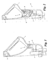
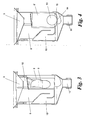
- the structure of the odor control valve 6 will be explained in more detail with reference to FIGS. 2 to 5.
- the Absaugsiphon 7 is in the example shown a so-called Spiralsiphon, i. a siphon having a helically curved flow channel which has a substantially constant or only slightly narrowing cross-section in order to achieve the suction effect known in the art, wherein each turn of the spiral forms a pipe elbow.
- Spiralsiphon i. a siphon having a helically curved flow channel which has a substantially constant or only slightly narrowing cross-section in order to achieve the suction effect known in the art, wherein each turn of the spiral forms a pipe elbow.
- the axis of the spiral is parallel and horizontal to the plane of the drawing.
- the siphoning siphon 7 is also of a standardized type, ie a standard siphon, which fulfills all regulatory requirements with regard to sewer gas closure, pressure fluctuations, flow cross-section and coking capacity for coarse contaminants. Regardless of the operating position of the odor control valve 6 thus all regulatory requirements for a proper Sewer gas seal already met by Absaugsiphon 7 alone.
- FIG. 2 shows a variant 5 'of the odor trap of FIG. 1.
- the odor trap 5' has a shunt connection 8 parallel to the odor control valve 6.
- the shunt connection 8 is capable of at least partially bridging the odor control valve 6 during the surge flushing operation, i. to establish a direct connection from drain 3 to suction siphon 7.
- the odor control valve 6 and shunt 8 assembly is shown in more detail in FIG.
- the odor control valve 6 is in this embodiment, a diaphragm valve with a tubular membrane 9 from a piece of flat tube which is forced through the top by entering liquid and these pass, but after the passage of the liquid closes again due to its elasticity to a repelling odor gases to prevent.
- the shunt 8 is a Moneloger flow channel which branches off laterally above the odor control valve 6, a small siphon 10 in the form of a chicane and at 11 - together with the output of the odor control valve 6 - to the Absaugsiphon 7 out.
- the diversion of the shunt connection 8 above the odor control valve 6 is achieved in the example shown in that the odor control valve 6 is located at a distance 12 below the outlet 3 of the urinal 1. Together with the fact that the flow resistance of the odor control valve 6 is greater than that of the shunt connection 8, this causes each rinsing process that the rinse water not only through the odor control valve 6, but also on this over the shunt connection 8 to Absaugsiphon 7 abrinnt. After Schwall Erasmusvorgang remains fresh water in the siphon 10 and thus closes the shunt connection 8 to smell from the Absaugsiphon 7, which is operated between the Schwall Anlagenvor réellen with urine.
- Fig. 4 shows an alternative embodiment with an odor control valve 6 '.
- the odor control valve 6 ' includes a float 13, which closes the drain opening 14 of a funnel 15 in the idle state.
- the float 13 Upon entry of liquid, the float 13 is first raised and thus releases the drain opening 14 to Absaugsiphon 7 back.
- Absaugsiphon 7 In a surge flushing in which a large amount of water impinges on the float 13 and this lapped around all sides, causes the pressure difference due to the lack of buoyancy at the location of the drain opening 14 that the buoyant body 13 is pressed down and the drain opening 14 closes; In this case, the entire rinse water is forwarded via the shunt connection 8 to Absaugsiphon 7.
- FIG. 5 shows a further variant 5 "of the odor trap with an odor control valve 6" which, as in FIG. 3, is designed as a diaphragm valve with a tubular membrane 9 and sits directly in a conical seat 16 of the outlet 3.
- the odor control valve 6 " With the aid of a lifting device 17, the odor control valve 6 "is lifted out of its seat 16 during the flushing operation, whereby the gap formed between the odor control valve 6" and the seat 16 forms the shunt connection 8. The majority of the rinse water flows through the shunt connection 8 directly to Absaugsiphon 7, while a part also flows through the odor control valve 6 ".
- an electromagnet 18 is arranged around the odor control valve 6 "which cooperates with a corresponding armature 19 arranged on the odor control valve 6".
Landscapes
- Engineering & Computer Science (AREA)
- Health & Medical Sciences (AREA)
- Life Sciences & Earth Sciences (AREA)
- Hydrology & Water Resources (AREA)
- Public Health (AREA)
- Water Supply & Treatment (AREA)
- Environmental & Geological Engineering (AREA)
- Sanitary Device For Flush Toilet (AREA)
Applications Claiming Priority (1)
| Application Number | Priority Date | Filing Date | Title |
|---|---|---|---|
| AT14432006A AT503554B1 (de) | 2006-08-30 | 2006-08-30 | Geruchsverschluss für den ablauf eines urinals |
Publications (2)
| Publication Number | Publication Date |
|---|---|
| EP1900883A2 true EP1900883A2 (fr) | 2008-03-19 |
| EP1900883A3 EP1900883A3 (fr) | 2009-08-12 |
Family
ID=38626606
Family Applications (1)
| Application Number | Title | Priority Date | Filing Date |
|---|---|---|---|
| EP07450140A Withdrawn EP1900883A3 (fr) | 2006-08-30 | 2007-08-20 | Piège à odeur d'une urinoir |
Country Status (2)
| Country | Link |
|---|---|
| EP (1) | EP1900883A3 (fr) |
| AT (1) | AT503554B1 (fr) |
Cited By (4)
| Publication number | Priority date | Publication date | Assignee | Title |
|---|---|---|---|---|
| EP2312066A1 (fr) * | 2009-10-06 | 2011-04-20 | Georg Hell | Urinoir sans eau |
| EP2568861A4 (fr) * | 2010-05-14 | 2014-12-17 | Karim Lagobi | Ensemble de blocage et d'écoulement permettant l'écoulement de déchets liquides tout en bloquant les odeurs |
| EP2412879B1 (fr) * | 2010-07-28 | 2018-02-14 | Andreas Bock | Urinoir et siphon pour urinoir |
| EP3540137A1 (fr) | 2018-03-13 | 2019-09-18 | Swiss Invent AG | Rinçage par flot avec plaque déflectrice |
Families Citing this family (2)
| Publication number | Priority date | Publication date | Assignee | Title |
|---|---|---|---|---|
| DE102011117750A1 (de) * | 2011-11-05 | 2013-05-08 | John Reese | Urinale |
| CN105421561B (zh) * | 2015-08-31 | 2018-09-11 | 徐旭东 | 一种立式节水小便池 |
Family Cites Families (3)
| Publication number | Priority date | Publication date | Assignee | Title |
|---|---|---|---|---|
| DE29803397U1 (de) * | 1998-02-26 | 1998-05-14 | Wang, Wen Hsing, Wuchi, Taichung | Strukturelle Verbesserung eines Geruchsstoppers für Abflußrohre |
| ATE263871T1 (de) * | 1998-05-05 | 2004-04-15 | Urimat Holding Ag | Geruchsverschluss für ein urinal |
| CH694274A5 (de) * | 2000-09-21 | 2004-10-29 | Urimat Holding Ag | Geruchsverschluss fuer ein Urinal. |
-
2006
- 2006-08-30 AT AT14432006A patent/AT503554B1/de not_active IP Right Cessation
-
2007
- 2007-08-20 EP EP07450140A patent/EP1900883A3/fr not_active Withdrawn
Cited By (5)
| Publication number | Priority date | Publication date | Assignee | Title |
|---|---|---|---|---|
| EP2312066A1 (fr) * | 2009-10-06 | 2011-04-20 | Georg Hell | Urinoir sans eau |
| EP2568861A4 (fr) * | 2010-05-14 | 2014-12-17 | Karim Lagobi | Ensemble de blocage et d'écoulement permettant l'écoulement de déchets liquides tout en bloquant les odeurs |
| EP2412879B1 (fr) * | 2010-07-28 | 2018-02-14 | Andreas Bock | Urinoir et siphon pour urinoir |
| EP3540137A1 (fr) | 2018-03-13 | 2019-09-18 | Swiss Invent AG | Rinçage par flot avec plaque déflectrice |
| DE102018105797A1 (de) | 2018-03-13 | 2019-09-19 | Swiss Invent Ag | Schwallspülung mit Umlenkplatte |
Also Published As
| Publication number | Publication date |
|---|---|
| AT503554B1 (de) | 2007-11-15 |
| EP1900883A3 (fr) | 2009-08-12 |
| AT503554A4 (de) | 2007-11-15 |
Similar Documents
| Publication | Publication Date | Title |
|---|---|---|
| EP2472014B1 (fr) | Installation sanitaire sans eau, siphon pour une telle installation et procédé de fonctionnement d'une telle installation | |
| DE102007061255A1 (de) | System zum Spülen einer Vakuumtoilette | |
| AT503554B1 (de) | Geruchsverschluss für den ablauf eines urinals | |
| DE102009010862B4 (de) | Geruchsverschluss für ein Vakuumtoilettenabflusssystem, Ablaufvorrichtung, Vakuumtoilettensystem sowie Flugzeug mit einem solchen Vakuumtoilettensystem | |
| EP2090701A1 (fr) | Urinoir doté d'un obturateur mécanique contre les odeurs | |
| EP2627835B1 (fr) | Urinoir et procédé de remplacement d'une fermeture anti-odeurs d'un urinoir | |
| EP1382758A2 (fr) | Urinoir | |
| EP1854926A1 (fr) | Dispositif d'écoulement pour réservoir de chasse d'eau | |
| EP4036326B1 (fr) | Système sanitaire et procédés de fabrication et d'utilisation de celui-ci | |
| DE102010033798B4 (de) | Einsatz für einen Siphon; Wasserlose Sanitäranlage; Verfahren zur Reinigung und Wartung einer wasserlosen Sanitäranlage; Verfahren zum Betrieb einer wasserlosen Sanitäranlage | |
| EP4242388A1 (fr) | Unité de dosage pour un réservoir de chasse d'eau et réservoir de chasse d'eau pour un dispositif sanitaire | |
| DE602004002213T2 (de) | System zur entfernung von gerüchen mit einem in einem flüssigkeitsbehälter enthaltenen ventil | |
| DE102006016030A1 (de) | System zum Spülen einer Vakuumtoilette | |
| DE102007004833A1 (de) | Verschlussvorrichtung für Vakuumurinale in Luftfahrzeugen | |
| EP1075572B1 (fr) | Cuvette de w.-c. | |
| EP0986679A1 (fr) | Systeme de toilettes a aspiration par le vide | |
| DE102020120913A1 (de) | Spülkasten für eine Sanitäreinrichtung | |
| EP4187028B1 (fr) | Dispositif de filtration pour un réservoir de chasse d'eau et réservoir de chasse d'eau pour un dispositif sanitaire | |
| WO2001053618A2 (fr) | Systeme sanitaire | |
| DE102011078884B4 (de) | Verschlusselement zum Verschließen eines Überlaufrohrs während der Geruchsabsaugung, Ablaufventil mit diesem Verschlusselement sowie Verwendung dieses Verschlusselements | |
| DE102009008574A1 (de) | Geruchsverschluss für ein Urinal | |
| EP0757135A1 (fr) | Réservoir de chasse d'eau | |
| DE69927952T2 (de) | Verbesserte vorrichtung und verfahren zum entfernen von toilettengerüchen | |
| DE7806058U1 (de) | Toiletten-Spülkasten für die Verwendung von Regen- und/oder Trinkwasser | |
| EP3421676B1 (fr) | Élément de siphon à installer dans un écoulement, en particulier dans un écoulement d'un urinoir sans eau |
Legal Events
| Date | Code | Title | Description |
|---|---|---|---|
| PUAI | Public reference made under article 153(3) epc to a published international application that has entered the european phase |
Free format text: ORIGINAL CODE: 0009012 |
|
| AK | Designated contracting states |
Kind code of ref document: A2 Designated state(s): AT BE BG CH CY CZ DE DK EE ES FI FR GB GR HU IE IS IT LI LT LU LV MC MT NL PL PT RO SE SI SK TR |
|
| AX | Request for extension of the european patent |
Extension state: AL BA HR MK YU |
|
| PUAL | Search report despatched |
Free format text: ORIGINAL CODE: 0009013 |
|
| AK | Designated contracting states |
Kind code of ref document: A3 Designated state(s): AT BE BG CH CY CZ DE DK EE ES FI FR GB GR HU IE IS IT LI LT LU LV MC MT NL PL PT RO SE SI SK TR |
|
| AX | Request for extension of the european patent |
Extension state: AL BA HR MK RS |
|
| AKX | Designation fees paid | ||
| REG | Reference to a national code |
Ref country code: DE Ref legal event code: 8566 |
|
| STAA | Information on the status of an ep patent application or granted ep patent |
Free format text: STATUS: THE APPLICATION IS DEEMED TO BE WITHDRAWN |
|
| 18D | Application deemed to be withdrawn |
Effective date: 20100213 |