EP1902680A1 - Verlängertes bioabsorbierbares Element - Google Patents
Verlängertes bioabsorbierbares Element Download PDFInfo
- Publication number
- EP1902680A1 EP1902680A1 EP07115585A EP07115585A EP1902680A1 EP 1902680 A1 EP1902680 A1 EP 1902680A1 EP 07115585 A EP07115585 A EP 07115585A EP 07115585 A EP07115585 A EP 07115585A EP 1902680 A1 EP1902680 A1 EP 1902680A1
- Authority
- EP
- European Patent Office
- Prior art keywords
- elongated member
- bioabsorbable
- bulge
- bioabsorbable elongated
- stopper
- Prior art date
- Legal status (The legal status is an assumption and is not a legal conclusion. Google has not performed a legal analysis and makes no representation as to the accuracy of the status listed.)
- Granted
Links
- 238000005452 bending Methods 0.000 claims abstract description 18
- 238000000034 method Methods 0.000 claims abstract description 16
- 230000000930 thermomechanical effect Effects 0.000 claims abstract description 4
- RKDVKSZUMVYZHH-UHFFFAOYSA-N 1,4-dioxane-2,5-dione Chemical compound O=C1COC(=O)CO1 RKDVKSZUMVYZHH-UHFFFAOYSA-N 0.000 claims description 4
- 238000010438 heat treatment Methods 0.000 claims description 4
- JJTUDXZGHPGLLC-UHFFFAOYSA-N lactide Chemical compound CC1OC(=O)C(C)OC1=O JJTUDXZGHPGLLC-UHFFFAOYSA-N 0.000 claims description 4
- 229920001577 copolymer Polymers 0.000 claims description 3
- 210000000988 bone and bone Anatomy 0.000 description 34
- 239000007943 implant Substances 0.000 description 21
- 208000010392 Bone Fractures Diseases 0.000 description 14
- 239000000463 material Substances 0.000 description 14
- 210000001519 tissue Anatomy 0.000 description 11
- 230000035876 healing Effects 0.000 description 8
- 210000002303 tibia Anatomy 0.000 description 7
- 238000011282 treatment Methods 0.000 description 7
- 206010017076 Fracture Diseases 0.000 description 6
- 239000000835 fiber Substances 0.000 description 4
- 230000002787 reinforcement Effects 0.000 description 4
- 230000001954 sterilising effect Effects 0.000 description 4
- 238000004659 sterilization and disinfection Methods 0.000 description 4
- 239000012634 fragment Substances 0.000 description 3
- 238000004519 manufacturing process Methods 0.000 description 3
- 229920000642 polymer Polymers 0.000 description 3
- 239000007787 solid Substances 0.000 description 3
- 239000000126 substance Substances 0.000 description 3
- 208000003076 Osteolysis Diseases 0.000 description 2
- 239000003242 anti bacterial agent Substances 0.000 description 2
- 229940088710 antibiotic agent Drugs 0.000 description 2
- 230000008901 benefit Effects 0.000 description 2
- 230000000975 bioactive effect Effects 0.000 description 2
- 239000000919 ceramic Substances 0.000 description 2
- 238000005520 cutting process Methods 0.000 description 2
- 230000003111 delayed effect Effects 0.000 description 2
- 239000012467 final product Substances 0.000 description 2
- 238000011065 in-situ storage Methods 0.000 description 2
- 208000029791 lytic metastatic bone lesion Diseases 0.000 description 2
- 230000005012 migration Effects 0.000 description 2
- 238000013508 migration Methods 0.000 description 2
- 238000000465 moulding Methods 0.000 description 2
- 230000017074 necrotic cell death Effects 0.000 description 2
- 230000000149 penetrating effect Effects 0.000 description 2
- 238000003825 pressing Methods 0.000 description 2
- GUTLYIVDDKVIGB-OUBTZVSYSA-N Cobalt-60 Chemical compound [60Co] GUTLYIVDDKVIGB-OUBTZVSYSA-N 0.000 description 1
- 208000024779 Comminuted Fractures Diseases 0.000 description 1
- 206010010149 Complicated fracture Diseases 0.000 description 1
- 241001269524 Dura Species 0.000 description 1
- IAYPIBMASNFSPL-UHFFFAOYSA-N Ethylene oxide Chemical compound C1CO1 IAYPIBMASNFSPL-UHFFFAOYSA-N 0.000 description 1
- 206010028851 Necrosis Diseases 0.000 description 1
- 206010031264 Osteonecrosis Diseases 0.000 description 1
- 206010034122 Patella fracture Diseases 0.000 description 1
- 208000002607 Pseudarthrosis Diseases 0.000 description 1
- 208000027418 Wounds and injury Diseases 0.000 description 1
- 230000002411 adverse Effects 0.000 description 1
- 239000000956 alloy Substances 0.000 description 1
- 229910045601 alloy Inorganic materials 0.000 description 1
- 239000005313 bioactive glass Substances 0.000 description 1
- 239000004621 biodegradable polymer Substances 0.000 description 1
- 229920002988 biodegradable polymer Polymers 0.000 description 1
- 230000015572 biosynthetic process Effects 0.000 description 1
- 239000001506 calcium phosphate Substances 0.000 description 1
- 230000000973 chemotherapeutic effect Effects 0.000 description 1
- 239000011247 coating layer Substances 0.000 description 1
- 239000002131 composite material Substances 0.000 description 1
- 238000001816 cooling Methods 0.000 description 1
- 238000002316 cosmetic surgery Methods 0.000 description 1
- 238000005553 drilling Methods 0.000 description 1
- 239000003814 drug Substances 0.000 description 1
- 229940079593 drug Drugs 0.000 description 1
- 230000001700 effect on tissue Effects 0.000 description 1
- 238000010894 electron beam technology Methods 0.000 description 1
- 238000005516 engineering process Methods 0.000 description 1
- 238000001125 extrusion Methods 0.000 description 1
- 239000003102 growth factor Substances 0.000 description 1
- 239000005556 hormone Substances 0.000 description 1
- 229940088597 hormone Drugs 0.000 description 1
- 210000002758 humerus Anatomy 0.000 description 1
- 229910052588 hydroxylapatite Inorganic materials 0.000 description 1
- 208000015181 infectious disease Diseases 0.000 description 1
- 238000001746 injection moulding Methods 0.000 description 1
- 208000014674 injury Diseases 0.000 description 1
- 210000002414 leg Anatomy 0.000 description 1
- 230000003902 lesion Effects 0.000 description 1
- 238000003754 machining Methods 0.000 description 1
- 239000011159 matrix material Substances 0.000 description 1
- 239000000155 melt Substances 0.000 description 1
- 239000002184 metal Substances 0.000 description 1
- 229910052751 metal Inorganic materials 0.000 description 1
- 238000002324 minimally invasive surgery Methods 0.000 description 1
- 238000012986 modification Methods 0.000 description 1
- 230000004048 modification Effects 0.000 description 1
- 230000000921 morphogenic effect Effects 0.000 description 1
- 206010033675 panniculitis Diseases 0.000 description 1
- XYJRXVWERLGGKC-UHFFFAOYSA-D pentacalcium;hydroxide;triphosphate Chemical compound [OH-].[Ca+2].[Ca+2].[Ca+2].[Ca+2].[Ca+2].[O-]P([O-])([O-])=O.[O-]P([O-])([O-])=O.[O-]P([O-])([O-])=O XYJRXVWERLGGKC-UHFFFAOYSA-D 0.000 description 1
- 229920002959 polymer blend Polymers 0.000 description 1
- 102000004169 proteins and genes Human genes 0.000 description 1
- 108090000623 proteins and genes Proteins 0.000 description 1
- 230000005855 radiation Effects 0.000 description 1
- 230000003014 reinforcing effect Effects 0.000 description 1
- 239000012783 reinforcing fiber Substances 0.000 description 1
- 230000000717 retained effect Effects 0.000 description 1
- 239000011265 semifinished product Substances 0.000 description 1
- 238000005245 sintering Methods 0.000 description 1
- 239000011343 solid material Substances 0.000 description 1
- 239000010935 stainless steel Substances 0.000 description 1
- 229910001220 stainless steel Inorganic materials 0.000 description 1
- 210000001562 sternum Anatomy 0.000 description 1
- 210000004304 subcutaneous tissue Anatomy 0.000 description 1
- 238000001356 surgical procedure Methods 0.000 description 1
- 238000003856 thermoforming Methods 0.000 description 1
- 206010043827 tibia fracture Diseases 0.000 description 1
- 230000008733 trauma Effects 0.000 description 1
- QORWJWZARLRLPR-UHFFFAOYSA-H tricalcium bis(phosphate) Chemical compound [Ca+2].[Ca+2].[Ca+2].[O-]P([O-])([O-])=O.[O-]P([O-])([O-])=O QORWJWZARLRLPR-UHFFFAOYSA-H 0.000 description 1
- 229940078499 tricalcium phosphate Drugs 0.000 description 1
- 229910000391 tricalcium phosphate Inorganic materials 0.000 description 1
- 235000019731 tricalcium phosphate Nutrition 0.000 description 1
- 238000007514 turning Methods 0.000 description 1
- 208000017013 ulna fracture Diseases 0.000 description 1
- 238000004804 winding Methods 0.000 description 1
Images









Classifications
-
- A—HUMAN NECESSITIES
- A61—MEDICAL OR VETERINARY SCIENCE; HYGIENE
- A61B—DIAGNOSIS; SURGERY; IDENTIFICATION
- A61B17/00—Surgical instruments, devices or methods
- A61B17/56—Surgical instruments or methods for treatment of bones or joints; Devices specially adapted therefor
- A61B17/58—Surgical instruments or methods for treatment of bones or joints; Devices specially adapted therefor for osteosynthesis, e.g. bone plates, screws or setting implements
- A61B17/68—Internal fixation devices, including fasteners and spinal fixators, even if a part thereof projects from the skin
-
- A—HUMAN NECESSITIES
- A61—MEDICAL OR VETERINARY SCIENCE; HYGIENE
- A61B—DIAGNOSIS; SURGERY; IDENTIFICATION
- A61B17/00—Surgical instruments, devices or methods
- A61B17/56—Surgical instruments or methods for treatment of bones or joints; Devices specially adapted therefor
- A61B17/58—Surgical instruments or methods for treatment of bones or joints; Devices specially adapted therefor for osteosynthesis, e.g. bone plates, screws or setting implements
- A61B17/68—Internal fixation devices, including fasteners and spinal fixators, even if a part thereof projects from the skin
- A61B17/82—Internal fixation devices, including fasteners and spinal fixators, even if a part thereof projects from the skin for bone cerclage
-
- A—HUMAN NECESSITIES
- A61—MEDICAL OR VETERINARY SCIENCE; HYGIENE
- A61B—DIAGNOSIS; SURGERY; IDENTIFICATION
- A61B17/00—Surgical instruments, devices or methods
- A61B17/56—Surgical instruments or methods for treatment of bones or joints; Devices specially adapted therefor
- A61B17/58—Surgical instruments or methods for treatment of bones or joints; Devices specially adapted therefor for osteosynthesis, e.g. bone plates, screws or setting implements
- A61B17/68—Internal fixation devices, including fasteners and spinal fixators, even if a part thereof projects from the skin
- A61B17/84—Fasteners therefor or fasteners being internal fixation devices
- A61B17/846—Nails or pins, i.e. anchors without movable parts, holding by friction only, with or without structured surface
- A61B17/848—Kirschner wires, i.e. thin, long nails
-
- A—HUMAN NECESSITIES
- A61—MEDICAL OR VETERINARY SCIENCE; HYGIENE
- A61B—DIAGNOSIS; SURGERY; IDENTIFICATION
- A61B17/00—Surgical instruments, devices or methods
- A61B2017/00004—(bio)absorbable, (bio)resorbable or resorptive
-
- A—HUMAN NECESSITIES
- A61—MEDICAL OR VETERINARY SCIENCE; HYGIENE
- A61B—DIAGNOSIS; SURGERY; IDENTIFICATION
- A61B17/00—Surgical instruments, devices or methods
- A61B17/04—Surgical instruments, devices or methods for suturing wounds; Holders or packages for needles or suture materials
- A61B17/06—Needles ; Sutures; Needle-suture combinations; Holders or packages for needles or suture materials
- A61B17/06166—Sutures
- A61B2017/06176—Sutures with protrusions, e.g. barbs
-
- A—HUMAN NECESSITIES
- A61—MEDICAL OR VETERINARY SCIENCE; HYGIENE
- A61B—DIAGNOSIS; SURGERY; IDENTIFICATION
- A61B17/00—Surgical instruments, devices or methods
- A61B17/04—Surgical instruments, devices or methods for suturing wounds; Holders or packages for needles or suture materials
- A61B17/06—Needles ; Sutures; Needle-suture combinations; Holders or packages for needles or suture materials
- A61B17/06166—Sutures
- A61B2017/0619—Sutures thermoplastic, e.g. for bonding, welding, fusing or cutting the suture by melting it
Definitions
- the present invention relates to a bioabsorbable elongated member which may be used in a bone and/or tissue fixation.
- tension band wires In bone surgery it is well known to use metallic tension band wires in the internal fixation of bone fractures, osteotomies and pseudarthroses.
- a typical tension band wire is a flexible metallic wire with a diameter of about 1 mm.
- the clinical use of tension band wires is described e.g. in M.E. Müller et al., “Manual of Internal Fixation", Springen-Verlag, Berlin Heidelberg New York, 1979, pages 42-47 .
- tension band wiring has several drawbacks. Because of the high tensile modulus of metallic wires, the tightening of wire too much can lead to bone fractures or to necrosis under the wire. Also the knotting of the wire loop creates a bulky knot which can irritate tissues, especially subcutaneous tissue on a bone, which can lead even to an infection and/or sinus formation.
- locking members and systems are e.g. crimps (e.g. US Pat. No. 5,536,270 , US Pat. No. 5,649,927 ), connectors ( US Pat. No. 5,415,658 ), cable ties ( US Pat. No. Des. 369,960 , US Pat. No, 3,886,630 ), loop locking structures ( US Pat. No. 4,813,416 ), suture locks ( US Pat. No. 5,364,407 ), clamps ( US Pat. No. 4,201,215 ), buckles ( US Pat. No. 5,355,913 ) and locking systems comprising bioabsorbable fasteners ( US Pat. Appl. No. 10/657,087 ).
- crimps e.g. US Pat. No. 5,536,270 , US Pat. No. 5,649,927
- connectors US Pat. No. 5,415,658
- cable ties US Pat. No. Des. 369,960 , US Pat. No, 3,886,630
- the present invention provides a bioabsorbable elongated member which provides accurate tensioning of the band and safe locking of the band around and/or inside of the bone by means of minimally invasive surgery.
- the present invention also provides a bioabsorbable elongated member which is simple, easy to make and rapid and easy to use surgically.
- the present invention also provides a bioabsorbable elongated member which is small but creates a secure locking of the member and fixed bone fragments.
- the orientation of the elongated member of the invention is locally alterable, usually the elongated member is radially expandable.
- the radial expansion is a consequence of the microstructure of the implant of the invention.
- At least a part of the elongated member is constructed of a material having uniaxial, longitudinal stresses, formed therein by solid state drawing or pullforming. Multiaxial stresses are also possible. The multiaxial stresses are created for example by turning spirally a blank of the elongated member. These stresses in the material, when treated mechanically (such as by locally moving around and bending), thermally or thermomechanically, are relieved, whereby a radial, local expansion of the material takes place, thus creating a bulge.
- the property of creating the bulge can be identified simply by bending the bioabsorbable elongated member by hand repeatedly at the same point.
- the material of the bioabsorbable elongated member heats up due to the internal friction while it is bent. After a few bends, the bulge forms due to the relaxation of the material.
- the bioabsorbable elongated member can be bent at the bulge in a desired direction, or the bulge can be left as such in order to form a local stopper, or a part of a local stopper. It is naturally also possible to move the elongated member in other ways than by bending; all mechanical treatments, for example rotating, having the same result, i.e. the bulge, are usable as well.
- the main benefit of the mechanical treatment compared to the other possible methods is that the bulge can be formed in-situ during a surgical operation without special tools, i.e. one can freely decide where to form the bulge, and it can be done by hand simply for example by bending the elongated member back and forth at the same point.
- the bulge may be used as a stopper, a part of a stopper, or a bending point of a bioabsorbable member.
- the bulge may be used instead of knots, or other stoppers or locking members.
- the other possible methods for forming a bulge include thermal or thermomechanical treatments.
- such treatments require a tool for forming the bulge.
- the tool may be a heating device, or a device which combines heating and mechanical treatment, such as heatable pliers.
- a bioabsorbable member for securing a bone fracture, or bone fractures comprising a first end, an elongated part and a second end.
- the elongated part may be flexible or rigid.
- the bioabsorbable member can be locally expanded radially by means of mechanical or thermal or thermomechanical treatment. The mechanical treatment is preferred.
- a method to secure bone fracture(s) or osteotomy (osteotomies) with a bioabsorbable elongated member includes (a) the radial expansion of a part of a first end part to create a first locking member (local enlargement of the first end part), (b) pushing a second end part (equipped with an optional needle) and a shaft part into and through drill hole(s) in bone fragment(s), (c) tightening the elongated member by pulling the second end part which is outside of bone after pushing through drill hole(s) and (d) the local radial expansion of the second end part under tension just on the opening of the drill hole from which the second end part emerges, in order to create a second locking member (local enlargement of the second end part) and (e) cutting of the first end part and second end part so that the first locking member remains in the entrance opening of the first drill hole and the second locking member remains on the outlet of the last drill hole.
- a method to secure a bone fracture or osteotomy with a bioabsorbable elongated member includes (a) passing the second end part (optionally equipped with a needle) around the bony tissues to be drawn together, (b) pulling the second end part through a hole in the (optionally flattened) part of the first end part (now the first locking element), (c) tightening the elongated member by keeping the first end part in place and pulling the second end part to a proper tension, (d) expanding locally and radially the second end part under tension to create the second locking element (local enlargement of the second end part) just outside of the outlet of the hole in the first locking element, and (e) cutting the second end part so that the second locking element secures the closing of the band loop surrounding the bony tissues fixed together.
- the bioabsorbable implants (bioabsorbable bands or rods) of this invention may be manufactured of bioabsorbable polymers, copolymers or polymer mixtures or alloys.
- the preferred material is a copolymer of lactide and glycolide.
- the material may comprise 70 to 85 wt.-% lactide and 15 to 30 wt.-% glycolide.
- Suitable manufacturing methods include molding, sintering and/or solid state deformation (pullforming) methods which are described e.g. in US Pat. No. 4,743,257 , US Pat. No. 4,968,317 , EP Pat. No. 0423155 , AU Pat. No. 729801 , EP Pat. No. 1009448 and in US Pat. No. 6,406,598 .
- the strong and tough oriented structures are especially advantageous in implant systems of this invention. They may be created also during extrusion or injection molding of absorbable polymeric melt through a suitable die or into a suitable mold at high speed and pressure. When cooling occurs at suitable conditions, the flow orientation of the melt may remain in the solid material as an oriented structure.
- the mold may have the form of the final device, but it is also possible to manufacture the implants of the invention by machining (possibly using also heat) and by thermoforming of injection-molded or extruded semi-finished products.
- the reinforcing fibers of the implants may also be ceramic fibers, such as bioabsorbable hydroxyapatite or bioactive glass or tricalcium phosphate fibers.
- ceramic fibers such as bioabsorbable hydroxyapatite or bioactive glass or tricalcium phosphate fibers.
- bioabsorbable, ceramic fiber reinforced materials are described e.g. in European Patent Application No. 0146398 and in WO 96/21628 .
- the oriented and/or fiber reinforced implants of this invention may be manufactured by molding the reinforcement fiber-polymer matrix to the final product in a mold whose mold cavity has the form of the final product, or the final form may be machined mechanically (possibly also using heat) of a preform, such as a melt-molded and solid-state drawn rod, as described e.g. in United States Patent No. 4,968,317 .
- the reinforcement elements may extend into any protrusions or ridges of the implant.
- the reinforcement elements may also turn spirally around the longitudinal axis of the implants.
- other different orientations of reinforcement elements in elongated samples which are known in composite technology may be applied to the present invention.
- a general feature of the orientation and/or fiber-reinforcement of the implants of this invention is that many of the reinforcing elements are oriented in such a way that they can carry effectively the different external loads (such as tensile, bending and shear loads) that are directed to the healing bone fracture or osteotomy, e.g. sternotomy.
- the implant may contain one or more bioactive substances, such as antibiotics, chemotherapeutic substances, growth factors such as bone morphogenic proteins, substances accelerating the healing of the wound and osteotomy, hormones, antibiotics or other drugs and the like.
- bioactive substances such as antibiotics, chemotherapeutic substances, growth factors such as bone morphogenic proteins, substances accelerating the healing of the wound and osteotomy, hormones, antibiotics or other drugs and the like.
- bioactive implants are especially advantageous in surgical use, because they contribute biochemically to the healing of the lesion in addition to providing mechanical support.
- the oriented and/or reinforced materials of the implants of this invention typically have initial tensile strengths of about 100 to 1000 MPa, bending strengths of about 100 to 500 MPa and shear strengths of about 80 to 300 MPa.
- the implants can be made stiff, tough, and/or flexible. These mechanical properties are superior to those of non-oriented and non-reinforced absorbable polymers which typically show strengths between 40 and 100 MPa and may additionally be brittle (see e.g. S. Vainion university, P. Rokkanen and P. Törmälä, "Surgical Applications of Biodegradable Polymers in Human Tissues", Progr. Polym. Sci 14/1989, pp. 679-716 ).
- a special advantage of the present invention is that there are no bulky crimps in these implants. They can be made relatively thin e.g. with a cylindrical shaft part having a diameter between 0.5 and 4 mm and a bulge having a diameter between 1 and 8 mm.
- the implants of the present invention may be sterilized by any of the well known sterilization techniques, depending on the type of material used in manufacture of the implant. Suitable sterilization techniques include radiation sterilization such as cobalt 60 irradiation or electron beams, ethylene oxide sterilization, and the like.
- the elongated member may be provided with at least one needle.
- the needle there may also be a drill bit or a kirschner wire by which a drillhole can be drilled into a bone.
- the possible uses of the elongated member comprise, for example, olecranon fractures, patella fractures, tuberculum majus fractures of proximal humerus, comminuted fractures of distal tibia (also syndesmosis) and comminuted proximal tibia fractures.
- the elongated member can be used for the fixation of bone containing a latissimus dorsi graft.
- the elongated member may be used in combination with other pins and screws.
- Figs. 1 b, 1 c, 9e - 9i, 12b show a bone to be fixed.
- a person skilled in the art will readily understand how the bone or tissue exists with respect to an elongated member in other figures.
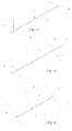
- Fig. 1 a shows a bioabsorbable elongated member which is a rod comprising a shaft 1.
- the cross-section of the rod may be cylindrical, square or any other suitable cross-section.
- the shaft 1 comprises a first end 2 and a second end 3 and an elongated part 4 therebetween. Needles 5 assisting in penetrating into a bone or tissue are attached to the both ends 2, 3 of the shaft 1. It is also possible that there is only one needle in one end of the shaft 1.
- the rod is delivered to its user as it is illustrated in Fig. 1 a.
- Fig. 1 b shows the bioabsorbable elongated member, i.e. the rod of Fig. 1 a, in such a situation in which the user has inserted the rod in a drillhole in a broken bone 7 (number 8 denotes the fracture) and he has formed two bulges 6 in the shaft 1. Providing both ends with needles 5 makes it easier to fix rather complicated fractures.
- Fig. 1 c shows the rod of Figs. 1 a and 1 b when the excess of the shaft 1 has been cut off.
- Fig. 2a shows a rod comprising a shaft 1 and a head 9.
- the head 9 is formed by pressing down.
- the rod is delivered to its user as it is illustrated in Fig. 2a.
- Fig. 2b shows a situation in which the rod is inserted in a drillhole in a broken bone 7 (not shown).
- a bulge 6 forming a stopper is formed at the end of the shaft 1.
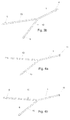
- Fig. 3a shows an elongated member whose shaft 1 comprises branches 10.
- the branches 10 of the elongated member may be inserted in drillholes in a broken bone. After the branches have been positioned, bulges 6 are formed outside the bone 7 (not shown) as shown in Fig. 3b.
- Fig. 4 shows another variation of the elongated member of Fig. 3.
- the elongated member comprises a pre-manufactured head 11 which may be manufactured by pressing down.
- Branches 10 are inserted in a drillhole in a bone and bulges 6 are formed in the branches.
- Figs. 5 and 6 also show branched elongated members.
- Figs. 5a and 6a show the elongated members before implanting
- Figs. 5b and 6b show the elongated members after implanting.
- Bulges 6 are formed in each branch.
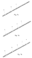
- Fig. 7a shows an elongated member, such as a pin which has a grooved surface.
- Fig. 7a also shows a first end 2, a second end 3, a front end 2a, a back end 3a and a target point T.
- the front end 2a begins from the first end 2 and terminates at the target point T.
- the back end 3a begins from the target point T and terminates at the second end 3.
- a bulge 6 is formed at the target point T.
- Figs. 7b to 7e show that in principle a bulge 6 can be formed in the pin wherever desired, i.e. there can be several target points T.
- Fig. 8a shows an elongated member whose outer appearance resembles a cable tie.
- the elongated member has a flexible band section 12.
- the elongated member also comprises in its one end an eyelet 13 in which the other end can be threaded, as shown in Fig. 8b.
- a bulge 6 is formed outside the eyelet.
- the bulge forms a stopper as shown in Fig. 8c.
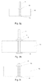
- Fig. 9 shows an elongated member which is used e.g. in applications in which the cranium is fixed.
- the elongated member comprises a shaft 1 and a head 14.
- the shaft 1 of the elongated member is inserted through a drillhole in the cranium so that the head 14 of the elongated member is left under the cranium but over the dura.
- the head of the elongated member is a flat round plate as is natural due to the application.
- the diameter of the round plate may be at least 10 mm.
- the diameter of the shaft 1 may be around 10 mm.
- Fig. 9j shows the cranium, which is fixed with the elongated members, from above.
- a piece of the cranial bone 16b has been separated from the rest of the cranium 16a in order to make surgical operations.
- the elongated members are fastened at the edge of the piece of the cranial bone 16b.
- Bulges are formed on the elongated member so that they keep the piece of the cranial bone 16b in its position (see Fig. 9i).
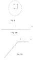
- Fig. 10 shows an elongated member which is useful in applications in which the elongated member shall change its advancing direction.
- the elongated member may comprise a prefabricated head, or the head may be formed in situ.
- the advancing direction of the elongated member may be changed as desired as shown in Figs. 10 b and 10c by mechanically straining a certain point of the elongated member.
- Fig. 10d shows a situation in which a desired length of the elongated member is used for the fixation and a bulge is formed at the end of the elongated member.
- the bulge 6 increases the strength of the elongated member in its bending direction.
- Fig. 11 shows variations of head designs of an elongated member.
- Fig. 11 a shows a spherical head
- Fig. 11 b shows a flat round head
- Fig. 11c shows a spherical head whose joint with the shaft has been made gentle
- Fig. 11 d shows a truncated spherical head whose joint with the shaft has been made gentle.
- Fig. 12a shows fractures 8 in the distal end of tibia 17.
- Fig. 12b shows how the fractures 8 have been fixed with elongated members 18 and 19.
- the elongated member 18 is a pin which has been inserted in drillholes penetrating through the tibia 17.
- the elongated member 19 is a rod which has been inserted in a drillhole and whose advancing direction has been changed by forming bulges 6 outside the tibia 17.
- the tibia is an example about possible targets of the elongated member.
- the principle of fixation is also the same with fractures in other bones:
- the elongated member is inserted in a drillhole or drillholes in a bone, and bulges are formed in the elongated member outside the bone in order to use them as stoppers or bending points.
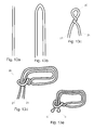
- Figs. 13a to 13e show one possible way to form a loop 20 from an elongated member.
- the straight elongated member of Fig. 13a is bent (Fig. 13b) and twisted (Fig. 13c) so that the loop 20 and two elongated tails 21 are formed.
- the legs 21 of the elongated member are threaded into the loop 20 (Fig. 13d).
- Bulges 6 are formed on the tails 21, and the tails 21 are cut underneath the bulges 6. The bulges 6 prevent the tails 21 from slipping out the loop 20.
- Figs. 14a to 14c show an elongated member with a retaining plate 22. It is possible to form a bulge 6 on the elongated member before inserting the elongated member into a bone and/or tissue, or the bulge 6 can be formed after inserting the elongated member.
- the elongated member may be provided with a needle 5. After the elongated member has been inserted it forms either a loop around the bone and/or tissue, or it has been inserted in a drillhole or drillholes in the bone. It can be used for example for the fixation of the sternum.
- the ends of the elongated member are threaded through holes 23 in the retaining plate 22 and they are provided with the bulges 6. The elongated member is cut from the side of the bulge 6.
- the retaining plate 22 secures that the bulges 6 are prevented from slipping out from their position.
- Fig. 15 shows elongated members which are used with cannulated screws 24 and a retaining plate 22.
- the cannulated screws 24 have been inserted in a bone and the elongated members are inserted via drillholes through the cannulated screws 24 and holes in the retaining plate 22.
- the ends of the elongated members are provided with bulges 6 which act as local stoppers.
- the cannulated screws 24 and the retaining plate 22 secures that the bulges 6 do not slip into the drillholes.
Landscapes
- Health & Medical Sciences (AREA)
- Orthopedic Medicine & Surgery (AREA)
- Surgery (AREA)
- Life Sciences & Earth Sciences (AREA)
- Heart & Thoracic Surgery (AREA)
- Animal Behavior & Ethology (AREA)
- Engineering & Computer Science (AREA)
- Biomedical Technology (AREA)
- Neurology (AREA)
- Medical Informatics (AREA)
- Molecular Biology (AREA)
- Nuclear Medicine, Radiotherapy & Molecular Imaging (AREA)
- General Health & Medical Sciences (AREA)
- Public Health (AREA)
- Veterinary Medicine (AREA)
- Surgical Instruments (AREA)
- Prostheses (AREA)
- Materials For Medical Uses (AREA)
- Organic Low-Molecular-Weight Compounds And Preparation Thereof (AREA)
Applications Claiming Priority (1)
| Application Number | Priority Date | Filing Date | Title |
|---|---|---|---|
| FI20065574A FI120963B (fi) | 2006-09-20 | 2006-09-20 | Bioabsorboituva pitkänomainen elin |
Publications (2)
| Publication Number | Publication Date |
|---|---|
| EP1902680A1 true EP1902680A1 (de) | 2008-03-26 |
| EP1902680B1 EP1902680B1 (de) | 2010-11-10 |
Family
ID=37067225
Family Applications (1)
| Application Number | Title | Priority Date | Filing Date |
|---|---|---|---|
| EP07115585A Not-in-force EP1902680B1 (de) | 2006-09-20 | 2007-09-04 | Verlängertes bioabsorbierbares Element |
Country Status (5)
| Country | Link |
|---|---|
| US (1) | US20080071299A1 (de) |
| EP (1) | EP1902680B1 (de) |
| AT (1) | ATE487431T1 (de) |
| DE (1) | DE602007010394D1 (de) |
| FI (1) | FI120963B (de) |
Families Citing this family (68)
| Publication number | Priority date | Publication date | Assignee | Title |
|---|---|---|---|---|
| US7601165B2 (en) | 2006-09-29 | 2009-10-13 | Biomet Sports Medicine, Llc | Method and apparatus for forming a self-locking adjustable suture loop |
| US8088130B2 (en) | 2006-02-03 | 2012-01-03 | Biomet Sports Medicine, Llc | Method and apparatus for coupling soft tissue to a bone |
| US8361113B2 (en) | 2006-02-03 | 2013-01-29 | Biomet Sports Medicine, Llc | Method and apparatus for coupling soft tissue to a bone |
| US7905904B2 (en) | 2006-02-03 | 2011-03-15 | Biomet Sports Medicine, Llc | Soft tissue repair device and associated methods |
| US8137382B2 (en) | 2004-11-05 | 2012-03-20 | Biomet Sports Medicine, Llc | Method and apparatus for coupling anatomical features |
| US8840645B2 (en) | 2004-11-05 | 2014-09-23 | Biomet Sports Medicine, Llc | Method and apparatus for coupling soft tissue to a bone |
| US8128658B2 (en) | 2004-11-05 | 2012-03-06 | Biomet Sports Medicine, Llc | Method and apparatus for coupling soft tissue to bone |
| US7857830B2 (en) * | 2006-02-03 | 2010-12-28 | Biomet Sports Medicine, Llc | Soft tissue repair and conduit device |
| US7909851B2 (en) | 2006-02-03 | 2011-03-22 | Biomet Sports Medicine, Llc | Soft tissue repair device and associated methods |
| US8298262B2 (en) | 2006-02-03 | 2012-10-30 | Biomet Sports Medicine, Llc | Method for tissue fixation |
| US9801708B2 (en) | 2004-11-05 | 2017-10-31 | Biomet Sports Medicine, Llc | Method and apparatus for coupling soft tissue to a bone |
| US8118836B2 (en) | 2004-11-05 | 2012-02-21 | Biomet Sports Medicine, Llc | Method and apparatus for coupling soft tissue to a bone |
| US8303604B2 (en) | 2004-11-05 | 2012-11-06 | Biomet Sports Medicine, Llc | Soft tissue repair device and method |
| US7749250B2 (en) | 2006-02-03 | 2010-07-06 | Biomet Sports Medicine, Llc | Soft tissue repair assembly and associated method |
| US9017381B2 (en) | 2007-04-10 | 2015-04-28 | Biomet Sports Medicine, Llc | Adjustable knotless loops |
| US8998949B2 (en) | 2004-11-09 | 2015-04-07 | Biomet Sports Medicine, Llc | Soft tissue conduit device |
| US8771352B2 (en) | 2011-05-17 | 2014-07-08 | Biomet Sports Medicine, Llc | Method and apparatus for tibial fixation of an ACL graft |
| US8574235B2 (en) * | 2006-02-03 | 2013-11-05 | Biomet Sports Medicine, Llc | Method for trochanteric reattachment |
| US8251998B2 (en) | 2006-08-16 | 2012-08-28 | Biomet Sports Medicine, Llc | Chondral defect repair |
| US8597327B2 (en) | 2006-02-03 | 2013-12-03 | Biomet Manufacturing, Llc | Method and apparatus for sternal closure |
| US9271713B2 (en) | 2006-02-03 | 2016-03-01 | Biomet Sports Medicine, Llc | Method and apparatus for tensioning a suture |
| US8968364B2 (en) | 2006-02-03 | 2015-03-03 | Biomet Sports Medicine, Llc | Method and apparatus for fixation of an ACL graft |
| US9538998B2 (en) | 2006-02-03 | 2017-01-10 | Biomet Sports Medicine, Llc | Method and apparatus for fracture fixation |
| US8562647B2 (en) | 2006-09-29 | 2013-10-22 | Biomet Sports Medicine, Llc | Method and apparatus for securing soft tissue to bone |
| US9468433B2 (en) | 2006-02-03 | 2016-10-18 | Biomet Sports Medicine, Llc | Method and apparatus for forming a self-locking adjustable loop |
| US8652172B2 (en) | 2006-02-03 | 2014-02-18 | Biomet Sports Medicine, Llc | Flexible anchors for tissue fixation |
| US8562645B2 (en) | 2006-09-29 | 2013-10-22 | Biomet Sports Medicine, Llc | Method and apparatus for forming a self-locking adjustable loop |
| US8801783B2 (en) | 2006-09-29 | 2014-08-12 | Biomet Sports Medicine, Llc | Prosthetic ligament system for knee joint |
| US11311287B2 (en) | 2006-02-03 | 2022-04-26 | Biomet Sports Medicine, Llc | Method for tissue fixation |
| US9078644B2 (en) | 2006-09-29 | 2015-07-14 | Biomet Sports Medicine, Llc | Fracture fixation device |
| US8506597B2 (en) | 2011-10-25 | 2013-08-13 | Biomet Sports Medicine, Llc | Method and apparatus for interosseous membrane reconstruction |
| US9149267B2 (en) | 2006-02-03 | 2015-10-06 | Biomet Sports Medicine, Llc | Method and apparatus for coupling soft tissue to a bone |
| US10517587B2 (en) | 2006-02-03 | 2019-12-31 | Biomet Sports Medicine, Llc | Method and apparatus for forming a self-locking adjustable loop |
| US8652171B2 (en) * | 2006-02-03 | 2014-02-18 | Biomet Sports Medicine, Llc | Method and apparatus for soft tissue fixation |
| US11259792B2 (en) | 2006-02-03 | 2022-03-01 | Biomet Sports Medicine, Llc | Method and apparatus for coupling anatomical features |
| US8672969B2 (en) | 2006-09-29 | 2014-03-18 | Biomet Sports Medicine, Llc | Fracture fixation device |
| US8500818B2 (en) | 2006-09-29 | 2013-08-06 | Biomet Manufacturing, Llc | Knee prosthesis assembly with ligament link |
| US9918826B2 (en) | 2006-09-29 | 2018-03-20 | Biomet Sports Medicine, Llc | Scaffold for spring ligament repair |
| US11259794B2 (en) | 2006-09-29 | 2022-03-01 | Biomet Sports Medicine, Llc | Method for implanting soft tissue |
| US12502169B2 (en) | 2007-01-16 | 2025-12-23 | Biomet Sports Medicine, Llc | Soft tissue repair device and associated methods |
| KR101271960B1 (ko) * | 2008-08-18 | 2013-06-07 | 키옵티크 포토닉스 게엠베하 운트 콤파니 카게 | 대물렌즈 제조 방법 |
| US12419632B2 (en) | 2008-08-22 | 2025-09-23 | Biomet Sports Medicine, Llc | Method and apparatus for coupling anatomical features |
| US12245759B2 (en) | 2008-08-22 | 2025-03-11 | Biomet Sports Medicine, Llc | Method and apparatus for coupling soft tissue to bone |
| US8343227B2 (en) | 2009-05-28 | 2013-01-01 | Biomet Manufacturing Corp. | Knee prosthesis assembly with ligament link |
| US12096928B2 (en) | 2009-05-29 | 2024-09-24 | Biomet Sports Medicine, Llc | Method and apparatus for coupling soft tissue to a bone |
| US12551209B2 (en) | 2009-06-22 | 2026-02-17 | Biomet Sports Medicine, Llc | Method and apparatus for coupling soft tissue to a bone |
| US9241720B2 (en) * | 2009-07-10 | 2016-01-26 | Peter Forsell | Hip joint instrument and method |
| US12616462B2 (en) | 2009-09-30 | 2026-05-05 | Biomet Sports Medicine, Llc | Soft tissue repair device and method |
| US9398903B2 (en) | 2010-03-19 | 2016-07-26 | William T. MCCLELLAN | Knotless locking tissue fastening system and method |
| US8808326B2 (en) | 2010-11-24 | 2014-08-19 | Arthrocare Corporation | Suture |
| US12329373B2 (en) | 2011-05-02 | 2025-06-17 | Biomet Sports Medicine, Llc | Method and apparatus for soft tissue fixation |
| FI125678B (fi) * | 2011-08-26 | 2016-01-15 | Bioretec Oy | Bioabsorboituva, orientoitu, muotoiltava kiinnitysmateriaali ja -levy |
| US12582395B2 (en) | 2011-11-03 | 2026-03-24 | Biomet Sports Medicine, Llc | Method and apparatus for forming a self-locking adjustable loop |
| US9357991B2 (en) | 2011-11-03 | 2016-06-07 | Biomet Sports Medicine, Llc | Method and apparatus for stitching tendons |
| US9370350B2 (en) | 2011-11-10 | 2016-06-21 | Biomet Sports Medicine, Llc | Apparatus for coupling soft tissue to a bone |
| US9381013B2 (en) | 2011-11-10 | 2016-07-05 | Biomet Sports Medicine, Llc | Method for coupling soft tissue to a bone |
| US9357992B2 (en) | 2011-11-10 | 2016-06-07 | Biomet Sports Medicine, Llc | Method for coupling soft tissue to a bone |
| US9757119B2 (en) | 2013-03-08 | 2017-09-12 | Biomet Sports Medicine, Llc | Visual aid for identifying suture limbs arthroscopically |
| US9918827B2 (en) | 2013-03-14 | 2018-03-20 | Biomet Sports Medicine, Llc | Scaffold for spring ligament repair |
| US10136886B2 (en) | 2013-12-20 | 2018-11-27 | Biomet Sports Medicine, Llc | Knotless soft tissue devices and techniques |
| US9615822B2 (en) | 2014-05-30 | 2017-04-11 | Biomet Sports Medicine, Llc | Insertion tools and method for soft anchor |
| US9700291B2 (en) | 2014-06-03 | 2017-07-11 | Biomet Sports Medicine, Llc | Capsule retractor |
| US10039543B2 (en) | 2014-08-22 | 2018-08-07 | Biomet Sports Medicine, Llc | Non-sliding soft anchor |
| US9955980B2 (en) | 2015-02-24 | 2018-05-01 | Biomet Sports Medicine, Llc | Anatomic soft tissue repair |
| US9974534B2 (en) | 2015-03-31 | 2018-05-22 | Biomet Sports Medicine, Llc | Suture anchor with soft anchor of electrospun fibers |
| US11123121B2 (en) * | 2016-05-13 | 2021-09-21 | University Of Virginia Patent Foundation | Coracoclavicular fixation device and related method thereof |
| US11013506B2 (en) | 2017-11-01 | 2021-05-25 | Wright Medical Technology, Inc. | Partially assembled knotless suture construct |
| US11051799B2 (en) | 2017-09-01 | 2021-07-06 | Wright Medical Technology, Inc. | Augmented suture construct for syndesmotic stabilization |
Citations (7)
| Publication number | Priority date | Publication date | Assignee | Title |
|---|---|---|---|---|
| WO1999051159A1 (en) * | 1998-04-03 | 1999-10-14 | Bionx Implants Oy | Anatomical fixation implant |
| US6296659B1 (en) * | 2000-02-29 | 2001-10-02 | Opus Medical, Inc. | Single-tailed suturing method and apparatus |
| JP2002201941A (ja) * | 2000-12-11 | 2002-07-19 | Behr Thermot-Tronik Gmbh | 自動車の内燃機関の液冷式冷却装置 |
| US20050171547A1 (en) * | 2004-01-29 | 2005-08-04 | Aram Tony N. | Surgical instrument, and related methods |
| WO2006039296A2 (en) * | 2004-09-29 | 2006-04-13 | Usgi Medical Inc. | Methods and apparatus for grasping and cinching tissue anchors |
| US20070027475A1 (en) * | 2005-08-01 | 2007-02-01 | Ancel Surgical R&D, Inc. | Scaled suture thread |
| EP1752115A1 (de) * | 2005-08-08 | 2007-02-14 | Daniele Maselli | Chirurgische Vorrichtung zum Verbinden von zwei anatomischen Strukturen |
Family Cites Families (19)
| Publication number | Priority date | Publication date | Assignee | Title |
|---|---|---|---|---|
| US3886630A (en) * | 1974-07-15 | 1975-06-03 | Manx Mail Order Limited | Cable tie clips |
| US4201215A (en) * | 1977-09-06 | 1980-05-06 | Crossett E S | Apparatus and method for closing a severed sternum |
| FI75493C (fi) * | 1985-05-08 | 1988-07-11 | Materials Consultants Oy | Sjaelvarmerat absorberbart osteosyntesmedel. |
| JPS6368155A (ja) * | 1986-09-11 | 1988-03-28 | グンゼ株式会社 | 骨接合ピン |
| US4935028A (en) * | 1987-01-12 | 1990-06-19 | Drews Robert C | Corneal rivet |
| FI81498C (fi) * | 1987-01-13 | 1990-11-12 | Biocon Oy | Kirurgiska material och instrument. |
| US4813416A (en) * | 1987-03-18 | 1989-03-21 | The Research Foundation Of State University Of New York | Bonding assembly and method for sternum closing |
| US5007923A (en) * | 1990-01-31 | 1991-04-16 | Ethicon, Inc. | Crystalline copolyesters of amorphous (lactide/glycolide) and p-dioxanone |
| US5355913A (en) * | 1992-10-09 | 1994-10-18 | United States Surgical Corporation | Surgical repair device |
| US5415658A (en) * | 1993-12-14 | 1995-05-16 | Pioneer Laboratories, Inc. | Surgical cable loop connector |
| US5536270A (en) * | 1994-02-24 | 1996-07-16 | Pioneer Laboratories, Inc. | Cable system for bone securance |
| US5364407A (en) * | 1994-03-21 | 1994-11-15 | Poll Wayne L | Laparoscopic suturing system |
| USD369960S (en) * | 1995-01-13 | 1996-05-21 | Panduit Corp. | Cable tie |
| US5649927A (en) * | 1995-09-27 | 1997-07-22 | Pioneer Laboratories, Inc. | Cable crimp system |
| US6200330B1 (en) * | 1998-11-23 | 2001-03-13 | Theodore V. Benderev | Systems for securing sutures, grafts and soft tissue to bone and periosteum |
| US6264804B1 (en) * | 2000-04-12 | 2001-07-24 | Ske Technology Corp. | System and method for handling and masking a substrate in a sputter deposition system |
| US7033393B2 (en) * | 2002-06-27 | 2006-04-25 | Raymedica, Inc. | Self-transitioning spinal disc anulus occulsion device and method of use |
| US7648504B2 (en) * | 2003-09-09 | 2010-01-19 | Bioretec Ltd | Bioabsorbable band system |
| US7749250B2 (en) * | 2006-02-03 | 2010-07-06 | Biomet Sports Medicine, Llc | Soft tissue repair assembly and associated method |
-
2006
- 2006-09-20 FI FI20065574A patent/FI120963B/fi not_active IP Right Cessation
-
2007
- 2007-09-04 AT AT07115585T patent/ATE487431T1/de not_active IP Right Cessation
- 2007-09-04 EP EP07115585A patent/EP1902680B1/de not_active Not-in-force
- 2007-09-04 DE DE602007010394T patent/DE602007010394D1/de active Active
- 2007-09-20 US US11/902,308 patent/US20080071299A1/en not_active Abandoned
Patent Citations (7)
| Publication number | Priority date | Publication date | Assignee | Title |
|---|---|---|---|---|
| WO1999051159A1 (en) * | 1998-04-03 | 1999-10-14 | Bionx Implants Oy | Anatomical fixation implant |
| US6296659B1 (en) * | 2000-02-29 | 2001-10-02 | Opus Medical, Inc. | Single-tailed suturing method and apparatus |
| JP2002201941A (ja) * | 2000-12-11 | 2002-07-19 | Behr Thermot-Tronik Gmbh | 自動車の内燃機関の液冷式冷却装置 |
| US20050171547A1 (en) * | 2004-01-29 | 2005-08-04 | Aram Tony N. | Surgical instrument, and related methods |
| WO2006039296A2 (en) * | 2004-09-29 | 2006-04-13 | Usgi Medical Inc. | Methods and apparatus for grasping and cinching tissue anchors |
| US20070027475A1 (en) * | 2005-08-01 | 2007-02-01 | Ancel Surgical R&D, Inc. | Scaled suture thread |
| EP1752115A1 (de) * | 2005-08-08 | 2007-02-14 | Daniele Maselli | Chirurgische Vorrichtung zum Verbinden von zwei anatomischen Strukturen |
Also Published As
| Publication number | Publication date |
|---|---|
| DE602007010394D1 (de) | 2010-12-23 |
| FI20065574L (fi) | 2008-03-21 |
| ATE487431T1 (de) | 2010-11-15 |
| FI20065574A0 (fi) | 2006-09-20 |
| EP1902680B1 (de) | 2010-11-10 |
| FI120963B (fi) | 2010-05-31 |
| US20080071299A1 (en) | 2008-03-20 |
Similar Documents
| Publication | Publication Date | Title |
|---|---|---|
| EP1902680B1 (de) | Verlängertes bioabsorbierbares Element | |
| US6423062B2 (en) | Bioabsorbable pin for external bone fixation | |
| US6503278B1 (en) | Under tissue conditions degradable material and a method for its manufacturing | |
| JP3321182B2 (ja) | 組織治療のための外科用留め具 | |
| US7648504B2 (en) | Bioabsorbable band system | |
| EP1041931B1 (de) | Biologisch abbaubarer nähfadenanker | |
| US7008428B2 (en) | Bone fixation system | |
| EP1903966B1 (de) | BIOABSORBIERBARES SYSTEM, BIOABSORBIERBARES BAND, VERFAHREN ZUR HERSTELLUNG EINES BIOABSORBIERBAREN BANDs | |
| EP0449867B1 (de) | Polymere befestigungsplatte für chirurgische verwendung | |
| US8133225B2 (en) | Implant for long bones and treatment method | |
| EP2127608B1 (de) | Medizinische Vorrichtung und Herstellung davon | |
| US20020169452A1 (en) | Minimally traumatic surgical device for tissue treatment | |
| JP2002510521A (ja) | 解剖学的固定用インプラント | |
| JP4231696B2 (ja) | 二次圧縮を有する骨固定用の遠位骨アンカー | |
| JP2002509753A (ja) | 組織を処置するための生物学的に吸収可能な外科用留め具 | |
| JPH10323351A (ja) | 骨固定ピンおよびその製造方法 | |
| RU2757153C1 (ru) | Интрамедуллярный стержень для погружного и чрескостного остеосинтеза |
Legal Events
| Date | Code | Title | Description |
|---|---|---|---|
| PUAI | Public reference made under article 153(3) epc to a published international application that has entered the european phase |
Free format text: ORIGINAL CODE: 0009012 |
|
| AK | Designated contracting states |
Kind code of ref document: A1 Designated state(s): AT BE BG CH CY CZ DE DK EE ES FI FR GB GR HU IE IS IT LI LT LU LV MC MT NL PL PT RO SE SI SK TR |
|
| AX | Request for extension of the european patent |
Extension state: AL BA HR MK YU |
|
| 17P | Request for examination filed |
Effective date: 20080926 |
|
| AKX | Designation fees paid |
Designated state(s): AT BE BG CH CY CZ DE DK EE ES FI FR GB GR HU IE IS IT LI LT LU LV MC MT NL PL PT RO SE SI SK TR |
|
| 17Q | First examination report despatched |
Effective date: 20081107 |
|
| GRAP | Despatch of communication of intention to grant a patent |
Free format text: ORIGINAL CODE: EPIDOSNIGR1 |
|
| RTI1 | Title (correction) |
Free format text: A BIOABSORBABLE ELONGATED MEMBER |
|
| GRAS | Grant fee paid |
Free format text: ORIGINAL CODE: EPIDOSNIGR3 |
|
| GRAA | (expected) grant |
Free format text: ORIGINAL CODE: 0009210 |
|
| AK | Designated contracting states |
Kind code of ref document: B1 Designated state(s): AT BE BG CH CY CZ DE DK EE ES FI FR GB GR HU IE IS IT LI LT LU LV MC MT NL PL PT RO SE SI SK TR |
|
| REG | Reference to a national code |
Ref country code: GB Ref legal event code: FG4D |
|
| REG | Reference to a national code |
Ref country code: CH Ref legal event code: EP |
|
| REG | Reference to a national code |
Ref country code: IE Ref legal event code: FG4D |
|
| REF | Corresponds to: |
Ref document number: 602007010394 Country of ref document: DE Date of ref document: 20101223 Kind code of ref document: P |
|
| REG | Reference to a national code |
Ref country code: NL Ref legal event code: VDEP Effective date: 20101110 |
|
| LTIE | Lt: invalidation of european patent or patent extension |
Effective date: 20101110 |
|
| PG25 | Lapsed in a contracting state [announced via postgrant information from national office to epo] |
Ref country code: LT Free format text: LAPSE BECAUSE OF FAILURE TO SUBMIT A TRANSLATION OF THE DESCRIPTION OR TO PAY THE FEE WITHIN THE PRESCRIBED TIME-LIMIT Effective date: 20101110 |
|
| PG25 | Lapsed in a contracting state [announced via postgrant information from national office to epo] |
Ref country code: LV Free format text: LAPSE BECAUSE OF FAILURE TO SUBMIT A TRANSLATION OF THE DESCRIPTION OR TO PAY THE FEE WITHIN THE PRESCRIBED TIME-LIMIT Effective date: 20101110 Ref country code: BG Free format text: LAPSE BECAUSE OF FAILURE TO SUBMIT A TRANSLATION OF THE DESCRIPTION OR TO PAY THE FEE WITHIN THE PRESCRIBED TIME-LIMIT Effective date: 20110210 Ref country code: NL Free format text: LAPSE BECAUSE OF FAILURE TO SUBMIT A TRANSLATION OF THE DESCRIPTION OR TO PAY THE FEE WITHIN THE PRESCRIBED TIME-LIMIT Effective date: 20101110 Ref country code: SI Free format text: LAPSE BECAUSE OF FAILURE TO SUBMIT A TRANSLATION OF THE DESCRIPTION OR TO PAY THE FEE WITHIN THE PRESCRIBED TIME-LIMIT Effective date: 20101110 Ref country code: SE Free format text: LAPSE BECAUSE OF FAILURE TO SUBMIT A TRANSLATION OF THE DESCRIPTION OR TO PAY THE FEE WITHIN THE PRESCRIBED TIME-LIMIT Effective date: 20101110 Ref country code: IS Free format text: LAPSE BECAUSE OF FAILURE TO SUBMIT A TRANSLATION OF THE DESCRIPTION OR TO PAY THE FEE WITHIN THE PRESCRIBED TIME-LIMIT Effective date: 20110310 Ref country code: CY Free format text: LAPSE BECAUSE OF FAILURE TO SUBMIT A TRANSLATION OF THE DESCRIPTION OR TO PAY THE FEE WITHIN THE PRESCRIBED TIME-LIMIT Effective date: 20101110 Ref country code: PT Free format text: LAPSE BECAUSE OF FAILURE TO SUBMIT A TRANSLATION OF THE DESCRIPTION OR TO PAY THE FEE WITHIN THE PRESCRIBED TIME-LIMIT Effective date: 20110310 Ref country code: AT Free format text: LAPSE BECAUSE OF FAILURE TO SUBMIT A TRANSLATION OF THE DESCRIPTION OR TO PAY THE FEE WITHIN THE PRESCRIBED TIME-LIMIT Effective date: 20101110 |
|
| PG25 | Lapsed in a contracting state [announced via postgrant information from national office to epo] |
Ref country code: GR Free format text: LAPSE BECAUSE OF FAILURE TO SUBMIT A TRANSLATION OF THE DESCRIPTION OR TO PAY THE FEE WITHIN THE PRESCRIBED TIME-LIMIT Effective date: 20110211 |
|
| PG25 | Lapsed in a contracting state [announced via postgrant information from national office to epo] |
Ref country code: EE Free format text: LAPSE BECAUSE OF FAILURE TO SUBMIT A TRANSLATION OF THE DESCRIPTION OR TO PAY THE FEE WITHIN THE PRESCRIBED TIME-LIMIT Effective date: 20101110 Ref country code: BE Free format text: LAPSE BECAUSE OF FAILURE TO SUBMIT A TRANSLATION OF THE DESCRIPTION OR TO PAY THE FEE WITHIN THE PRESCRIBED TIME-LIMIT Effective date: 20101110 Ref country code: ES Free format text: LAPSE BECAUSE OF FAILURE TO SUBMIT A TRANSLATION OF THE DESCRIPTION OR TO PAY THE FEE WITHIN THE PRESCRIBED TIME-LIMIT Effective date: 20110221 Ref country code: CZ Free format text: LAPSE BECAUSE OF FAILURE TO SUBMIT A TRANSLATION OF THE DESCRIPTION OR TO PAY THE FEE WITHIN THE PRESCRIBED TIME-LIMIT Effective date: 20101110 |
|
| PG25 | Lapsed in a contracting state [announced via postgrant information from national office to epo] |
Ref country code: SK Free format text: LAPSE BECAUSE OF FAILURE TO SUBMIT A TRANSLATION OF THE DESCRIPTION OR TO PAY THE FEE WITHIN THE PRESCRIBED TIME-LIMIT Effective date: 20101110 Ref country code: RO Free format text: LAPSE BECAUSE OF FAILURE TO SUBMIT A TRANSLATION OF THE DESCRIPTION OR TO PAY THE FEE WITHIN THE PRESCRIBED TIME-LIMIT Effective date: 20101110 Ref country code: DK Free format text: LAPSE BECAUSE OF FAILURE TO SUBMIT A TRANSLATION OF THE DESCRIPTION OR TO PAY THE FEE WITHIN THE PRESCRIBED TIME-LIMIT Effective date: 20101110 Ref country code: PL Free format text: LAPSE BECAUSE OF FAILURE TO SUBMIT A TRANSLATION OF THE DESCRIPTION OR TO PAY THE FEE WITHIN THE PRESCRIBED TIME-LIMIT Effective date: 20101110 |
|
| PLBE | No opposition filed within time limit |
Free format text: ORIGINAL CODE: 0009261 |
|
| STAA | Information on the status of an ep patent application or granted ep patent |
Free format text: STATUS: NO OPPOSITION FILED WITHIN TIME LIMIT |
|
| 26N | No opposition filed |
Effective date: 20110811 |
|
| PGFP | Annual fee paid to national office [announced via postgrant information from national office to epo] |
Ref country code: GB Payment date: 20110916 Year of fee payment: 5 Ref country code: FR Payment date: 20111004 Year of fee payment: 5 Ref country code: FI Payment date: 20110906 Year of fee payment: 5 |
|
| REG | Reference to a national code |
Ref country code: DE Ref legal event code: R097 Ref document number: 602007010394 Country of ref document: DE Effective date: 20110811 |
|
| PG25 | Lapsed in a contracting state [announced via postgrant information from national office to epo] |
Ref country code: IT Free format text: LAPSE BECAUSE OF FAILURE TO SUBMIT A TRANSLATION OF THE DESCRIPTION OR TO PAY THE FEE WITHIN THE PRESCRIBED TIME-LIMIT Effective date: 20101110 |
|
| PG25 | Lapsed in a contracting state [announced via postgrant information from national office to epo] |
Ref country code: MC Free format text: LAPSE BECAUSE OF NON-PAYMENT OF DUE FEES Effective date: 20110930 |
|
| REG | Reference to a national code |
Ref country code: CH Ref legal event code: PL |
|
| REG | Reference to a national code |
Ref country code: IE Ref legal event code: MM4A |
|
| PG25 | Lapsed in a contracting state [announced via postgrant information from national office to epo] |
Ref country code: CH Free format text: LAPSE BECAUSE OF NON-PAYMENT OF DUE FEES Effective date: 20110930 Ref country code: IE Free format text: LAPSE BECAUSE OF NON-PAYMENT OF DUE FEES Effective date: 20110904 Ref country code: LI Free format text: LAPSE BECAUSE OF NON-PAYMENT OF DUE FEES Effective date: 20110930 |
|
| PG25 | Lapsed in a contracting state [announced via postgrant information from national office to epo] |
Ref country code: MT Free format text: LAPSE BECAUSE OF FAILURE TO SUBMIT A TRANSLATION OF THE DESCRIPTION OR TO PAY THE FEE WITHIN THE PRESCRIBED TIME-LIMIT Effective date: 20101110 |
|
| PG25 | Lapsed in a contracting state [announced via postgrant information from national office to epo] |
Ref country code: FI Free format text: LAPSE BECAUSE OF NON-PAYMENT OF DUE FEES Effective date: 20120904 |
|
| GBPC | Gb: european patent ceased through non-payment of renewal fee |
Effective date: 20120904 |
|
| PG25 | Lapsed in a contracting state [announced via postgrant information from national office to epo] |
Ref country code: LU Free format text: LAPSE BECAUSE OF NON-PAYMENT OF DUE FEES Effective date: 20110904 |
|
| REG | Reference to a national code |
Ref country code: FR Ref legal event code: ST Effective date: 20130531 |
|
| PG25 | Lapsed in a contracting state [announced via postgrant information from national office to epo] |
Ref country code: GB Free format text: LAPSE BECAUSE OF NON-PAYMENT OF DUE FEES Effective date: 20120904 |
|
| PG25 | Lapsed in a contracting state [announced via postgrant information from national office to epo] |
Ref country code: FR Free format text: LAPSE BECAUSE OF NON-PAYMENT OF DUE FEES Effective date: 20121001 |
|
| PG25 | Lapsed in a contracting state [announced via postgrant information from national office to epo] |
Ref country code: TR Free format text: LAPSE BECAUSE OF FAILURE TO SUBMIT A TRANSLATION OF THE DESCRIPTION OR TO PAY THE FEE WITHIN THE PRESCRIBED TIME-LIMIT Effective date: 20101110 |
|
| PG25 | Lapsed in a contracting state [announced via postgrant information from national office to epo] |
Ref country code: HU Free format text: LAPSE BECAUSE OF FAILURE TO SUBMIT A TRANSLATION OF THE DESCRIPTION OR TO PAY THE FEE WITHIN THE PRESCRIBED TIME-LIMIT Effective date: 20101110 |
|
| PGFP | Annual fee paid to national office [announced via postgrant information from national office to epo] |
Ref country code: DE Payment date: 20190919 Year of fee payment: 13 |
|
| REG | Reference to a national code |
Ref country code: DE Ref legal event code: R119 Ref document number: 602007010394 Country of ref document: DE |
|
| PG25 | Lapsed in a contracting state [announced via postgrant information from national office to epo] |
Ref country code: DE Free format text: LAPSE BECAUSE OF NON-PAYMENT OF DUE FEES Effective date: 20210401 |