EP1903530A2 - Agencement doté d'un appareil sous vide et son procédé de fonctionnement - Google Patents
Agencement doté d'un appareil sous vide et son procédé de fonctionnement Download PDFInfo
- Publication number
- EP1903530A2 EP1903530A2 EP07017431A EP07017431A EP1903530A2 EP 1903530 A2 EP1903530 A2 EP 1903530A2 EP 07017431 A EP07017431 A EP 07017431A EP 07017431 A EP07017431 A EP 07017431A EP 1903530 A2 EP1903530 A2 EP 1903530A2
- Authority
- EP
- European Patent Office
- Prior art keywords
- data
- vacuum device
- vacuum
- control unit
- bus system
- Prior art date
- Legal status (The legal status is an assumption and is not a legal conclusion. Google has not performed a legal analysis and makes no representation as to the accuracy of the status listed.)
- Granted
Links
Images

Classifications
-
- G—PHYSICS
- G08—SIGNALLING
- G08C—TRANSMISSION SYSTEMS FOR MEASURED VALUES, CONTROL OR SIMILAR SIGNALS
- G08C17/00—Arrangements for transmitting signals characterised by the use of a wireless electrical link
- G08C17/02—Arrangements for transmitting signals characterised by the use of a wireless electrical link using a radio link
-
- F—MECHANICAL ENGINEERING; LIGHTING; HEATING; WEAPONS; BLASTING
- F04—POSITIVE - DISPLACEMENT MACHINES FOR LIQUIDS; PUMPS FOR LIQUIDS OR ELASTIC FLUIDS
- F04D—NON-POSITIVE-DISPLACEMENT PUMPS
- F04D19/00—Axial-flow pumps
- F04D19/02—Multi-stage pumps
- F04D19/04—Multi-stage pumps specially adapted to the production of a high vacuum, e.g. molecular pumps
-
- F—MECHANICAL ENGINEERING; LIGHTING; HEATING; WEAPONS; BLASTING
- F04—POSITIVE - DISPLACEMENT MACHINES FOR LIQUIDS; PUMPS FOR LIQUIDS OR ELASTIC FLUIDS
- F04D—NON-POSITIVE-DISPLACEMENT PUMPS
- F04D27/00—Control, e.g. regulation, of pumps, pumping installations or pumping systems specially adapted for elastic fluids
-
- G—PHYSICS
- G08—SIGNALLING
- G08C—TRANSMISSION SYSTEMS FOR MEASURED VALUES, CONTROL OR SIMILAR SIGNALS
- G08C19/00—Electric signal transmission systems
-
- F—MECHANICAL ENGINEERING; LIGHTING; HEATING; WEAPONS; BLASTING
- F05—INDEXING SCHEMES RELATING TO ENGINES OR PUMPS IN VARIOUS SUBCLASSES OF CLASSES F01-F04
- F05D—INDEXING SCHEME FOR ASPECTS RELATING TO NON-POSITIVE-DISPLACEMENT MACHINES OR ENGINES, GAS-TURBINES OR JET-PROPULSION PLANTS
- F05D2240/00—Components
- F05D2240/40—Use of a multiplicity of similar components
Definitions
- the invention relates to an arrangement with a vacuum device, a first bus system and a control unit. It also relates to a method of operating this arrangement.
- Vacuum devices may, for example, be turbomolecular pumps equipped with drive electronics, which today often have programmable microprocessor units. It may also be pressure gauges, valve control devices and more, as far as they are electronically remotely controlled or monitored.
- a control unit sends control data to the connected vacuum devices via a bus system, which is usually an installation of electrical conductors between the connected devices.
- the manual intervention requires, for example, the removal and reassembly of connectors, such as the bus system, which can lead to errors and failures.
- the access to one or more vacuum devices is often not possible by an industrial bus system used by the user in the extent desired by the user or manufacturer and necessary for adaptation to new operating circumstances.
- the inventive arrangement has a management unit which is connected to the bus system, wherein the bus system is set up so that it has communication means which are adapted for a first data exchange between the vacuum device and control unit on the one hand and a second data exchange between the vacuum device and the administrative unit first and second data exchange are independent of each other.
- the operating method for an arrangement with all features of one or more of claims 1, 2 or 3 comprises a step A, in which in the second data exchange either the configuration data or the operating data or both are transmitted together from the vacuum device to the management unit.
- the independence between a first and a second data exchange makes it possible to read out data of the vacuum devices and to process them in the administrative unit without disturbing the operation of the system, ie the system comprising the vacuum devices, the bus system, the management unit and the control unit.
- operating data can be collected in the administrative unit and the configuration data can be stored.
- the processing of operating data allows users and / or manufacturers to carry out statistical evaluations over longer periods of time. This makes it possible, for example, to service cases early detect. It is also possible to retrieve the configurations and current operating data at one time without interrupting the operation of the system.
- the advantage of the measure according to claim 2, the communication means to have a second bus system, lies in the easy retrofitting in systems where the management unit was not already planned in the construction.
- the status of the configuration data of the vacuum devices and thus the configuration of the system can be stored centrally at any time. This makes it possible to view the configuration without checking each individual vacuum device. It is advantageously possible to do this even during operation.
- the measure according to claim 6 makes it possible to compare configuration data of one or more vacuum devices within the administrative unit with similar data.
- Sources of this comparison data may be configuration data originating from other vacuum devices or parts thereof.
- the comparison data can also reach the administrative unit in other ways, for example by manual input of the user or connection of the administrative unit to a computer network.
- the comparison advantageously allows to show changes and / or deviations of the configurations.
- the measure according to claim 7 facilitates the replacement of a vacuum device.
- a replacement vacuum device can take the place of a vacuum device and gets the configuration data from the management unit. This eliminates the need for tedious on-site configuration, and the replacement process is much faster, saving time and money. In addition, it is guaranteed that the configuration of the replacement vacuum device really matches that of the previous vacuum device. This avoids errors that can ultimately lead to technical failure.
- the data exchange between vacuum device and management unit can be done cyclically according to claim 8. This is advantageous when creating statistics about operating data. It is also beneficial to routinely store the configuration and thus have the current state of the system in the configuration data store.
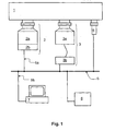
- a recipient 1 is shown, are connected to the flanges via vacuum devices.
- the recipient may be a simple vacuum chamber, a multi-chamber system, or part of a complex vacuum system, where the vacuum devices may be located at different points in the system.
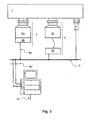
- a first vacuum pump 2 a second vacuum pump 3 and a measuring device 4 are shown in FIGS. 1 to 3.
- the vacuum pump 2 has a pump part 2a with the pump system for generating a vacuum and an operating device 2b.
- This operating device 2b includes the control electronics for driving the electrical and electronic components of the pump part 2a, in particular of the drive motor. In the operating device 2b and power unit power supply can be arranged.
- the vacuum device 3 is a vacuum pump in which the pump part 3a with a pumping system and operating device 3b are separate from each other and communicate with each other via one or more cables.
- the vacuum device 4 is designed as a measuring device, for example a pressure gauge, wherein it contains at least one electronic unit from which measured values are forwarded to connectable devices.
- a control unit 6 is used in a known manner for controlling the vacuum devices. Here, for example, from a central point, the switching on and off of individual vacuum devices can be done depending on the running in the vacuum system process.
- a bus system 5 is provided, to which control unit and vacuum devices are connected, for example via a cable connection 5a.
- the connected devices and units are assigned addresses at which they can be reached for communication. Cables and radio links can be used as means of communication for designing the bus system.
- conventional protocols and methods can be used, for example Internet protocols or those that are used in the field of industry-standard "programmable logic controller (PLC)".
- a management unit 7 is connected to the bus system 5 via a cable connection 5b.
- This administrative unit collects and distributes configuration data of the vacuum devices.
- the bus system is designed in this example so that a parallel communication can be performed.
- the bus system must be designed in such a way that it permits quasi-simultaneous operation with several so-called masters. Examples of such bus systems are Ethernet and the "Process Field Bus” (Profibus). Management and control unit are masters in this context.
- the administrative unit 7 has a radio module and communicates via a radio link 5b 'with a radio module connected to a second bus system 5'.
- the second bus system is arranged parallel to the first bus system 5, so that a data exchange can take place via both.
- the radio link 5b 'a as a connection to the bus system, it is particularly easy to implement a temporarily connectable administration unit. It may then take the form of, for example, a personal digital assistant (PDA) or a portable computer (“laptop”) equipped with a radio module. It is also conceivable to build the complete bus system 5 'or parts thereof via radio links.
- PDA personal digital assistant
- laptop portable computer
- control unit and the administrative unit are parts of a control unit 9, which is connected to the bus system 5 via a connection 5b.
- this connection can consist of several cables. which is given by suitable means the data of both units 6 and 7. It is possible for a management unit to receive and send data via an outside connection 10.
- Such a connection may be, for example, a computer network connection such as intranet or internet.
- the data exchanges between vacuum device and control unit on the one hand and vacuum unit and management unit according to the invention on the other hand are independent of each other.
- the administrative unit can read out data from the vacuum device without substantially impairing the data exchange between the vacuum device and the control unit.
- the data transferred in the data exchange consists of control data, operating data and configuration data.
- the control data in particular include setting commands and instructions that are transmitted from the control unit to the vacuum device and, for example, trigger actions such as reading a measured value, changing the rotational speed, and the like.
- the operating data comprise the actual values of the vacuum device and are only read out by the control and / or management unit.
- the configuration data includes such data as pump type, software status, settings of parameters such as number of cycles and duration of measurement recordings, temperature of temperature management systems, coolant flow, and the like.
- the sum of all configuration data of a vacuum device forms a configuration data record, the configuration data describe the configuration of the vacuum device.
- the control unit sends data to single or multiple vacuum devices via the bus system. These data are received by the operating devices on the vacuum devices, interpreted as commands and the associated actions are triggered. For example, if the vacuum device is a vacuum pump, such an action may be to accelerate from a standby state to a reduced one Rotor speed to be at final speed. Since the running of the process in the recipient causes certain actions and conditions of the vacuum devices, the operating devices of the vacuum devices send operating data to the control unit describing their condition. This transmission may occur at regular, predefined intervals or in response to a corresponding control unit command. Sending the data between the operating devices and the control unit represents a data exchange.
- the management unit transmits and receives data, wherein this data exchange with the vacuum devices takes place and does not hinder the data exchange described above.
- These data are configuration data or operational data or both together.
- These data can be used in many ways, for example, they can be displayed on a display device, stored in a data memory or transmitted over a computer network.
- An example of the application of the method is that a vacuum pump contains a temperature sensor whose temperature signal is sent as part of the operating data to the management unit. This stores each temperature value or only a predetermined proportion of the temperature values and simultaneously displays on a display device, such as a screen. It is also possible for the administrative unit to display all or part of the current operating and configuration data of the arrangement, thus representing and visualizing its state.
- the management unit sends a command to the vacuum device to which it in turn transmits its configuration data.
- These are stored in a step B of the method in the administrative unit, stating the address of the vacuum device within the bus system, whereby an assignment of the configuration data takes place to the vacuum device stored. Subsequently, the vacuum device is replaced and built a similar type of vacuum device in its place in the assembly. Again, the management unit sends a command to the address of the vacuum device and receives response data transmitted. The administrative unit now compares all or part of the configuration data record.
- the configuration data stored in the memory of the administrative unit is completely or partially transferred to the vacuum device, so that it can subsequently fulfill the function of the old vacuum device.
- the step A of transmitting configuration data or operation data or both together from a vacuum device to the management unit may be event-driven or cyclic. Cyclic means that the step is repeated after a predetermined time interval has expired. This time interval is stored in the administrative unit or in the vacuum device. It can be fixed or changeable. An example of event control is when a user operates the administrative unit and thereby initiates the data exchange.
Landscapes
- Engineering & Computer Science (AREA)
- Physics & Mathematics (AREA)
- General Physics & Mathematics (AREA)
- Mechanical Engineering (AREA)
- General Engineering & Computer Science (AREA)
- Computer Networks & Wireless Communication (AREA)
- Compressors, Vaccum Pumps And Other Relevant Systems (AREA)
- Control Of Positive-Displacement Pumps (AREA)
- Hardware Redundancy (AREA)
Applications Claiming Priority (1)
| Application Number | Priority Date | Filing Date | Title |
|---|---|---|---|
| DE102006045022.1A DE102006045022B4 (de) | 2006-09-23 | 2006-09-23 | Anordnung mit Vakuumgerät und Verfahren zu derem Betrieb |
Publications (3)
| Publication Number | Publication Date |
|---|---|
| EP1903530A2 true EP1903530A2 (fr) | 2008-03-26 |
| EP1903530A3 EP1903530A3 (fr) | 2014-09-17 |
| EP1903530B1 EP1903530B1 (fr) | 2020-07-22 |
Family
ID=38969547
Family Applications (1)
| Application Number | Title | Priority Date | Filing Date |
|---|---|---|---|
| EP07017431.3A Active EP1903530B1 (fr) | 2006-09-23 | 2007-09-06 | Agencement doté d'un appareil sous vide et son procédé de fonctionnement |
Country Status (2)
| Country | Link |
|---|---|
| EP (1) | EP1903530B1 (fr) |
| DE (1) | DE102006045022B4 (fr) |
Cited By (5)
| Publication number | Priority date | Publication date | Assignee | Title |
|---|---|---|---|---|
| EP2827314A1 (fr) * | 2013-06-20 | 2015-01-21 | Pfeiffer Vacuum GmbH | Agencement sous vide doté d'un appareil sous vide et procédé de détection de données communiquées dans une ligne de communication entre un appareil sous vide et un dispositif central de commande |
| EP3620663A1 (fr) * | 2018-09-06 | 2020-03-11 | Pfeiffer Vacuum Gmbh | Dispositif à vide |
| EP3620661A1 (fr) * | 2019-08-30 | 2020-03-11 | Pfeiffer Vacuum Gmbh | Dispositif de raccordement, système et procédé de fonctionnement d'un dispositif de raccordement |
| EP3626973A1 (fr) * | 2019-08-12 | 2020-03-25 | Pfeiffer Vacuum Gmbh | Système à vide et procédé d'identification de modules électroniques dans un tel système à vide |
| EP3951738A3 (fr) * | 2021-12-13 | 2022-07-06 | Pfeiffer Vacuum Technology AG | Dispositif et procédé de communication doté d'un appareil sous vide |
Families Citing this family (1)
| Publication number | Priority date | Publication date | Assignee | Title |
|---|---|---|---|---|
| DE102024132173B3 (de) * | 2024-11-05 | 2026-02-12 | Endress+Hauser Flowtec Ag | Messdatenverarbeitungssystem und Prozessanlage |
Family Cites Families (7)
| Publication number | Priority date | Publication date | Assignee | Title |
|---|---|---|---|---|
| CA2203561C (fr) * | 1994-10-24 | 2004-09-21 | Thomas Andrew Boyd | Appareil permettant d'acceder a des equipements du domaine d'exploitation a l'interieur d'un systeme de commande distribue |
| US5793963A (en) * | 1994-10-24 | 1998-08-11 | Fisher Rosemount Systems, Inc. | Apparatus for providing non-redundant secondary access to field devices in a distributed control system |
| US5971711A (en) * | 1996-05-21 | 1999-10-26 | Ebara Corporation | Vacuum pump control system |
| US6272400B1 (en) * | 1998-07-13 | 2001-08-07 | Helix Technology Corporation | Vacuum network controller |
| DE10114127A1 (de) * | 2001-03-22 | 2002-09-26 | Abb Patent Gmbh | Verfahren zur Kommunikation mit einem Feldgerät |
| US7016751B2 (en) * | 2001-07-13 | 2006-03-21 | Helix Technology Corporation | Vacuum system central control information server |
| DE102004036046A1 (de) | 2004-07-24 | 2006-02-16 | Robert Bosch Gmbh | System und Verfahren zur Steuerung oder Regelung der Betriebsabläufe bei einem Fahrzeug |
-
2006
- 2006-09-23 DE DE102006045022.1A patent/DE102006045022B4/de active Active
-
2007
- 2007-09-06 EP EP07017431.3A patent/EP1903530B1/fr active Active
Cited By (5)
| Publication number | Priority date | Publication date | Assignee | Title |
|---|---|---|---|---|
| EP2827314A1 (fr) * | 2013-06-20 | 2015-01-21 | Pfeiffer Vacuum GmbH | Agencement sous vide doté d'un appareil sous vide et procédé de détection de données communiquées dans une ligne de communication entre un appareil sous vide et un dispositif central de commande |
| EP3620663A1 (fr) * | 2018-09-06 | 2020-03-11 | Pfeiffer Vacuum Gmbh | Dispositif à vide |
| EP3626973A1 (fr) * | 2019-08-12 | 2020-03-25 | Pfeiffer Vacuum Gmbh | Système à vide et procédé d'identification de modules électroniques dans un tel système à vide |
| EP3620661A1 (fr) * | 2019-08-30 | 2020-03-11 | Pfeiffer Vacuum Gmbh | Dispositif de raccordement, système et procédé de fonctionnement d'un dispositif de raccordement |
| EP3951738A3 (fr) * | 2021-12-13 | 2022-07-06 | Pfeiffer Vacuum Technology AG | Dispositif et procédé de communication doté d'un appareil sous vide |
Also Published As
| Publication number | Publication date |
|---|---|
| DE102006045022B4 (de) | 2026-04-23 |
| EP1903530A3 (fr) | 2014-09-17 |
| DE102006045022A1 (de) | 2008-03-27 |
| EP1903530B1 (fr) | 2020-07-22 |
Similar Documents
| Publication | Publication Date | Title |
|---|---|---|
| EP4004664B1 (fr) | Procédé pour vérifier l'inventaire des appareils de terrain enregistrés dans un système de gestion des actifs | |
| EP0923038B1 (fr) | Dispositif de mesure pour la détermination de propriétés physiques et/ou chimiques de gaz, de liquides et/ou de solides | |
| DE102010029952B4 (de) | Verfahren zum Integrieren von zumindest einem Feldgerät in ein Netzwerk der Automatisierungstechnik | |
| EP1088259B1 (fr) | Commande electronique pour des installations de production d'air comprime ou de vide | |
| EP2659317B1 (fr) | Appareil de terrain avec compatibilité à long terme du micrologiciel | |
| EP1779203B1 (fr) | Identification de parametres d'appareils de terrain dans la technique d'automatisation | |
| DE102007026678A1 (de) | Verfahren zum Austausch eines defekten Feldgerätes gegen ein neues Feldgerät in einem über digitalen Feldbus kommunizierenden System, insbesondere Automatisierungssystem | |
| DE10159697A1 (de) | Redundante Einrichtungen in einem Prozesssteuersystem | |
| EP1903530B1 (fr) | Agencement doté d'un appareil sous vide et son procédé de fonctionnement | |
| DE102012105446B4 (de) | Vorrichtung zur Bestimmung und/oder Überwachung einer chemischen oder physikalischen Prozessgröße in der Automatisierungstechnik | |
| WO2009074544A1 (fr) | Procédé pour faire fonctionner un système présentant un appareil de terrain et un système de commande | |
| EP3384352B1 (fr) | Procédé et système d'optimisation de la mise en service d'au moins un appareil de champ d'une pluralité d'appareils de champ de la technique d'automatisation | |
| DE102007029321B4 (de) | Verfahren zum Betreiben eines Feldgerätes in einem benutzerfreundlichen Modus | |
| EP3637205A1 (fr) | Déclenchement de l'image sur une station client de l'opérateur | |
| EP4036543A1 (fr) | Capteur de pression | |
| EP3384353B1 (fr) | Procédé et système d'optimisation de la commande d'au moins un appareil de champ d'une pluralité d'appareils de champ du secteur de la robotique | |
| EP1941331B1 (fr) | Dispositif d exploitation d une installation de processus | |
| WO2006018345A1 (fr) | Procede pour faire fonctionner un appareil de champ d'automatisation | |
| WO2006092382A2 (fr) | Systeme d'ingenierie | |
| WO2019011603A1 (fr) | Procédé et unité de conversion de données pour surveiller une installation de la technologie d'automatisation | |
| DE10157539A1 (de) | Engineeringsystem und Automatisierungssystem | |
| EP1431898A2 (fr) | Système d'automatisation et méthode pour la mise en oeuvre d'un tel système | |
| EP3970345B1 (fr) | Sortie sans configuration de données utiles contenues dans des télégrammes ethernet | |
| EP2687930B1 (fr) | Unité d'automatisation destinée à la commande d'un appareil ou d'une installation | |
| DE102006004633A1 (de) | Verteiltes Automatisierungssystem |
Legal Events
| Date | Code | Title | Description |
|---|---|---|---|
| PUAI | Public reference made under article 153(3) epc to a published international application that has entered the european phase |
Free format text: ORIGINAL CODE: 0009012 |
|
| AK | Designated contracting states |
Kind code of ref document: A2 Designated state(s): AT BE BG CH CY CZ DE DK EE ES FI FR GB GR HU IE IS IT LI LT LU LV MC MT NL PL PT RO SE SI SK TR |
|
| AX | Request for extension of the european patent |
Extension state: AL BA HR MK YU |
|
| PUAL | Search report despatched |
Free format text: ORIGINAL CODE: 0009013 |
|
| AK | Designated contracting states |
Kind code of ref document: A3 Designated state(s): AT BE BG CH CY CZ DE DK EE ES FI FR GB GR HU IE IS IT LI LT LU LV MC MT NL PL PT RO SE SI SK TR |
|
| AX | Request for extension of the european patent |
Extension state: AL BA HR MK RS |
|
| RIC1 | Information provided on ipc code assigned before grant |
Ipc: G08C 19/00 20060101AFI20140812BHEP Ipc: G08C 17/02 20060101ALI20140812BHEP |
|
| 17P | Request for examination filed |
Effective date: 20150317 |
|
| RBV | Designated contracting states (corrected) |
Designated state(s): AT BE BG CH CY CZ DE DK EE ES FI FR GB GR HU IE IS IT LI LT LU LV MC MT NL PL PT RO SE SI SK TR |
|
| AKX | Designation fees paid |
Designated state(s): AT BE BG CH CY CZ DE DK EE ES FI FR GB GR HU IE IS IT LI LT LU LV MC MT NL PL PT RO SE SI SK TR |
|
| AXX | Extension fees paid |
Extension state: MK Extension state: BA Extension state: HR Extension state: AL Extension state: RS |
|
| STAA | Information on the status of an ep patent application or granted ep patent |
Free format text: STATUS: EXAMINATION IS IN PROGRESS |
|
| 17Q | First examination report despatched |
Effective date: 20180411 |
|
| GRAP | Despatch of communication of intention to grant a patent |
Free format text: ORIGINAL CODE: EPIDOSNIGR1 |
|
| STAA | Information on the status of an ep patent application or granted ep patent |
Free format text: STATUS: GRANT OF PATENT IS INTENDED |
|
| INTG | Intention to grant announced |
Effective date: 20200330 |
|
| GRAS | Grant fee paid |
Free format text: ORIGINAL CODE: EPIDOSNIGR3 |
|
| GRAA | (expected) grant |
Free format text: ORIGINAL CODE: 0009210 |
|
| STAA | Information on the status of an ep patent application or granted ep patent |
Free format text: STATUS: THE PATENT HAS BEEN GRANTED |
|
| AK | Designated contracting states |
Kind code of ref document: B1 Designated state(s): AT BE BG CH CY CZ DE DK EE ES FI FR GB GR HU IE IS IT LI LT LU LV MC MT NL PL PT RO SE SI SK TR |
|
| REG | Reference to a national code |
Ref country code: GB Ref legal event code: FG4D Free format text: NOT ENGLISH |
|
| REG | Reference to a national code |
Ref country code: CH Ref legal event code: EP |
|
| REG | Reference to a national code |
Ref country code: DE Ref legal event code: R096 Ref document number: 502007016901 Country of ref document: DE |
|
| REG | Reference to a national code |
Ref country code: AT Ref legal event code: REF Ref document number: 1294148 Country of ref document: AT Kind code of ref document: T Effective date: 20200815 |
|
| REG | Reference to a national code |
Ref country code: IE Ref legal event code: FG4D Free format text: LANGUAGE OF EP DOCUMENT: GERMAN |
|
| REG | Reference to a national code |
Ref country code: LT Ref legal event code: MG4D |
|
| PG25 | Lapsed in a contracting state [announced via postgrant information from national office to epo] |
Ref country code: LT Free format text: LAPSE BECAUSE OF FAILURE TO SUBMIT A TRANSLATION OF THE DESCRIPTION OR TO PAY THE FEE WITHIN THE PRESCRIBED TIME-LIMIT Effective date: 20200722 Ref country code: PT Free format text: LAPSE BECAUSE OF FAILURE TO SUBMIT A TRANSLATION OF THE DESCRIPTION OR TO PAY THE FEE WITHIN THE PRESCRIBED TIME-LIMIT Effective date: 20201123 Ref country code: SE Free format text: LAPSE BECAUSE OF FAILURE TO SUBMIT A TRANSLATION OF THE DESCRIPTION OR TO PAY THE FEE WITHIN THE PRESCRIBED TIME-LIMIT Effective date: 20200722 Ref country code: BG Free format text: LAPSE BECAUSE OF FAILURE TO SUBMIT A TRANSLATION OF THE DESCRIPTION OR TO PAY THE FEE WITHIN THE PRESCRIBED TIME-LIMIT Effective date: 20201022 Ref country code: ES Free format text: LAPSE BECAUSE OF FAILURE TO SUBMIT A TRANSLATION OF THE DESCRIPTION OR TO PAY THE FEE WITHIN THE PRESCRIBED TIME-LIMIT Effective date: 20200722 Ref country code: GR Free format text: LAPSE BECAUSE OF FAILURE TO SUBMIT A TRANSLATION OF THE DESCRIPTION OR TO PAY THE FEE WITHIN THE PRESCRIBED TIME-LIMIT Effective date: 20201023 Ref country code: FI Free format text: LAPSE BECAUSE OF FAILURE TO SUBMIT A TRANSLATION OF THE DESCRIPTION OR TO PAY THE FEE WITHIN THE PRESCRIBED TIME-LIMIT Effective date: 20200722 |
|
| PG25 | Lapsed in a contracting state [announced via postgrant information from national office to epo] |
Ref country code: LV Free format text: LAPSE BECAUSE OF FAILURE TO SUBMIT A TRANSLATION OF THE DESCRIPTION OR TO PAY THE FEE WITHIN THE PRESCRIBED TIME-LIMIT Effective date: 20200722 Ref country code: PL Free format text: LAPSE BECAUSE OF FAILURE TO SUBMIT A TRANSLATION OF THE DESCRIPTION OR TO PAY THE FEE WITHIN THE PRESCRIBED TIME-LIMIT Effective date: 20200722 Ref country code: IS Free format text: LAPSE BECAUSE OF FAILURE TO SUBMIT A TRANSLATION OF THE DESCRIPTION OR TO PAY THE FEE WITHIN THE PRESCRIBED TIME-LIMIT Effective date: 20201122 |
|
| PG25 | Lapsed in a contracting state [announced via postgrant information from national office to epo] |
Ref country code: NL Free format text: LAPSE BECAUSE OF FAILURE TO SUBMIT A TRANSLATION OF THE DESCRIPTION OR TO PAY THE FEE WITHIN THE PRESCRIBED TIME-LIMIT Effective date: 20200722 |
|
| REG | Reference to a national code |
Ref country code: DE Ref legal event code: R097 Ref document number: 502007016901 Country of ref document: DE |
|
| PG25 | Lapsed in a contracting state [announced via postgrant information from national office to epo] |
Ref country code: RO Free format text: LAPSE BECAUSE OF FAILURE TO SUBMIT A TRANSLATION OF THE DESCRIPTION OR TO PAY THE FEE WITHIN THE PRESCRIBED TIME-LIMIT Effective date: 20200722 Ref country code: MC Free format text: LAPSE BECAUSE OF FAILURE TO SUBMIT A TRANSLATION OF THE DESCRIPTION OR TO PAY THE FEE WITHIN THE PRESCRIBED TIME-LIMIT Effective date: 20200722 Ref country code: EE Free format text: LAPSE BECAUSE OF FAILURE TO SUBMIT A TRANSLATION OF THE DESCRIPTION OR TO PAY THE FEE WITHIN THE PRESCRIBED TIME-LIMIT Effective date: 20200722 Ref country code: DK Free format text: LAPSE BECAUSE OF FAILURE TO SUBMIT A TRANSLATION OF THE DESCRIPTION OR TO PAY THE FEE WITHIN THE PRESCRIBED TIME-LIMIT Effective date: 20200722 |
|
| REG | Reference to a national code |
Ref country code: CH Ref legal event code: PL |
|
| PLBE | No opposition filed within time limit |
Free format text: ORIGINAL CODE: 0009261 |
|
| STAA | Information on the status of an ep patent application or granted ep patent |
Free format text: STATUS: NO OPPOSITION FILED WITHIN TIME LIMIT |
|
| REG | Reference to a national code |
Ref country code: BE Ref legal event code: MM Effective date: 20200930 |
|
| 26N | No opposition filed |
Effective date: 20210423 |
|
| PG25 | Lapsed in a contracting state [announced via postgrant information from national office to epo] |
Ref country code: SK Free format text: LAPSE BECAUSE OF FAILURE TO SUBMIT A TRANSLATION OF THE DESCRIPTION OR TO PAY THE FEE WITHIN THE PRESCRIBED TIME-LIMIT Effective date: 20200722 Ref country code: LU Free format text: LAPSE BECAUSE OF NON-PAYMENT OF DUE FEES Effective date: 20200906 |
|
| PG25 | Lapsed in a contracting state [announced via postgrant information from national office to epo] |
Ref country code: FR Free format text: LAPSE BECAUSE OF NON-PAYMENT OF DUE FEES Effective date: 20200922 |
|
| PG25 | Lapsed in a contracting state [announced via postgrant information from national office to epo] |
Ref country code: SI Free format text: LAPSE BECAUSE OF FAILURE TO SUBMIT A TRANSLATION OF THE DESCRIPTION OR TO PAY THE FEE WITHIN THE PRESCRIBED TIME-LIMIT Effective date: 20200722 Ref country code: LI Free format text: LAPSE BECAUSE OF NON-PAYMENT OF DUE FEES Effective date: 20200930 Ref country code: IE Free format text: LAPSE BECAUSE OF NON-PAYMENT OF DUE FEES Effective date: 20200906 Ref country code: CH Free format text: LAPSE BECAUSE OF NON-PAYMENT OF DUE FEES Effective date: 20200930 Ref country code: BE Free format text: LAPSE BECAUSE OF NON-PAYMENT OF DUE FEES Effective date: 20200930 |
|
| REG | Reference to a national code |
Ref country code: NL Ref legal event code: MP Effective date: 20200722 |
|
| REG | Reference to a national code |
Ref country code: AT Ref legal event code: MM01 Ref document number: 1294148 Country of ref document: AT Kind code of ref document: T Effective date: 20200906 |
|
| PG25 | Lapsed in a contracting state [announced via postgrant information from national office to epo] |
Ref country code: AT Free format text: LAPSE BECAUSE OF NON-PAYMENT OF DUE FEES Effective date: 20200906 |
|
| PG25 | Lapsed in a contracting state [announced via postgrant information from national office to epo] |
Ref country code: TR Free format text: LAPSE BECAUSE OF FAILURE TO SUBMIT A TRANSLATION OF THE DESCRIPTION OR TO PAY THE FEE WITHIN THE PRESCRIBED TIME-LIMIT Effective date: 20200722 Ref country code: MT Free format text: LAPSE BECAUSE OF FAILURE TO SUBMIT A TRANSLATION OF THE DESCRIPTION OR TO PAY THE FEE WITHIN THE PRESCRIBED TIME-LIMIT Effective date: 20200722 Ref country code: CY Free format text: LAPSE BECAUSE OF FAILURE TO SUBMIT A TRANSLATION OF THE DESCRIPTION OR TO PAY THE FEE WITHIN THE PRESCRIBED TIME-LIMIT Effective date: 20200722 |
|
| PGFP | Annual fee paid to national office [announced via postgrant information from national office to epo] |
Ref country code: IT Payment date: 20250923 Year of fee payment: 19 |
|
| PGFP | Annual fee paid to national office [announced via postgrant information from national office to epo] |
Ref country code: GB Payment date: 20250918 Year of fee payment: 19 |
|
| PGFP | Annual fee paid to national office [announced via postgrant information from national office to epo] |
Ref country code: CZ Payment date: 20250828 Year of fee payment: 19 |
|
| PGFP | Annual fee paid to national office [announced via postgrant information from national office to epo] |
Ref country code: DE Payment date: 20251126 Year of fee payment: 19 |