EP3620661A1 - Dispositif de raccordement, système et procédé de fonctionnement d'un dispositif de raccordement - Google Patents
Dispositif de raccordement, système et procédé de fonctionnement d'un dispositif de raccordement Download PDFInfo
- Publication number
- EP3620661A1 EP3620661A1 EP19194579.9A EP19194579A EP3620661A1 EP 3620661 A1 EP3620661 A1 EP 3620661A1 EP 19194579 A EP19194579 A EP 19194579A EP 3620661 A1 EP3620661 A1 EP 3620661A1
- Authority
- EP
- European Patent Office
- Prior art keywords
- operating
- message
- connection
- vacuum
- vacuum device
- Prior art date
- Legal status (The legal status is an assumption and is not a legal conclusion. Google has not performed a legal analysis and makes no representation as to the accuracy of the status listed.)
- Granted
Links
Images


Classifications
-
- F—MECHANICAL ENGINEERING; LIGHTING; HEATING; WEAPONS; BLASTING
- F04—POSITIVE - DISPLACEMENT MACHINES FOR LIQUIDS; PUMPS FOR LIQUIDS OR ELASTIC FLUIDS
- F04D—NON-POSITIVE-DISPLACEMENT PUMPS
- F04D27/00—Control, e.g. regulation, of pumps, pumping installations or pumping systems specially adapted for elastic fluids
- F04D27/001—Testing thereof; Determination or simulation of flow characteristics; Stall or surge detection, e.g. condition monitoring
-
- F—MECHANICAL ENGINEERING; LIGHTING; HEATING; WEAPONS; BLASTING
- F04—POSITIVE - DISPLACEMENT MACHINES FOR LIQUIDS; PUMPS FOR LIQUIDS OR ELASTIC FLUIDS
- F04D—NON-POSITIVE-DISPLACEMENT PUMPS
- F04D19/00—Axial-flow pumps
- F04D19/02—Multi-stage pumps
- F04D19/04—Multi-stage pumps specially adapted to the production of a high vacuum, e.g. molecular pumps
-
- F—MECHANICAL ENGINEERING; LIGHTING; HEATING; WEAPONS; BLASTING
- F04—POSITIVE - DISPLACEMENT MACHINES FOR LIQUIDS; PUMPS FOR LIQUIDS OR ELASTIC FLUIDS
- F04D—NON-POSITIVE-DISPLACEMENT PUMPS
- F04D25/00—Pumping installations or systems
- F04D25/02—Units comprising pumps and their driving means
- F04D25/06—Units comprising pumps and their driving means the pump being electrically driven
-
- G—PHYSICS
- G08—SIGNALLING
- G08C—TRANSMISSION SYSTEMS FOR MEASURED VALUES, CONTROL OR SIMILAR SIGNALS
- G08C19/00—Electric signal transmission systems
-
- G—PHYSICS
- G08—SIGNALLING
- G08C—TRANSMISSION SYSTEMS FOR MEASURED VALUES, CONTROL OR SIMILAR SIGNALS
- G08C2201/00—Transmission systems of control signals via wireless link
- G08C2201/50—Receiving or transmitting feedback, e.g. replies, status updates, acknowledgements, from the controlled devices
- G08C2201/51—Remote controlling of devices based on replies, status thereof
Definitions
- the present invention relates to a connection device having a first connection for a vacuum device and a plurality of second connections, each for an operating device for the vacuum device.
- the invention also relates to a system having a connection device with a first connection and a plurality of second connections, a vacuum device being connected to the first connection and a respective operating device for the vacuum device being connected to the plurality of second connections.
- the invention also relates to a method for operating a connection device with a first connection and a plurality of second connections.
- Different vacuum components can only contain one communication connection (which can also be referred to simply as a connection), for example in the form of an RS-485 interface with a specified protocol, which is used for connection to operating devices, for example a DCU (" Display Control Unit “; German: display control unit) or HPU (" Handheld programming unit “; German: portable programming unit).
- Suitable components for example a USB / RS-485 converter
- PC personal computer
- One or more devices e.g. several TMPs
- a problem here is that when using a master (in other words: an operating device or an operating device) that initiates the communication, the connection of a second master or a second operating device is not possible.
- a master in other words: an operating device or an operating device
- the connection of a second master or a second operating device is not possible.
- this can be desirable if, for example, a pumping station is to be connected to a PC.
- the RS-485 connection to the DCU must be interrupted and the pumping station must be connected to the PC instead.
- the display of the DCU can then not be used.
- connection device with the features of claim 1, and in particular in that the connection device has: a first connection for a vacuum device, in particular one Vacuum pump or an accessory unit for a vacuum pump or a system consisting of one or more vacuum pumps and / or one or more accessory units, for example a pumping station; a plurality of second connections, each for an operating device for the vacuum device; and a communication control unit configured to: receive a first operating message from a first operating device; Forwarding the first operating message to the vacuum device; Receiving a second operating message from a second operating device after the first operating message has been received; Receiving a response to the first operator message from the vacuum device; and forwarding the second operating message to the vacuum device after the response has been received.
- a first connection for a vacuum device in particular one Vacuum pump or an accessory unit for a vacuum pump or a system consisting of one or more vacuum pumps and / or one or more accessory units, for example a pumping station
- a plurality of second connections each for an operating device for the vacuum device
- a vacuum device and a plurality of operating devices can be connected to a connecting device, and the connecting device can forward messages (which can be referred to as operating messages) from each of the operating devices to the vacuum device.
- the connecting device can forward messages (which can be referred to as operating messages) from each of the operating devices to the vacuum device.
- a further message to be forwarded is only forwarded to the vacuum device when a response to the previously transmitted message has been received by the vacuum device.
- connection device With such a connection device, more than one operating device for the vacuum device can be connected to the vacuum device. It will be understood that even if only two operating devices are described in different exemplary embodiments for the sake of simpler description, more than two operating devices can also be connected to the connecting device; for this purpose, the connection device can accordingly contain more than two second connections.
- Each of the connected multiple operating devices can then access the vacuum device (ie the control of the vacuum device) as usual, that is For example, sending control commands, receiving responses to control commands, querying parameters or querying operating states.
- An operating device can be any device suitable for communication with the vacuum device.
- the operating device can be used to control the vacuum device, to set parameters for operating the vacuum device, to read parameters of the vacuum device, to query the operating state of the vacuum device or any other type of read or write access to the vacuum device (in particular to a control device of the vacuum device ) be set up.
- the operating device can also contain or be a display device.
- the operating message can contain any type of data that is sent from an operating device to the vacuum device.
- an operating message can contain control commands or commands for querying or setting parameters or operating states of the vacuum device.
- the operating message does not have to contain any addressing information for the vacuum device, since by default each operating device is provided for the operation of exactly one vacuum device.
- the response to the operating message can include confirmation of receipt of the operating message, confirmation of the execution of commands contained in the operating message, or more complex response information (such as the value of queried parameters or operating states).
- a connection can, for example, be male or female and / or comprise a plug or a socket, other types of connection also being conceivable.
- connection device is not noticeable or transparent for the vacuum device, i. that is, the vacuum device need not be set up specifically for operation with the connection device, but the connection device is simply connected between the vacuum device and the several operating devices.
- the operation is not noticeable or transparent for the connected operating devices either.
- the operating devices do not have to be set up specifically for operation with the connection device, but can, as usual, output operating messages and receive responses to the operating messages.
- the request for an operating device can be completely completed according to the invention before the next request (for example another operating device) is processed.
- the next request for example another operating device
- a response to a first operating message is received. It is therefore impossible that an undefined state arises in the vacuum device due to the simultaneous (or almost simultaneous) arrival of operating messages, which could lead to errors in the operation of the vacuum device.
- the communication control unit is further configured to forward the response to the first operating device.
- the response can be forwarded to the first operating devices independently of the forwarding of the second operating message to the vacuum device.
- the response can be forwarded to the first operating devices before, after or during the forwarding of the second operating message to the vacuum device.
- the communication control unit is also set up to detect collisions when receiving operator messages of more than an operating device. For example, if the first control message and the second control message arrive at the connection device at the same time (or arrive at the connection device almost simultaneously, for example if the second control message arrives at the connection device even before the first control message has been forwarded to the vacuum device), the connection device can recognize that there is a collision and can then forward the two or more operating messages to the vacuum device in succession.
- the communication control unit is further configured to prioritize the operator messages into a priority operator message and a secondary operator message when receiving operator messages from more than one operator control device.
- the prioritization can take place using predefined rules.
- the prioritization can be based on which of the second connections the operator messages are received (or received). This makes it possible, for example, to define an operating device as a priority (this operating device is then connected to a predetermined second connection of the connecting device).
- the prioritization can be based on the content of the operator messages. This makes it possible, for example, to forward urgent operating messages to the vacuum device in a preferred manner (in other words: priority).
- the prioritization can be based on the history of operator messages that have already been forwarded. It is thus possible, for example, to ensure that no operating device has to wait too long for an operating message issued by it to be forwarded.
- the prioritization can be based on the size of the operator message to be forwarded. This makes it possible, for example, to keep the effort of temporarily storing subordinate operator messages as low as possible, for example by large operator messages are primarily forwarded.
- the prioritization can be based on the duration of the expected execution of the operating message by the vacuum device. This makes it possible, for example, to give priority to operating messages that are likely to be processed quickly on the vacuum device and thus to keep the waiting time of operating messages that have not yet been forwarded as short as possible.
- the communication control unit can also be set up to: forward the priority operating message to the vacuum device; and storing the subordinate operator message.
- the communication control unit or another component of the connection device can have a memory in which the subordinate operating message can be stored.
- a further (for example third) operating message is received, it can be determined (for example on the predefined rules for prioritization described above) whether after receiving the response to the first operating message is the (stored) second operating message, which was previously classified as subordinate, or the third operating message is to be forwarded to the vacuum device.
- the communication control unit can also be set up to preprocess a received operating message before further processing, in particular before forwarding. Preprocessing can include changing or completely deleting a received operating message, so that either a modified operating message is forwarded to the vacuum device or the operating message is rejected without being forwarded to the vacuum device.
- the communication control unit can also be set up to forward operating messages with read-only access to the vacuum device and to discard operating messages with non-read-only access to the vacuum device if the operating message is received by an operating device via a predetermined second connection.
- a predetermined operating device that is to say the operating device which is connected to the connecting device via the predetermined second connection
- the predetermined operating device can only be allowed to query the status of the vacuum device or to query parameters of the vacuum device, whereas the predetermined operating device cannot be allowed to send control commands or commands for changing parameters to the vacuum device. If the operating message is rejected, the connection device can issue a corresponding notification of the rejection to the predetermined operating device.
- the communication control unit can also be set up to forward operating messages with only access to predetermined parameters of the vacuum device and to discard operating messages with access going beyond the predetermined parameters of the vacuum device if the operating message is received by an operating device via a predetermined second connection.
- This can be used, for example, to prevent an unauthorized (ie connected to the specified second connection) operating device from changing critical parameters or querying confidential parameters. If the operating message is rejected, the connection device can use a corresponding one Output discard notification to unauthorized operator.
- the communication control unit can also be set up to reject an operating message received from an operating device via a predetermined second connection without forwarding the operating message.
- the control device can thus be completely excluded from the operation of the vacuum device. Nevertheless, the operating device can receive status messages from the vacuum device, for example.
- the communication control unit can also be set up to create a response to an operating message without forwarding the operating message. If, for example, the connection device can already determine (for example by means of previously received answers or information stored internally in the connection device) which answer the vacuum device would give to the operating message, and if the operating message has no influence on the operation of the vacuum device (if so, for example no control information or parameters to be set are contained in the operating message), the connection device can relieve the vacuum device in that it generates the response instead of the vacuum device and transmits it to the operating device.
- the first port and the plurality of second ports may have serial ports.
- the serial connections can be set up according to RS-232 (or ANSI EIA /) TIA-232-F or EIA-232), RS-422 (or EIA-422 or ITU-T V.11), RS-423 ( or EIA-423) or RS-485 (or EIA-485), LVDS (Low Voltage Differential Signaling) or TTY.
- the connection device can be a device separate from the vacuum device and the operating devices (for example arranged in a separate housing and via connections to the vacuum device and connected to the operating devices) or integrated into the vacuum device or into one of the operating devices.
- the object is also achieved by a system with the features of the claim directed to it, in particular in that the system has a connection device as described above with a vacuum device connected to the first connection and a plurality of operating devices for the vacuum device connected to a respective second connection .
- the object is also achieved by a method containing the features of the independent method claim for operating a connection device having a first connection for a vacuum device, in particular a vacuum pump or an accessory unit for a vacuum pump, and a plurality of second connections for each operating device for the vacuum device, in particular in that the method has at least the following steps: receiving a first operating message from a first operating device; Forwarding the first operating message to the vacuum device; Receiving a second operating message from a second operating device after the first operating message has been received; Receiving a response to the first operator message from the vacuum device; and forwarding the second operating message to the vacuum device after the response has been received.
- connection device for example a multiplexer for serial communication in vacuum devices
- the sole serial connection for example an RS-485 interface with a specified protocol, in particular PV (Pfeiffer Vaccuum) protocol
- PV Peripheral Component Interconnect
- the connection device for example with an RS-485 connection to the device (slave) and two or more RS-485 connections to the controller (master).
- Data for example messages or telegrams, which are intended for the (vacuum) device, can be received independently on both control connections. In the event of a collision, i.e.
- connection device organizes the assignment of the answer to the connection or to the operating device connected to the connection from which the request originally came.
- the response can also be forwarded to further operating devices (that is to say to operating devices different from the operating device that sent the original operating message).
- the corresponding control for example the operating device, the operating message of which is temporarily stored
- the corresponding control may only notice a short delay in the response. As long as this short delay remains within the timeout (i.e. below the limit for the maximum response time) for such an operation, there are no practical effects.
- connection device can be designed as an independent device (for example in the form of a Y distributor) or be part of another device which integrates the functionality described. Furthermore, due to the fact that all communication runs via the connection device (for example via a microcontroller of the connection device), the data streams can be filtered and / or preprocessed. For example, certain connections to the controller can be prioritized in order to optimize the access pages there. Or only read access can be permitted on certain connections, and write access can be rejected by the microcontroller and answered accordingly for the device and not forwarded to the device itself. Or access to only a certain parameter group is made possible or additional parameters can be supported that are not available in the vacuum device itself (for example, metadata about the place of use, operating hours counter, and / or ambient temperature). In addition, the connection device can be equipped with any number of connections for the devices and / or the controls. Cascading is also conceivable, ie the connection of several connecting devices according to the invention in series.
- the connection device receives operating messages (in other words: call telegrams) from two or more connections (in other words: ports), the messages being forwarded only to a fixed port (the vacuum device). The answer is then returned in the same way (and optionally also forwarded to other control elements). Routing therefore only takes place in the reverse direction (the operating message being forwarded to the calling port; in other words: to the operating device that sent the operating message) and regardless of the sender / recipient address.
- operating messages in other words: call telegrams
- ports the messages being forwarded only to a fixed port (the vacuum device).
- the answer is then returned in the same way (and optionally also forwarded to other control elements). Routing therefore only takes place in the reverse direction (the operating message being forwarded to the calling port; in other words: to the operating device that sent the operating message) and regardless of the sender / recipient address.
- connection can be configured as a physical bus system, for example as an RS-485, as a CAN, RS-232, I20, or SPI.
- more than one first connection can be provided, so that more than one slave device (in other words: more than one vacuum device) can be connected to the slave connection (in other words to the more than one first connection), as is customary, for example, in pumping stations.
- the vacuum devices can then be distinguishable at the first connection, for example by the protocol content explicitly addressed to them, such as a device address.
- the second control message can be forwarded to the first vacuum device until a response to the first control message has been received. If the second operating message is directed to a vacuum device other than the first vacuum device, the second operating message can be forwarded directly or immediately (regardless of whether a response from the first vacuum device to the first operating message has already been received or not).
- filtering and / or preprocessing can take place in the connection device at one of the first or second connections (ports), for example a restriction to read access, filtering and / or representative rejection or processing of write accesses, which then do not even occur the slave (i.e. the vacuum device).
- a plurality of or all connections can be galvanically decoupled from one another.
- a voltage supply provided on an RS-485 system can be used and monitored and used, for example, to supply the connection device.
- an integrated gateway can be provided for protocol implementation between vacuum devices and Operating devices with different protocols, so that, for example, a vacuum device, which is set up according to a first communication protocol, can be addressed via an operating device, which is set up according to a second communication protocol.
- the information e.g. operating messages
- the slave direction i.e. from the operating device to the vacuum device
- the information e.g. operating messages
- the master direction i.e. from the vacuum device to the operating device
- the operating options for users can be optimized, and the integration of vacuum solutions (e.g. pumping stations) in a higher-level control while maintaining local control options as well as functional extensions or retrofits (i.e. the integration of older devices) ) are made possible by adapters that use these techniques.
- vacuum solutions e.g. pumping stations
- functional extensions or retrofits i.e. the integration of older devices
- the various embodiments can be used for all vacuum components in which two connections for serial PV interfaces are desired (for example in the case of pumping stations or control via RS-485 from a central computer and additionally local control via DCU, for example in the coating area). All adapters for vacuum components that obtain their information via the serial interface (e.g. RS-485), but which must also pass it on for reasons of compatibility, can be used according to the invention.
- FIG. 1 A vacuum device 10 designed as a turbomolecular pump is shown with a control unit 12 and two connections 14 for accessory units (not shown).
- Various accessories such as holding elements, fans, flood valves, sealing gas valves, control relays, pressure measuring devices and / or integrated measuring tubes, can each be connected to the connections 14.
- One or, as shown here, two or more connections 14 can be provided.
- the connections 14 are arranged on a lower part 16 of a housing of the vacuum device.
- one or more connections 14 can also be arranged elsewhere, for example on an upper part 18 of the housing and / or on and / or in the control unit 12 or its housing.
- An operating device (not shown in FIG Fig. 1 ) can be connected.
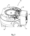
- FIG. 2 shown sectional view of the vacuum device 10 of the Fig. 1
- the cutting plane essentially runs through the lower part 16, the vacuum device 10 being rotated essentially by 180 °, that is to say the vacuum device from is considered below.
- Electronics 20 is visible, which itself, alternatively or in addition to the control unit 12, can form a control unit for accessory units connected to the connections 14.
- the control unit 12 can comprise, for example, an engine control.
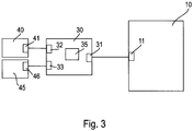
- Fig. 3 10 shows a system in which a connection device 30, which contains a communication control unit 35, is connected to a vacuum device 10 via a connection 11 on the vacuum device side and a connection 31 on the connection device side (in other words, first connection).
- the connection device contains further (in other words, second) connections 32, 33.
- Operating devices 40, 45 are connected to the second connections 32, 33 via the respective connections 41, 46 on the operating device side. More precisely, via a first second connection 32 and via a connection on the operating device side 41 of a first operating device 40, the first operating device 40 is connected to the connection device 30, and the second operating device 45 is connected to the connection device 30 via a second second connection 33 via a connection 46 on the operating device side of a second operating device 45.
- Fig. 4 shows a communication diagram showing the communication between the connection device 30, the vacuum device 10, the first operating device 40 and the second operating device 45.
- the first operating device 40 sends a first operating message 50.
- the first operating device 40 can send the first operating message 50 as if it were being sent to the vacuum device 10.
- the first operating message is received by the connecting device 30.
- the connection device 30 forwards the first operating message 50 to the vacuum device 10 as an operating message 52 (which, for example, can be preprocessed or filtered or can be identical to the first operating message 50).
- the vacuum device 10 processes the control message 52.
- the connection device 30 receives a second control message 56 from the second control device 45.
- the second control message 56 is activated in step 58 temporarily stored in the connection device 30.
- the vacuum device 10 sends a response 60 to the operating message 52 to the connection device 30.
- the connection device 30 sends the stored second operating message 56 in step 62 for transmission to the vacuum device 10 ready, and sends the second operating message 56 (possibly after preprocessing or filtering) as operating message 64 to the vacuum device 10.
- the vacuum device 10 processes the operating message 64 in step 66.
- connection device 30 forwards the answer 60 to the first operating device 40, for which the The response as the response of the vacuum device 10 to the first operating message 50 is actually determined, as the response 68 (possibly after preprocessing or filtering). Furthermore, the connection device 30 can also forward the message 60 to the second operating device 45 as a response 70 (possibly after preprocessing or filtering). Although in Figure 4 it is shown that the response 68, 70 to the first operating message 50 is only forwarded to the operating devices 40, 45 after the second operating message 56 has been forwarded to the vacuum device 10, the forwarding can also take place in a different order or, for example, simultaneously.
- the vacuum device 10 sends a response 72 to the second operating message 64 to the connection device 30.
- the connection device 30 forwards the answer 72 to the second operating device 45, for which the response is the response of the vacuum device 10 to the second operating message 64 is actually determined, as answer 74 (possibly after preprocessing or filtering). Further the connection device 30 can also forward the message 72 to the first operating device 40 as a response 76 (possibly after preprocessing or filtering).
Landscapes
- Engineering & Computer Science (AREA)
- Mechanical Engineering (AREA)
- General Engineering & Computer Science (AREA)
- Physics & Mathematics (AREA)
- General Physics & Mathematics (AREA)
- Compressors, Vaccum Pumps And Other Relevant Systems (AREA)
Priority Applications (1)
| Application Number | Priority Date | Filing Date | Title |
|---|---|---|---|
| EP19194579.9A EP3620661B1 (fr) | 2019-08-30 | 2019-08-30 | Dispositif de raccordement, système et procédé de fonctionnement d'un dispositif de raccordement |
Applications Claiming Priority (1)
| Application Number | Priority Date | Filing Date | Title |
|---|---|---|---|
| EP19194579.9A EP3620661B1 (fr) | 2019-08-30 | 2019-08-30 | Dispositif de raccordement, système et procédé de fonctionnement d'un dispositif de raccordement |
Publications (2)
| Publication Number | Publication Date |
|---|---|
| EP3620661A1 true EP3620661A1 (fr) | 2020-03-11 |
| EP3620661B1 EP3620661B1 (fr) | 2021-10-06 |
Family
ID=67810450
Family Applications (1)
| Application Number | Title | Priority Date | Filing Date |
|---|---|---|---|
| EP19194579.9A Active EP3620661B1 (fr) | 2019-08-30 | 2019-08-30 | Dispositif de raccordement, système et procédé de fonctionnement d'un dispositif de raccordement |
Country Status (1)
| Country | Link |
|---|---|
| EP (1) | EP3620661B1 (fr) |
Cited By (1)
| Publication number | Priority date | Publication date | Assignee | Title |
|---|---|---|---|---|
| EP3951738A3 (fr) * | 2021-12-13 | 2022-07-06 | Pfeiffer Vacuum Technology AG | Dispositif et procédé de communication doté d'un appareil sous vide |
Citations (2)
| Publication number | Priority date | Publication date | Assignee | Title |
|---|---|---|---|---|
| EP0809164A1 (fr) * | 1996-05-21 | 1997-11-26 | Ebara Corporation | Système de contrÔle pour contrÔler plusieurs pompes à vide |
| EP1903530A2 (fr) * | 2006-09-23 | 2008-03-26 | Pfeiffer Vacuum GmbH | Agencement doté d'un appareil sous vide et son procédé de fonctionnement |
Family Cites Families (1)
| Publication number | Priority date | Publication date | Assignee | Title |
|---|---|---|---|---|
| WO2018158917A1 (fr) * | 2017-03-02 | 2018-09-07 | 三菱電機株式会社 | Dispositif de commande, dispositif d'affichage, système de commande et procédé d'affichage de charge de processus |
-
2019
- 2019-08-30 EP EP19194579.9A patent/EP3620661B1/fr active Active
Patent Citations (2)
| Publication number | Priority date | Publication date | Assignee | Title |
|---|---|---|---|---|
| EP0809164A1 (fr) * | 1996-05-21 | 1997-11-26 | Ebara Corporation | Système de contrÔle pour contrÔler plusieurs pompes à vide |
| EP1903530A2 (fr) * | 2006-09-23 | 2008-03-26 | Pfeiffer Vacuum GmbH | Agencement doté d'un appareil sous vide et son procédé de fonctionnement |
Non-Patent Citations (1)
| Title |
|---|
| WILLIAM C GRAHAM ET AL: "Performance of Scheduling Strategies for ClienttServer Systems", JOURNAL OF PARALLEL AND DISTRIBUTED COMPUTING, 1 September 1999 (1999-09-01), XP055665023, Retrieved from the Internet <URL:https://www.sciencedirect.com/science/article/pii/S0743731599915617> * |
Cited By (2)
| Publication number | Priority date | Publication date | Assignee | Title |
|---|---|---|---|---|
| EP3951738A3 (fr) * | 2021-12-13 | 2022-07-06 | Pfeiffer Vacuum Technology AG | Dispositif et procédé de communication doté d'un appareil sous vide |
| EP3951738B1 (fr) | 2021-12-13 | 2023-12-13 | Pfeiffer Vacuum Technology AG | Appareil et procédé pour la communication avec un dispositif à vide |
Also Published As
| Publication number | Publication date |
|---|---|
| EP3620661B1 (fr) | 2021-10-06 |
Similar Documents
| Publication | Publication Date | Title |
|---|---|---|
| DE69123663T2 (de) | Kanäle in einem Rechnerein-Ausgabesystem | |
| DE69123104T2 (de) | Melden und Verifizieren von Zustandswechseln in einem Datenverarbeitungsein- / -ausgabesystem | |
| EP2825921B1 (fr) | Dispositif de commande pour la commande de processus critiques pour la sécurité dans une installation automatisée et procédé de paramétrisation du dispositif de commande | |
| EP3854028B1 (fr) | Procédé de détection d'abonnés du réseau dans un réseau d'automatisation et réseau d'automatisation | |
| DE4104601A1 (de) | Empfangsdatenverarbeitungsanlage | |
| DE112007002147T5 (de) | Fahrzeuginternes LAN-System, elektronische Steuereinheit, Vermittlungsverbindungseinheit und Fahrzeuginterne LAN-Kommunikationseinrichtung | |
| WO2001007974A1 (fr) | Procede de configuration d'un noeud | |
| DE68924051T2 (de) | Vielfacher Ein-/Ausgabe-Kanal. | |
| DE102019218045A1 (de) | Verfahren zur Überwachung der Kommunikation auf einem Kommunikationsbus, elektronische Vorrichtung zum Anschluss an einen Kommunikationsbus, sowie zentrale Überwachungsvorrichtung zum Anschluss an einen Kommunikationsbus | |
| EP3620661B1 (fr) | Dispositif de raccordement, système et procédé de fonctionnement d'un dispositif de raccordement | |
| EP0725516B1 (fr) | Procédé de détermination de position d'un participant dans un réseau | |
| EP1133106B1 (fr) | Dispositif de commande d'échange de données dans un terminal de communication | |
| EP3632049B1 (fr) | Émission de signal d'état | |
| EP1642207B1 (fr) | Attribution d'adresses de station a des abonnes de communication dans un systeme de bus | |
| EP3632054B1 (fr) | Determination de noeuds d'un bus de données local | |
| EP3632056B1 (fr) | Intitialisation d'un bus local | |
| WO2011072958A1 (fr) | Procédé d'attribution d'une adresse d'interrogation à un appareil de terrain | |
| DE10037969C2 (de) | Verfahren zur Erkennung einer flexiblen Vernetzung von Baugruppen bei beliebiger Netztopologie sowie zum Informationsaustausch zwischen solchen Baugruppen | |
| DE102019110884A1 (de) | Verfahren zur Änderung einer Steuerungssoftware eines Automatisierungssystems | |
| DE102021213001B3 (de) | Verfahren zum Betreiben eines Feldbussystems und Feldbussystem | |
| WO2012025323A1 (fr) | Procédé de transmission d'une communication | |
| DE102019218061A1 (de) | Weiterleitungsgerät | |
| EP2183902B1 (fr) | Procédé pour détecter une attaque de déni de service et terminal de communication | |
| EP1430647B1 (fr) | Prodédé pour exploiter un noeud de commutation dans unréseau de transmission de données | |
| DE602005005025T2 (de) | Gateway und datenübertragungssystem für das diagnostische netzwerk eines kraftfahrzeugs |
Legal Events
| Date | Code | Title | Description |
|---|---|---|---|
| PUAI | Public reference made under article 153(3) epc to a published international application that has entered the european phase |
Free format text: ORIGINAL CODE: 0009012 |
|
| STAA | Information on the status of an ep patent application or granted ep patent |
Free format text: STATUS: THE APPLICATION HAS BEEN PUBLISHED |
|
| AK | Designated contracting states |
Kind code of ref document: A1 Designated state(s): AL AT BE BG CH CY CZ DE DK EE ES FI FR GB GR HR HU IE IS IT LI LT LU LV MC MK MT NL NO PL PT RO RS SE SI SK SM TR |
|
| STAA | Information on the status of an ep patent application or granted ep patent |
Free format text: STATUS: REQUEST FOR EXAMINATION WAS MADE |
|
| 17P | Request for examination filed |
Effective date: 20200910 |
|
| RBV | Designated contracting states (corrected) |
Designated state(s): AL AT BE BG CH CY CZ DE DK EE ES FI FR GB GR HR HU IE IS IT LI LT LU LV MC MK MT NL NO PL PT RO RS SE SI SK SM TR |
|
| STAA | Information on the status of an ep patent application or granted ep patent |
Free format text: STATUS: EXAMINATION IS IN PROGRESS |
|
| 17Q | First examination report despatched |
Effective date: 20201105 |
|
| GRAP | Despatch of communication of intention to grant a patent |
Free format text: ORIGINAL CODE: EPIDOSNIGR1 |
|
| STAA | Information on the status of an ep patent application or granted ep patent |
Free format text: STATUS: GRANT OF PATENT IS INTENDED |
|
| INTG | Intention to grant announced |
Effective date: 20210519 |
|
| GRAS | Grant fee paid |
Free format text: ORIGINAL CODE: EPIDOSNIGR3 |
|
| GRAA | (expected) grant |
Free format text: ORIGINAL CODE: 0009210 |
|
| STAA | Information on the status of an ep patent application or granted ep patent |
Free format text: STATUS: THE PATENT HAS BEEN GRANTED |
|
| AK | Designated contracting states |
Kind code of ref document: B1 Designated state(s): AL AT BE BG CH CY CZ DE DK EE ES FI FR GB GR HR HU IE IS IT LI LT LU LV MC MK MT NL NO PL PT RO RS SE SI SK SM TR |
|
| REG | Reference to a national code |
Ref country code: GB Ref legal event code: FG4D Free format text: NOT ENGLISH |
|
| REG | Reference to a national code |
Ref country code: CH Ref legal event code: EP Ref country code: AT Ref legal event code: REF Ref document number: 1436470 Country of ref document: AT Kind code of ref document: T Effective date: 20211015 |
|
| REG | Reference to a national code |
Ref country code: DE Ref legal event code: R096 Ref document number: 502019002444 Country of ref document: DE |
|
| REG | Reference to a national code |
Ref country code: IE Ref legal event code: FG4D Free format text: LANGUAGE OF EP DOCUMENT: GERMAN |
|
| REG | Reference to a national code |
Ref country code: LT Ref legal event code: MG9D |
|
| REG | Reference to a national code |
Ref country code: NL Ref legal event code: MP Effective date: 20211006 |
|
| PG25 | Lapsed in a contracting state [announced via postgrant information from national office to epo] |
Ref country code: RS Free format text: LAPSE BECAUSE OF FAILURE TO SUBMIT A TRANSLATION OF THE DESCRIPTION OR TO PAY THE FEE WITHIN THE PRESCRIBED TIME-LIMIT Effective date: 20211006 Ref country code: LT Free format text: LAPSE BECAUSE OF FAILURE TO SUBMIT A TRANSLATION OF THE DESCRIPTION OR TO PAY THE FEE WITHIN THE PRESCRIBED TIME-LIMIT Effective date: 20211006 Ref country code: FI Free format text: LAPSE BECAUSE OF FAILURE TO SUBMIT A TRANSLATION OF THE DESCRIPTION OR TO PAY THE FEE WITHIN THE PRESCRIBED TIME-LIMIT Effective date: 20211006 Ref country code: BG Free format text: LAPSE BECAUSE OF FAILURE TO SUBMIT A TRANSLATION OF THE DESCRIPTION OR TO PAY THE FEE WITHIN THE PRESCRIBED TIME-LIMIT Effective date: 20220106 |
|
| PG25 | Lapsed in a contracting state [announced via postgrant information from national office to epo] |
Ref country code: IS Free format text: LAPSE BECAUSE OF FAILURE TO SUBMIT A TRANSLATION OF THE DESCRIPTION OR TO PAY THE FEE WITHIN THE PRESCRIBED TIME-LIMIT Effective date: 20220206 Ref country code: SE Free format text: LAPSE BECAUSE OF FAILURE TO SUBMIT A TRANSLATION OF THE DESCRIPTION OR TO PAY THE FEE WITHIN THE PRESCRIBED TIME-LIMIT Effective date: 20211006 Ref country code: PT Free format text: LAPSE BECAUSE OF FAILURE TO SUBMIT A TRANSLATION OF THE DESCRIPTION OR TO PAY THE FEE WITHIN THE PRESCRIBED TIME-LIMIT Effective date: 20220207 Ref country code: PL Free format text: LAPSE BECAUSE OF FAILURE TO SUBMIT A TRANSLATION OF THE DESCRIPTION OR TO PAY THE FEE WITHIN THE PRESCRIBED TIME-LIMIT Effective date: 20211006 Ref country code: NO Free format text: LAPSE BECAUSE OF FAILURE TO SUBMIT A TRANSLATION OF THE DESCRIPTION OR TO PAY THE FEE WITHIN THE PRESCRIBED TIME-LIMIT Effective date: 20220106 Ref country code: NL Free format text: LAPSE BECAUSE OF FAILURE TO SUBMIT A TRANSLATION OF THE DESCRIPTION OR TO PAY THE FEE WITHIN THE PRESCRIBED TIME-LIMIT Effective date: 20211006 Ref country code: LV Free format text: LAPSE BECAUSE OF FAILURE TO SUBMIT A TRANSLATION OF THE DESCRIPTION OR TO PAY THE FEE WITHIN THE PRESCRIBED TIME-LIMIT Effective date: 20211006 Ref country code: HR Free format text: LAPSE BECAUSE OF FAILURE TO SUBMIT A TRANSLATION OF THE DESCRIPTION OR TO PAY THE FEE WITHIN THE PRESCRIBED TIME-LIMIT Effective date: 20211006 Ref country code: GR Free format text: LAPSE BECAUSE OF FAILURE TO SUBMIT A TRANSLATION OF THE DESCRIPTION OR TO PAY THE FEE WITHIN THE PRESCRIBED TIME-LIMIT Effective date: 20220107 Ref country code: ES Free format text: LAPSE BECAUSE OF FAILURE TO SUBMIT A TRANSLATION OF THE DESCRIPTION OR TO PAY THE FEE WITHIN THE PRESCRIBED TIME-LIMIT Effective date: 20211006 |
|
| REG | Reference to a national code |
Ref country code: DE Ref legal event code: R097 Ref document number: 502019002444 Country of ref document: DE |
|
| PG25 | Lapsed in a contracting state [announced via postgrant information from national office to epo] |
Ref country code: SM Free format text: LAPSE BECAUSE OF FAILURE TO SUBMIT A TRANSLATION OF THE DESCRIPTION OR TO PAY THE FEE WITHIN THE PRESCRIBED TIME-LIMIT Effective date: 20211006 Ref country code: SK Free format text: LAPSE BECAUSE OF FAILURE TO SUBMIT A TRANSLATION OF THE DESCRIPTION OR TO PAY THE FEE WITHIN THE PRESCRIBED TIME-LIMIT Effective date: 20211006 Ref country code: RO Free format text: LAPSE BECAUSE OF FAILURE TO SUBMIT A TRANSLATION OF THE DESCRIPTION OR TO PAY THE FEE WITHIN THE PRESCRIBED TIME-LIMIT Effective date: 20211006 Ref country code: EE Free format text: LAPSE BECAUSE OF FAILURE TO SUBMIT A TRANSLATION OF THE DESCRIPTION OR TO PAY THE FEE WITHIN THE PRESCRIBED TIME-LIMIT Effective date: 20211006 Ref country code: DK Free format text: LAPSE BECAUSE OF FAILURE TO SUBMIT A TRANSLATION OF THE DESCRIPTION OR TO PAY THE FEE WITHIN THE PRESCRIBED TIME-LIMIT Effective date: 20211006 |
|
| PLBE | No opposition filed within time limit |
Free format text: ORIGINAL CODE: 0009261 |
|
| STAA | Information on the status of an ep patent application or granted ep patent |
Free format text: STATUS: NO OPPOSITION FILED WITHIN TIME LIMIT |
|
| 26N | No opposition filed |
Effective date: 20220707 |
|
| PG25 | Lapsed in a contracting state [announced via postgrant information from national office to epo] |
Ref country code: AL Free format text: LAPSE BECAUSE OF FAILURE TO SUBMIT A TRANSLATION OF THE DESCRIPTION OR TO PAY THE FEE WITHIN THE PRESCRIBED TIME-LIMIT Effective date: 20211006 |
|
| PG25 | Lapsed in a contracting state [announced via postgrant information from national office to epo] |
Ref country code: SI Free format text: LAPSE BECAUSE OF FAILURE TO SUBMIT A TRANSLATION OF THE DESCRIPTION OR TO PAY THE FEE WITHIN THE PRESCRIBED TIME-LIMIT Effective date: 20211006 |
|
| PG25 | Lapsed in a contracting state [announced via postgrant information from national office to epo] |
Ref country code: MC Free format text: LAPSE BECAUSE OF FAILURE TO SUBMIT A TRANSLATION OF THE DESCRIPTION OR TO PAY THE FEE WITHIN THE PRESCRIBED TIME-LIMIT Effective date: 20211006 |
|
| REG | Reference to a national code |
Ref country code: CH Ref legal event code: PL |
|
| PG25 | Lapsed in a contracting state [announced via postgrant information from national office to epo] |
Ref country code: LU Free format text: LAPSE BECAUSE OF NON-PAYMENT OF DUE FEES Effective date: 20220830 Ref country code: LI Free format text: LAPSE BECAUSE OF NON-PAYMENT OF DUE FEES Effective date: 20220831 Ref country code: CH Free format text: LAPSE BECAUSE OF NON-PAYMENT OF DUE FEES Effective date: 20220831 |
|
| REG | Reference to a national code |
Ref country code: BE Ref legal event code: MM Effective date: 20220831 |
|
| PG25 | Lapsed in a contracting state [announced via postgrant information from national office to epo] |
Ref country code: IE Free format text: LAPSE BECAUSE OF NON-PAYMENT OF DUE FEES Effective date: 20220830 Ref country code: FR Free format text: LAPSE BECAUSE OF NON-PAYMENT OF DUE FEES Effective date: 20220831 |
|
| PG25 | Lapsed in a contracting state [announced via postgrant information from national office to epo] |
Ref country code: BE Free format text: LAPSE BECAUSE OF NON-PAYMENT OF DUE FEES Effective date: 20220831 |
|
| PG25 | Lapsed in a contracting state [announced via postgrant information from national office to epo] |
Ref country code: HU Free format text: LAPSE BECAUSE OF FAILURE TO SUBMIT A TRANSLATION OF THE DESCRIPTION OR TO PAY THE FEE WITHIN THE PRESCRIBED TIME-LIMIT; INVALID AB INITIO Effective date: 20190830 |
|
| PG25 | Lapsed in a contracting state [announced via postgrant information from national office to epo] |
Ref country code: CY Free format text: LAPSE BECAUSE OF FAILURE TO SUBMIT A TRANSLATION OF THE DESCRIPTION OR TO PAY THE FEE WITHIN THE PRESCRIBED TIME-LIMIT Effective date: 20211006 |
|
| PG25 | Lapsed in a contracting state [announced via postgrant information from national office to epo] |
Ref country code: MK Free format text: LAPSE BECAUSE OF FAILURE TO SUBMIT A TRANSLATION OF THE DESCRIPTION OR TO PAY THE FEE WITHIN THE PRESCRIBED TIME-LIMIT Effective date: 20211006 |
|
| PG25 | Lapsed in a contracting state [announced via postgrant information from national office to epo] |
Ref country code: TR Free format text: LAPSE BECAUSE OF FAILURE TO SUBMIT A TRANSLATION OF THE DESCRIPTION OR TO PAY THE FEE WITHIN THE PRESCRIBED TIME-LIMIT Effective date: 20211006 |
|
| PG25 | Lapsed in a contracting state [announced via postgrant information from national office to epo] |
Ref country code: MT Free format text: LAPSE BECAUSE OF FAILURE TO SUBMIT A TRANSLATION OF THE DESCRIPTION OR TO PAY THE FEE WITHIN THE PRESCRIBED TIME-LIMIT Effective date: 20211006 |
|
| PGFP | Annual fee paid to national office [announced via postgrant information from national office to epo] |
Ref country code: IT Payment date: 20250825 Year of fee payment: 7 |
|
| REG | Reference to a national code |
Ref country code: AT Ref legal event code: MM01 Ref document number: 1436470 Country of ref document: AT Kind code of ref document: T Effective date: 20240830 |
|
| PGFP | Annual fee paid to national office [announced via postgrant information from national office to epo] |
Ref country code: GB Payment date: 20250820 Year of fee payment: 7 |
|
| PG25 | Lapsed in a contracting state [announced via postgrant information from national office to epo] |
Ref country code: AT Free format text: LAPSE BECAUSE OF NON-PAYMENT OF DUE FEES Effective date: 20240830 |
|
| PGFP | Annual fee paid to national office [announced via postgrant information from national office to epo] |
Ref country code: CZ Payment date: 20250827 Year of fee payment: 7 |
|
| PGFP | Annual fee paid to national office [announced via postgrant information from national office to epo] |
Ref country code: DE Payment date: 20251029 Year of fee payment: 7 |
|
| PGFP | Annual fee paid to national office [announced via postgrant information from national office to epo] |
Ref country code: AT Payment date: 20260410 Year of fee payment: 5 |