EP1905646B1 - Recouvrement de l'espace de chargement à ouverture automatique - Google Patents
Recouvrement de l'espace de chargement à ouverture automatique Download PDFInfo
- Publication number
- EP1905646B1 EP1905646B1 EP07015762A EP07015762A EP1905646B1 EP 1905646 B1 EP1905646 B1 EP 1905646B1 EP 07015762 A EP07015762 A EP 07015762A EP 07015762 A EP07015762 A EP 07015762A EP 1905646 B1 EP1905646 B1 EP 1905646B1
- Authority
- EP
- European Patent Office
- Prior art keywords
- cargo area
- area cover
- cover according
- guide rail
- guide groove
- Prior art date
- Legal status (The legal status is an assumption and is not a legal conclusion. Google has not performed a legal analysis and makes no representation as to the accuracy of the status listed.)
- Not-in-force
Links
Images


Classifications
-
- B—PERFORMING OPERATIONS; TRANSPORTING
- B60—VEHICLES IN GENERAL
- B60R—VEHICLES, VEHICLE FITTINGS, OR VEHICLE PARTS, NOT OTHERWISE PROVIDED FOR
- B60R5/00—Compartments within vehicle body primarily intended or sufficiently spacious for trunks, suit-cases, or the like
- B60R5/04—Compartments within vehicle body primarily intended or sufficiently spacious for trunks, suit-cases, or the like arranged at rear of vehicle
- B60R5/044—Compartments within vehicle body primarily intended or sufficiently spacious for trunks, suit-cases, or the like arranged at rear of vehicle luggage covering means, e.g. parcel shelves
- B60R5/045—Compartments within vehicle body primarily intended or sufficiently spacious for trunks, suit-cases, or the like arranged at rear of vehicle luggage covering means, e.g. parcel shelves collapsible or transformable
- B60R5/047—Compartments within vehicle body primarily intended or sufficiently spacious for trunks, suit-cases, or the like arranged at rear of vehicle luggage covering means, e.g. parcel shelves collapsible or transformable collapsible by rolling-up
-
- B—PERFORMING OPERATIONS; TRANSPORTING
- B60—VEHICLES IN GENERAL
- B60J—WINDOWS, WINDSCREENS, NON-FIXED ROOFS, DOORS, OR SIMILAR DEVICES FOR VEHICLES; REMOVABLE EXTERNAL PROTECTIVE COVERINGS SPECIALLY ADAPTED FOR VEHICLES
- B60J3/00—Antiglare equipment associated with windows or windscreens; Sun visors for vehicles
- B60J3/02—Antiglare equipment associated with windows or windscreens; Sun visors for vehicles adjustable in position
-
- B—PERFORMING OPERATIONS; TRANSPORTING
- B60—VEHICLES IN GENERAL
- B60J—WINDOWS, WINDSCREENS, NON-FIXED ROOFS, DOORS, OR SIMILAR DEVICES FOR VEHICLES; REMOVABLE EXTERNAL PROTECTIVE COVERINGS SPECIALLY ADAPTED FOR VEHICLES
- B60J1/00—Windows; Windscreens; Accessories therefor
- B60J1/20—Accessories, e.g. wind deflectors, blinds
-
- B—PERFORMING OPERATIONS; TRANSPORTING
- B60—VEHICLES IN GENERAL
- B60J—WINDOWS, WINDSCREENS, NON-FIXED ROOFS, DOORS, OR SIMILAR DEVICES FOR VEHICLES; REMOVABLE EXTERNAL PROTECTIVE COVERINGS SPECIALLY ADAPTED FOR VEHICLES
- B60J1/00—Windows; Windscreens; Accessories therefor
- B60J1/20—Accessories, e.g. wind deflectors, blinds
- B60J1/2011—Blinds; curtains or screens reducing heat or light intensity
- B60J1/2013—Roller blinds
- B60J1/2036—Roller blinds characterised by structural elements
- B60J1/2058—Springs for compensating the number of windings of the blind on the tube in case winding tube and draw bar are driven together
-
- B—PERFORMING OPERATIONS; TRANSPORTING
- B60—VEHICLES IN GENERAL
- B60J—WINDOWS, WINDSCREENS, NON-FIXED ROOFS, DOORS, OR SIMILAR DEVICES FOR VEHICLES; REMOVABLE EXTERNAL PROTECTIVE COVERINGS SPECIALLY ADAPTED FOR VEHICLES
- B60J3/00—Antiglare equipment associated with windows or windscreens; Sun visors for vehicles
Definitions
- a contour plate with a handle.
- the contours can be detected by hand and moved while pulling the roller blind towards the rear opening. There, the contour plate is hooked with laterally projecting pin accordingly.
- the spring motor keeps the roller blind under tension.
- the actuators To drive the actuators are two electric motors. However, the electric motors are electrically synchronized with each other.
- the DE 198 25 353 A1 describes a load compartment cover in which the roller blind is only to move horizontally.
- the roller blind is only to move horizontally.
- the side edges of the cargo bay run two guide rails, with which end pieces of the Kontjuds be worn and guided.
- each of the guide rails at the front and at the rear end pulleys in the form of pulleys intended.
- About each of the two discs of a guide rail is an endless toothed belt around, carries the upward pointing Hätrum a coupling part for the lateral pin of Konturchs.
- the pulley facing the front end of the cargo bay is driven by its own electric motor. Both motors are electrically synchronized via an elaborate synchronizing circuit during their run in order to exclude a skew of the Kontitess in the opening or closing movement with certainty.
- the electrical synchronization is technically complex and requires gear motors that contain additional signal generator to allow electrical synchronization.
- the new cargo compartment cover is used in the usual way to close the upper access opening of a cargo bay of a station wagon.
- To the load compartment cover includes a rotatably mounted winding shaft, to which a roller blind is attached with one edge.
- the roller blind can be manually moved back and forth between an open position and a closed position. In the open position, the loading bay is fully open, while in the closed position, apart from the opening, which otherwise closes the tailgate, is closed.
- an intermediate position in which the roller blind is brought automatically when opening the tailgate.
- a pull-out profile for example in the form of a contour plate, attached.
- This pull-out profile is guided in two guide rail arrangements which only extend one along a path followed by the pull-out profile when it is moved to the intermediate position starting from the closed position.
- linear actuators are provided, one of which is guided in the one guide rail assembly and the other in the other guide rail assembly.
- Each geared motor is a permanent-magnet DC motor.
- the two motors are mechanically and electrically decoupled and the assembly is totally free of any electrical or mechanical devices that synchronize their movement with each other during the running of the motors.
- the two geared motors run, apart from the simultaneous switching, completely autonomous.
- the electrical circuit complexity remains low because electrical synchronizers are missing. Since there are no mechanical synchronizers and each actuator is driven by itself, The friction losses remained small, because the drive motors can be provided immediately adjacent to the guide rail assemblies.
- the guide rails are also mounted in the D-pillar and range from a location corresponding to the closed position of the cargo space cover to near the top of the rear opening.
- the other possibility for the intermediate position is on the way between the closed position and the full open position.
- the guide rail arrangements starting at the rear opening, a piece far in the direction of the rear seat.
- actuators carry a toothing on the outside.
- Such actuators can be driven by geared motors which carry on their output shaft a corresponding gear which is in positive engagement with the toothing. Any stroke differences due to slippage are thus efficiently excluded.
- the guide rail assemblies were each composed of a first guide groove and a second guide groove.
- the first guide groove runs a pin or extension of the extension profile and a coupling element for this purpose.
- the second guide groove is the actuator, which is out there, depending on the embodiment, for example, also ausknickêt.
- the coupling element Via a slot which connects the two guide grooves, the coupling element is connected to the actuator by an intermediate piece.
- the first guide groove may be slit-shaped, i. it is bounded by two flanks and a back wall.
- Another possibility, which is particularly suitable for the horizontally extending guide rail assembly, is to provide the first guide groove with only two angularly extending walls, so that the guide groove is open both upwards and towards the opposite side of the vehicle. This makes it possible to unhook the roller blind at any point from the coupling member and manually transfer to the full open position.
- This design of the guide rail assembly is basically also for the design with guide rail assemblies in the D-pillar in question.
- the coupling part which connects the actuator to the extension profile can, in the simplest case, have a forked shape which has two legs which delimit a slot-shaped opening. Depending on the position of the guide rail arrangement, this opening can point in the direction parallel to the movement and away from the winding shaft, or the opening may be oriented orthogonal to the direction of movement. The latter is in the accommodation of the guide rail assembly in the D-pillar in question.
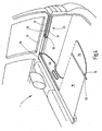
- Fig. 1 shows a section of a rear end 1 of a station wagon 2. It can be seen the rear opening 3, which is bounded by a lower edge 4, a side edge 5, an upper edge 6 and another, to the side edge 5 mirror image but broken edge.
- the side edge 5 is formed in the upper region by a D-pillar 7.
- a tailgate 8 is hinged.
- the estate car 2 contains in its interior an approximately rectangular cargo bay 9, which is bounded by a bottom 10, a right side wall 11, the back of a rear seat back 12 and another to the side wall 11 mirror image left side wall.
- the two side walls 11 terminate at a lower edge of the window 13, above which a rear side window 14 can be seen.
- a cargo space cover 15 is provided to which belongs a cassette-type elongated housing from which a roller blind 18 can be pulled out of a slot 17.
- a winding shaft is rotatably mounted, which is biased by a spring motor in the winding direction of the roller blind.
- the roller blind 18 has a rectangular blank, corresponding to the rectangular upper opening of the loading bay.
- a pull rod 19 is attached, which is approximately centrally a handle loop 21st wearing.
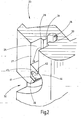
- the tension rod 19 has lateral, over the roller blind 18 protruding pin 22, which serve to guide the pull rod 19 in guide rail assemblies 23 which are parallel to each other and whose structure is apparent from the sectional view of Fig. 2 results.
- the guide rail assembly 23 is included in the region of the D-pillar 7 and starts below about a height at which the lower edge of the window 17 is located.
- the guide rail assembly 23 follows the course of the D-pillar 7 upwards.
- the guide rail assembly 23 may for example be integrated in the interior trim part of the D-pillar 7. She sits down, like Fig. 2 can recognize, from a first guide groove 25 and a second guide groove 26 together.
- the guide groove 25 is bounded by two mutually parallel side walls 27 and 28 and a rear wall 29.
- the two side walls 27 and 28 are parallel to each other and have a distance from each other corresponding approximately to the diameter of the pin 22.
- the guide groove 25 opens in the direction of the opposite, broken away side edge.
- the guide groove 26 is composed in cross section of a groove chamber 30 and a groove slot 31.
- the groove chamber 30 has a circular cross section, while the groove slot 31 is rectangular. He connects, as the figure can be seen, the groove chamber 30 with the first guide groove 25, for which he opens centrally in the rear wall 29.
- a corresponding guide rail assembly 23 is located in a mirror image in the broken D-pillar.
- the guide groove 25 forms an inlet funnel 32, the opening points in the direction of the rear seat back 12. Starting from the pointing in the direction of the rear seat back 12 opening of the inlet funnel 32 runs with reduced width by an angle of about 180 °, then at the lower end through the wall 28 into the guide groove 25.
- the drive concept of the load compartment cover 15 results from Fig. 3 ,
- the two guide rail arrangements 23 can be seen right and left of the roller blind 18.
- the right guide rail assembly 23 is shown closed, while the left guide rail assembly 23 is partially broken.
- the first guide groove 25 with its side wall 27 lying to the vehicle can be seen, also a wall of the slot 31 and the circular groove chamber 30.
- the groove chamber 30 serves to ausknickêt a line-shaped actuator 35 to lead, which transmits pressure and tensile forces.
- the actuating element 33 is composed of a flexible cylindrical core 34 and a helix 35 fixed immovably thereto. This creates a kind of helical toothed rack, which is flexible. Since it is guided in the chamber 39 with little radial play, can not buckle laterally and is able to transmit pressure forces.
- a corresponding linear actuator 33 also runs in the right guide rail assembly 23.
- a coupling member 36 is present, which is rigidly connected via a neck portion 37, which passes through the slot 31 with a slider 38.
- the slider 38 is a cylindrical member slidably guided in the chamber 29.
- the slider 38 is tension and compression resistant connected to the upper end of the linear actuator 33 so that can be transmitted from the actuator 33 tensile and compressive forces on the coupling member 36.
- the coupling part 36 has the shape of a fork with two legs 41 and 42, which are connected to each other via a back portion 43.
- the two legs 41 and 42 define an approximately parallel-flared mouth 44, which in the direction of the wall 28, ie in the direction of the rear opening 3, shows.
- the two legs 41 and 42 are interconnected by a wall 45 from which the connector 37 extends.
- the coupling part 36 is approximately cuboid. It almost completely fills the guide groove 25 as shown.
- the stroke of the coupling part 36 is bounded below by a stop surface 46 which projects at right angles from the wall 25 and forms part of the inlet funnel 32.
- a corresponding stop is provided at the upper end of the guide rail assembly 23, simply in the form of the there closed end of the guide groove 25th
- each guide rail assembly 23 each have their own geared motor 48 a and 48 b provided.
- the two geared motors 48a and 48b are identical in construction and optionally mirror-symmetrical and each have their own output shaft 49a or 49b.
- a spur gear 51a On the output shaft 49a sits a spur gear 51a, which is designed so that it can be brought into positive engagement with the linear actuator 33 in engagement.
- the spur gear 51a runs in a housing and the actuator 41 is passed through a bore in the housing tangentially to the spur gear 51a and held in engagement therewith.
- these gear housings are omitted in both gearmotors 48a and 48b.
- the protruding part of the actuator 33 runs as a return strand in a storage tube 52 a, which can be laid arbitrarily behind the side panel of the side wall 11.
- the two geared motors 48a and 48b are each connected individually to a common, schematically indicated switch 53, with the aid of which they can be connected with one or the other polarity to the electrical system of the motor vehicle.
- the connecting lines are indicated by dashed lines at 54a and 54b.
- the switch 53 is shown only schematically and is actuated by the movement of the tailgate 8.
- the switch can also be replaced by a relay control whose input button is also connected to the tailgate 8.
- the circuit diagram is not illustrated because it is neither the subject of the invention nor essential for the understanding of the invention.
- a winding shaft is rotatably mounted, on which the respective edge of the blind sheet 18 is attached.
- the winding shaft is biased in a known manner by means of a spring motor in the winding direction of the roller blind 18.
- roller blind 18 In the open or open position, the roller blind 18 is completely wound onto the winding shaft in the cassette housing 16.
- the pull rod 19 abuts against the slot of the cassette housing 16.
- the control for the cargo cover 15 is switched to manual operation, which means that the coupling parts 36 in the two guide rail assemblies 23 in the lower position according to Fig. 2 stand, regardless of whether the tailgate 3 is open or closed.
- the user can grasp the loop 21 at will and move the pull rod 19 toward him toward the tailgate opening 3.
- the two laterally projecting pins 22 via the present at each guide rail assembly 23 inlet hopper 32 in the mouth 44 of each coupling part 36 hang. This position is the closed position in which the cargo bay 9 is protected from the top against view.
- the cargo bay After closing the tailgate 8, the cargo bay, as far as it is only used to the lower edge of the window, closed on all sides.
- the electronics present in the vehicle ensure that the switch 53 is actuated, depending on the position or movement of the tailgate 8.
- the pre-operating position also remains in the setting the cargo space cover in the lower position in which the blind sheet 18 extends substantially horizontally.
- the two geared motors 48a and 48b are switched on the controlled switch 53 simultaneously. They move in one direction of rotation so that the two motors 48a and 48b are practically synchronized with the actuators 33 coupled to them via the gears 51a and 51b Fig. 2 shown lower position in the in Fig. 1 move illustrated upper position.
- the controlled switch 53 When the user closes the tailgate 8, the controlled switch 53 is moved in the opposite direction, whereby the two geared motors are connected in opposite polarity with the electrical system of the motor vehicle. They turn in the opposite direction and pull the actuators 33 back to the position according to Fig. 2 , Here, the extended blind sheet 18 is pivoted down and comes out of the in Fig. 1 shown comfort opening position in the closed position.
- the two geared motors 48a and 48b are electrically and mechanically unsynchronized, i. Each of the two geared motors 48a, 48b runs at its own actual speed. These speeds will be very close to each other, since the motors are identical and have the same rated speed.
- the advantage of this arrangement is that the motors 48 can be located immediately below the lower end of the guide rail assembly 23 on each motor vehicle side behind the side trim.
- Engine operation can not produce disturbing body resonances.
- the working length of the actuators 33 is short and there are hardly any friction losses.
- the storage tube for the return strand can be kept correspondingly short. It can consist of a flexible hose, which can be laid largely freely in the vehicle. In any case, it is not necessary to preform the storage tube in a special way.
- the new solution saves complex electrical synchronizations or the mechanical coupling between the two actuators 33, which would be difficult to install and also provides additional friction losses.
- Fig. 4 shows an alternative embodiment, wherein the comfort position lies in the plane defined by the open and the closed position.
- the main difference is limited to the fact that the guide rail assembly 23 is no longer housed in the D-pillar 7, but it runs as Fig. 4
- the guide rail assembly 23 has a length approximately equal to half the stroke, which the pull rod 19, which is here provided with a contour plate 56, covers when it is moved back and forth between the open and closed positions ,
- the guide rail assembly 23 differs from the embodiment Fig. 2 in that only the one side wall 27 is present as the lower side wall and the rear wall 29. In the rear wall 29 of the slot 31 can be seen, behind which the second guide groove 26 extends.
- the wall 27 simultaneously forms a sliding and bearing surface for the coupling part 36, which in Fig. 4 shown in the comfort position.
- the guide rail assembly 23 has a reaching to the cassette housing 16 extension in which, for example, the respective geared motor 48 and the storage tube 52 can be accommodated for the return strand.
- Fig. 4 shows in the upper right half of the load compartment cover 15 in the open position. In this position, as already mentioned, the pull rod 19 abuts against the slot 17 of the cassette housing 16.
- the lower left partial view illustrates the cargo cover 15 in the closed position.
- the roller blind 18 is pulled out to the maximum, so that the pull rod 19 is in the vicinity of the rear opening 3.
- the contours 56 closes the possibly segment-shaped gap between the straight drawbar 19 and the inside of the tailgate. 8
- the structure of the guide rail assembly 23 is mutatis mutandis the same, as in connection with Fig.2 has already been explained in detail, only with the difference that the guide rail assembly 23 extends horizontally and instead of the slot-shaped groove as a guide groove 25 only an L-shaped groove is provided which consists of the lower wall and the rear wall.
- the dome part 36 is in the same way as in Fig. 2 mechanically connected to the associated actuator.
- the pin 52 hangs by a short movement towards the rear opening 3 and then the blind, as in a normal only manually operated blind in the direction of the Cartridge housing 16 moves.
- the arrangement after Fig. 4 has the advantage that the user can still use the partially extended blind sheet 18 in the intermediate position as a clipboard when he wants to unload or load the loading bay 3.
- roller blind rail arrangements are provided on both sides of the roller blind rail in order to bring the roller blind web, starting from the closed position, into a comfort position.
- two separate geared motors are provided which are not synchronized with each other. They run electrically and mechanically completely independently of each other.
Landscapes
- Engineering & Computer Science (AREA)
- Mechanical Engineering (AREA)
- Operating, Guiding And Securing Of Roll- Type Closing Members (AREA)
- Power-Operated Mechanisms For Wings (AREA)
- Vehicle Step Arrangements And Article Storage (AREA)
- Window Of Vehicle (AREA)
- Air-Flow Control Members (AREA)
- Forklifts And Lifting Vehicles (AREA)
Claims (17)
- Dispositif de recouvrement d'espace à bagages, destiné à fermer l'ouverture d'accès supérieure d'un espace à bagages (9) d'une voiture particulière de type break, dotée d'une ouverture arrière (3),
comprenant un arbre d'enroulement monté tournant,
comprenant une bande de store (18),- qui est fixée avec un bord à l'axe d'enroulement,- qui peut être déplacée entre une position d'ouverture et une position de fermeture et vice versa, et- qui peut être amenée dans une position intermédiaire,- l'espace à bagages (9) étant complètement fermé vers le haut en position de fermeture, et étant ouvert au maximum en position d'ouverture, tandis que l'espace à bagages (9) est ouvert partiellement dans la position intermédiaire,comprenant un profilé de traction (19) qui est fixé à un bord de la bande de store (18) éloigné de l'axe d'enroulement,
comprenant deux systèmes de rail de guidage (23) qui s'étendent seulement le long d'un chemin que suit le profilé de traction (19) lorsque, partant de la position de fermeture, il est amené dans la position intermédiaire,
comprenant deux éléments d'actionnement (33) linéaires, dont l'un est guidé dans un système de rail de guidage (23) et l'autre dans l'autre système de rail de guidage (23),
comprenant deux tubes de rangement (52) pour recevoir le tronçon non chargé respectif de l'élément d'actionnement (33),
comprenant des butées (46) à complémentarité de forme, destinées à limiter la course des éléments d'actionnement (23),
comprenant deux éléments d'accouplement (36), à l'aide desquels un élément d'actionnement (33) respectif peut être accouplé avec complémentarité de formes à une extrémité du profilé de traction (19), au moins par rapport à une direction de déplacement, caractérisé par le fait que les deux tubes de rangement sont réalisés chacun sous forme de tuyau souple, et par le fait que le dispositif de recouvrement d'espace à bagages présente deux motoréducteurs (48),- qui fonctionnent avec la même vitesse de rotation nominale,- qui comportent chacun un moteur à courant continu excité en permanence, et
les deux motoréducteurs (48) travaillant indépendamment l'un de l'autre sur les plans mécanique et électrique, et le dispositif est dépourvu d'installations pour synchroniser électriquement les motoréducteurs (48) pendant leur fonctionnement. - Dispositif de recouvrement d'espace à bagages selon la revendication 1, caractérisé par le fait que chaque système de rail de guidage (23) s'étend au moins sur une certaine distance en direction du toit de la voiture particulière de type break, à proximité d'un côté (5) de l'ouverture arrière (3) du break.
- Dispositif de recouvrement d'espace à bagages selon la revendication 1, caractérisé par le fait que chaque système de rail de guidage (23) s'étend en direction d'un dossier de siège arrière (12) de la voiture particulière de type break, à proximité d'un côté (11) de l'espace à bagages (9), en commençant à l'ouverture arrière (3) du break.
- Dispositif de recouvrement d'espace à bagages selon la revendication 1, caractérisé par le fait que l'élément d'actionnement (33) porte une denture (34) sur sa face extérieure.
- Dispositif de recouvrement d'espace à bagages selon la revendication 4, caractérisé par le fait que chaque motoréducteur (48) porte une roue dentée de sortie (51) qui engrène par complémentarité de formes avec l'élément d'actionnement (33) respectif associé.
- Dispositif de recouvrement d'espace à bagages selon la revendication 1, caractérisé par le fait que les systèmes de rail de guidage (23) sont intégrés dans le montant D (7).
- Dispositif de recouvrement d'espace à bagages selon la revendication 6, caractérisé par le fait que le système de rail de guidage (23) se termine à son extrémité inférieure par un cône d'insertion (32) dont l'ouverture est orientée en direction de l'extrémité avant de l'espace à bagages.
- Dispositif de recouvrement d'espace à bagages selon la revendication 1, caractérisé par le fait que le système de rail de guidage (23) présente une première rainure de guidage (25) dans laquelle coulisse l'élément d'accouplement (36).
- Dispositif de recouvrement d'espace à bagages selon la revendication 8, caractérisé par le fait qu'il est prévu une deuxième rainure de guidage (26) qui se raccorde à la première rainure (25), contenant l'élément d'accouplement (36), et qui s'ouvre par une fente (31) dans la première rainure de guidage (25).
- Dispositif de recouvrement d'espace à bagages selon la revendication 9, caractérisé par le fait que la deuxième rainure de guidage (26) est une rainure en contre-dépouille qui, vue en coupe transversale, se compose d'une cavité de rainure (30) et d'une fente de rainure (31), la largeur de la fente de rainure (31) étant inférieure à la largeur de la cavité de rainure (29), mesurée dans la même direction.
- Dispositif de recouvrement d'espace à bagages selon la revendication 9, caractérisé par le fait que la cavité de rainure (30) a des dimensions telles que l'élément d'actionnement (33) qui y coulisse soit guidé en étant protégé contre le flambage.
- Dispositif de recouvrement d'espace à bagages selon la revendication 9, caractérisé par le fait que la première rainure de guidage (25) est délimitée par deux flancs (27, 28) mutuellement parallèles et une paroi arrière (29), et par le fait que la fente (31) de la deuxième rainure de guidage (26) s'ouvre dans la paroi arrière (29) de la première rainure de guidage (25).
- Dispositif de recouvrement d'espace à bagages selon la revendication 9, caractérisé par le fait que la première rainure de guidage (25) est délimitée seulement par deux parois (27, 29) formant un angle entre elles, et par le fait que la deuxième rainure de guidage (26) débouche dans la paroi (29) verticale.
- Dispositif de recouvrement d'espace à bagages selon la revendication 9, caractérisé par le fait que dans la deuxième rainure de guidage (26), se déplace une pièce coulissante (38) qui est reliée à l'élément d'accouplement (36) logé dans la première rainure de guidage (25).
- Dispositif de recouvrement d'espace à bagages selon la revendication 1, caractérisé par le fait que l'élément d'accouplement (36) est réalisé en forme de fourche, avec deux dents (41, 42) qui délimitent une ouverture (44) en forme de fente.
- Dispositif de recouvrement d'espace à bagages selon la revendication 15, caractérisé par le fait que l'ouverture (44) est orientée parallèlement à la direction de déplacement.
- Dispositif de recouvrement d'espace à bagages selon la revendication 15, caractérisé par le fait que l'ouverture (44) est orientée perpendiculairement à la direction de déplacement.
Applications Claiming Priority (5)
| Application Number | Priority Date | Filing Date | Title |
|---|---|---|---|
| DE200610046069 DE102006046069A1 (de) | 2006-09-27 | 2006-09-27 | Fensterrollo mit reibungsmindertem Antrieb |
| DE200610046064 DE102006046064A1 (de) | 2006-09-27 | 2006-09-27 | Manuell betätigtes Fensterrollo |
| DE200610046065 DE102006046065A1 (de) | 2006-09-27 | 2006-09-27 | Rolloantrieb mit Federmotor und verminderter Antriebskraft |
| DE200610049065 DE102006049065A1 (de) | 2006-10-13 | 2006-10-13 | Rollo mit hinterschneidungsfreier Führungsschiene |
| DE200610053680 DE102006053680A1 (de) | 2006-11-13 | 2006-11-13 | Automatisch öffnende Laderaumabdeckung |
Publications (2)
| Publication Number | Publication Date |
|---|---|
| EP1905646A1 EP1905646A1 (fr) | 2008-04-02 |
| EP1905646B1 true EP1905646B1 (fr) | 2011-04-13 |
Family
ID=38573408
Family Applications (5)
| Application Number | Title | Priority Date | Filing Date |
|---|---|---|---|
| EP07015763A Not-in-force EP1905625B1 (fr) | 2006-09-27 | 2007-08-10 | Store doté d'un rail de guidage sans contre-dépouille |
| EP07015765A Not-in-force EP1905626B1 (fr) | 2006-09-27 | 2007-08-10 | Entraînement à galets doté d'un moteur à ressort et force d'entraînement réduite |
| EP07015766A Withdrawn EP1905627A1 (fr) | 2006-09-27 | 2007-08-10 | Store de fenêtre doté d'un engrenage à frottement réduit |
| EP07015764A Not-in-force EP1905630B1 (fr) | 2006-09-27 | 2007-08-10 | Store de fenêtre actionné manuellement |
| EP07015762A Not-in-force EP1905646B1 (fr) | 2006-09-27 | 2007-08-10 | Recouvrement de l'espace de chargement à ouverture automatique |
Family Applications Before (4)
| Application Number | Title | Priority Date | Filing Date |
|---|---|---|---|
| EP07015763A Not-in-force EP1905625B1 (fr) | 2006-09-27 | 2007-08-10 | Store doté d'un rail de guidage sans contre-dépouille |
| EP07015765A Not-in-force EP1905626B1 (fr) | 2006-09-27 | 2007-08-10 | Entraînement à galets doté d'un moteur à ressort et force d'entraînement réduite |
| EP07015766A Withdrawn EP1905627A1 (fr) | 2006-09-27 | 2007-08-10 | Store de fenêtre doté d'un engrenage à frottement réduit |
| EP07015764A Not-in-force EP1905630B1 (fr) | 2006-09-27 | 2007-08-10 | Store de fenêtre actionné manuellement |
Country Status (6)
| Country | Link |
|---|---|
| US (5) | US7828041B2 (fr) |
| EP (5) | EP1905625B1 (fr) |
| JP (5) | JP2008081111A (fr) |
| KR (5) | KR20080028776A (fr) |
| AT (4) | ATE505354T1 (fr) |
| DE (3) | DE502007006929D1 (fr) |
Families Citing this family (49)
| Publication number | Priority date | Publication date | Assignee | Title |
|---|---|---|---|---|
| DE102005023967B4 (de) * | 2005-05-20 | 2007-04-19 | Bos Gmbh & Co. Kg | Fensterrollo mit längsverstellbarer Wickelwelle |
| KR100794025B1 (ko) * | 2006-12-15 | 2008-01-10 | 현대자동차주식회사 | 전후 이동이 가능한 컴비네이션 타입 카고 스크린 |
| DE102007011465B4 (de) * | 2007-03-07 | 2010-08-05 | Bos Gmbh & Co. Kg | Rollo mit Lochbandantrieb |
| DE102007012259A1 (de) * | 2007-03-12 | 2008-09-18 | Bos Gmbh & Co. Kg | Sonnenschutzrollo für Kraftfahrzeuge |
| US8474507B2 (en) | 2008-08-22 | 2013-07-02 | Hunter Douglas Inc. | System for confining lift cords in coverings for architectural openings |
| US8757239B2 (en) * | 2008-08-26 | 2014-06-24 | Hunter Douglas Inc. | Roll-up retractable covering for architectural openings |
| ES2364262B1 (es) * | 2008-12-30 | 2012-09-14 | Grupo Antolin-Ingenieria, S.A. | Dispositivo de ocultación de una parte transparente de un techo de vehículo. |
| JP5223776B2 (ja) * | 2009-05-26 | 2013-06-26 | 株式会社豊田自動織機 | サンシェードの駆動装置 |
| US8381792B2 (en) * | 2009-11-02 | 2013-02-26 | Horizons Window Fashions, Inc. | Window shade and method of use thereof |
| US8365795B2 (en) * | 2009-11-02 | 2013-02-05 | Horizons Window Fashions, Inc. | Window shade and method of use thereof |
| FR2958224B1 (fr) * | 2010-04-02 | 2014-04-25 | Acs France Sas | Store d'occultation pour vehicule automobile, a tube enrouleur portant des poulies tronconiques. |
| WO2012006734A1 (fr) * | 2010-07-12 | 2012-01-19 | Kor Ecologic Inc. | Véhicule |
| KR101220052B1 (ko) | 2010-10-13 | 2013-01-21 | 현대자동차주식회사 | 러기지 룸 스크린의 오토 리턴 구조 |
| US20120186759A1 (en) * | 2011-01-25 | 2012-07-26 | Paul Lin | Sunshade Assembly for a Side Window of a Vehicle |
| JP5641347B2 (ja) * | 2011-03-22 | 2014-12-17 | トヨタ紡織株式会社 | サンシェード装置 |
| JP5597586B2 (ja) * | 2011-03-30 | 2014-10-01 | 株式会社東海理化電機製作所 | トノカバー装置 |
| JP5731255B2 (ja) * | 2011-03-30 | 2015-06-10 | 株式会社東海理化電機製作所 | トノカバー装置 |
| RU2013158611A (ru) * | 2011-06-20 | 2015-07-27 | Йорн Краб Холдинг Апс | Закрывающее устройство для проемов зданий или участков поверхности зданий и приводная система для такого закрывающего устройства |
| USD672294S1 (en) | 2011-07-13 | 2012-12-11 | Thompson Richard W | Window-attachable shade |
| US8505607B2 (en) | 2011-07-19 | 2013-08-13 | Horizons Window Fashions, Inc. | Window shade |
| US9010399B2 (en) | 2012-05-01 | 2015-04-21 | Horizons Holdings, Llc | Window shade |
| CN103156418A (zh) * | 2013-03-11 | 2013-06-19 | 衢州市泰达贸易有限公司 | 组装式家具布隔板绷紧结构 |
| GB2513562A (en) * | 2013-04-29 | 2014-11-05 | Ford Global Tech Llc | A folding seat assembly for a motor vehicle |
| CN104163093A (zh) * | 2013-05-17 | 2014-11-26 | 丁秋明 | 一种汽车自动遮阳篷 |
| JP6081319B2 (ja) * | 2013-08-26 | 2017-02-15 | 林テレンプ株式会社 | 遮蔽装置、及び、その組み付け方法 |
| DE102014225896B4 (de) * | 2014-12-15 | 2022-01-05 | Bos Gmbh & Co. Kg | Schutzvorrichtung für einen Fahrzeuginnenraum |
| EP3075601B1 (fr) * | 2015-03-30 | 2017-07-12 | Toyota Boshoku Kabushiki Kaisha | Système de présentation de zone de chargement de véhicule |
| US20180297452A1 (en) * | 2015-06-22 | 2018-10-18 | Bos Gmbh & Co. Kg | Shading device for a two-part side-window arrangement of a motor vehicle |
| JP3201528U (ja) * | 2015-10-01 | 2015-12-10 | 加聯達企業股▲ふん▼有限公司 | 電動ロールスクリーン省エネ補助装置 |
| DE102015013198A1 (de) | 2015-10-12 | 2017-04-13 | GM Global Technology Operations LLC (n. d. Ges. d. Staates Delaware) | Heckraumanordnung für ein Fahrzeug, Fahrzeug mit der Heckraumanordnung und Verfahren zur Bildung einer Notausstiegsöffnung aus einem Kofferraum einer Heckraumanordnung |
| KR101704272B1 (ko) * | 2015-10-21 | 2017-02-07 | 현대자동차주식회사 | 자동차용 전동식 도어 커튼 장치 |
| CN105459763B (zh) * | 2015-12-03 | 2017-12-01 | 安徽江淮汽车集团股份有限公司 | 具有锁止装置的侧遮阳帘 |
| CN105480059B (zh) * | 2015-12-14 | 2017-09-15 | 福耀玻璃工业集团股份有限公司 | 一种车窗用卷帘系统 |
| CN105691158A (zh) * | 2016-03-14 | 2016-06-22 | 杨婉珍 | 一种车用卷帘的驱动装置及其使用方法 |
| CN105691157B (zh) * | 2016-03-14 | 2017-09-19 | 陈建辉 | 一种车窗卷帘的智能驱动装置及其使用方法 |
| CN105774485A (zh) * | 2016-03-14 | 2016-07-20 | 陈建辉 | 一种可降噪的车窗卷帘驱动装置及其使用方法 |
| CN105799465B (zh) * | 2016-03-14 | 2017-12-29 | 庆元华太商贸有限公司 | 一种用于汽车车窗卷帘的智能升降装置及其使用方法 |
| CN105799464B (zh) * | 2016-03-14 | 2017-11-07 | 陈建辉 | 一种车窗卷帘的驱动装置及其使用方法 |
| CN105564201B (zh) * | 2016-03-14 | 2017-09-19 | 杨婉珍 | 一种车用卷帘升降装置及其使用方法 |
| CN105691159A (zh) * | 2016-03-14 | 2016-06-22 | 杨婉珍 | 一种车窗卷帘升降装置及其使用方法 |
| CN105667274B (zh) * | 2016-04-19 | 2019-05-14 | 南通伟恩汽车配件有限公司 | 天窗遮阳帘 |
| CN106064555B (zh) * | 2016-08-10 | 2019-03-29 | 力帆实业(集团)股份有限公司 | 一种遮阳装置及车辆 |
| CN106627386B (zh) * | 2016-09-28 | 2018-09-14 | 东莞市联洲知识产权运营管理有限公司 | 一种新能源汽车用具有分隔装置的后备箱 |
| WO2018092662A1 (fr) * | 2016-11-17 | 2018-05-24 | アイシン精機 株式会社 | Dispositif de toit ouvrant |
| CN107500023B (zh) * | 2017-08-10 | 2019-05-10 | 江苏苏骏纺织有限公司 | 一种简易式梳棉卷条机 |
| US11130574B2 (en) * | 2019-02-11 | 2021-09-28 | The Boeing Company | Aircraft cargo restraint system and method for restraining cargo within an aircraft |
| CN112238738B (zh) * | 2019-07-16 | 2023-08-25 | 昆山皇田汽车配件工业有限公司 | 侧窗卷帘装置的辅助导引构造 |
| KR102655931B1 (ko) * | 2022-03-28 | 2024-04-11 | 코리아에프티 주식회사 | 샤프트 조립체, 이를 갖는 자동차의 윈도우 차광용 장치 및 러기지 스크린용 장치 |
| JP7752579B2 (ja) * | 2022-07-06 | 2025-10-10 | トヨタ紡織株式会社 | エンドボードの取り付け構造 |
Family Cites Families (57)
| Publication number | Priority date | Publication date | Assignee | Title |
|---|---|---|---|---|
| US1828623A (en) * | 1925-12-02 | 1931-10-20 | Belknap Mclaughlin | Winding mechanism for rolling screens |
| US3180401A (en) * | 1962-03-02 | 1965-04-27 | Thomas F Gambon | Shade |
| FR2329838A1 (fr) * | 1975-10-28 | 1977-05-27 | Carpano & Pons | Dispositif de tension d'un element souple deroulable |
| US4168094A (en) * | 1976-10-30 | 1979-09-18 | Toyota Jidosha Kogyo Kabushiki Kaisha | Device for covering up a parcel floor in an automobile |
| IN150947B (fr) * | 1978-03-21 | 1983-01-29 | Rockwell Golde Gmbh | |
| JPS58127043U (ja) * | 1982-02-22 | 1983-08-29 | 誠和化学株式会社 | フイルム等の巻取り巻戻し装置 |
| DE3345016C2 (de) * | 1983-12-13 | 1986-09-25 | Kurt 5990 Altena Seuster | Rolltor |
| DE3608927A1 (de) | 1986-03-18 | 1987-09-24 | Ieper Ind Nv | Blendschutzeinrichtung fuer ein fahrzeug |
| US4923244A (en) * | 1988-07-18 | 1990-05-08 | Asha Corporation | Transparent vehicle roof having sunshade |
| JP3289223B2 (ja) * | 1991-05-23 | 2002-06-04 | 日本発条株式会社 | 遮蔽装置 |
| WO1996001191A1 (fr) * | 1994-07-05 | 1996-01-18 | Asc Incorporated | Ecran solaire pour toit de vehicule |
| US5676415A (en) * | 1994-11-19 | 1997-10-14 | Baumeister + Ostler Gmbh & Co. Kg | Luggage compartment cover for a motor vehicle |
| US5560668A (en) * | 1995-09-27 | 1996-10-01 | Li; Ming-Te | Sun filtering and shading device for autos |
| DE19825353C2 (de) | 1997-06-17 | 2001-10-25 | Butz Peter Verwaltung | Laderaumabdeckung für Kraftfahrzeuge, insbesondere für Kombinations-Personenkraftwagen od. dgl. |
| DE19736170C1 (de) * | 1997-08-20 | 1999-04-29 | Baumeister & Ostler Gmbh Co | Abdeckrollo mit Hebelmechanik |
| JPH11286243A (ja) * | 1998-04-01 | 1999-10-19 | Nhk Spring Co Ltd | 車両用トノカバー装置 |
| JPH11286823A (ja) | 1998-04-01 | 1999-10-19 | Teijin Ltd | 溶融紡糸装置 |
| US6086133A (en) * | 1998-04-06 | 2000-07-11 | Alonso; Miguel | Vehicle window shade arrangement |
| DE19834777C2 (de) * | 1998-08-01 | 2002-01-31 | Webasto Vehicle Sys Int Gmbh | Rollo, insbesondere Sonnenschutzrollo für die transparente Dachscheibe eines Kraftfahrzeugs |
| DE19844207A1 (de) | 1998-09-26 | 2000-04-06 | Daimler Chrysler Ag | Vorhangschiene für ein Kraftfahrzeug |
| DE19914543A1 (de) | 1999-03-31 | 2000-10-05 | Warema Renkhoff Gmbh & Co Kg | Sonnenschutzanlage mit Ausgleichssystem |
| JP3840350B2 (ja) * | 1999-08-19 | 2006-11-01 | 株式会社大井製作所 | 車輌用開口部の遮蔽装置 |
| DE19944948C1 (de) | 1999-09-20 | 2001-05-31 | Baumeister & Ostler Gmbh Co | Schutzvorrichtung für einen Innenraum eines Kraftfahrzeuges |
| DE29921859U1 (de) | 1999-12-13 | 2000-07-27 | HS Products AG Systemtechnik und Produktmanagement, 82152 Krailling | Seitenfensterrollo |
| US6257305B1 (en) * | 2000-04-14 | 2001-07-10 | Wayne-Dalton Corporation | Method and apparatus for driving and storing a covering |
| DE10125066B4 (de) | 2000-06-16 | 2009-11-12 | Bayerische Motoren Werke Aktiengesellschaft | Ausstattungsteil für ein Fahrzeug |
| DE10055949C2 (de) | 2000-11-10 | 2003-09-18 | Bos Gmbh | Fensterrollo oder Trenngitter mit zwei Winkelgetrieben |
| DE20021488U1 (de) | 2000-12-19 | 2002-04-25 | Peter Butz Gmbh & Co Verwaltungs-Kg, 40764 Langenfeld | Vorrichtung zur Aufnahme einer flexiblen, insbesondere von einer Wickelwelle entgegen der Wirkung eines Federmotors abziehbaren Werkstoffbahn einer Kfz-Sicherheitseinrichtung |
| DE10113621C1 (de) | 2001-03-20 | 2002-10-10 | Butz Peter Verwaltung | Laderaumabdeckung für Kraftwagen, wie für Kombinations-Personenkraftwagen od. dgl. |
| DE10122570C1 (de) * | 2001-05-09 | 2002-07-25 | Webasto Vehicle Sys Int Gmbh | Sonnenrollo für ein Fahrzeugdach |
| DE10124100C1 (de) * | 2001-05-14 | 2002-12-05 | Webasto Vehicle Sys Int Gmbh | Rollovorrichtung für ein transparentes Dachelement |
| DE10140256B4 (de) * | 2001-08-07 | 2012-09-06 | Bos Gmbh & Co. Kg | Schutzvorrichtung für einen Laderaum eines Fahrzeugs |
| DE10229675B4 (de) * | 2002-06-27 | 2005-06-09 | Bos Gmbh & Co. Kg | Verriegelungseinrichtung für ein Kraftfahrzeug |
| DE10229815B4 (de) * | 2002-06-28 | 2006-12-14 | Bos Gmbh & Co. Kg | System zum Laderaumschutz von Fahrzeugen |
| DE20211074U1 (de) | 2002-07-22 | 2003-01-16 | Arslan, Seyit Mehmet, 20357 Hamburg | Kofferraumabdeckung |
| DE10300426B4 (de) | 2003-01-09 | 2006-10-05 | Pöstges, Sabine | Rollo |
| DE10307228A1 (de) * | 2003-02-14 | 2004-09-09 | Bos Gmbh & Co. Kg | Schutzvorrichtung für einen Laderaum eines Kraftfahrzeugs |
| DE10323605B4 (de) * | 2003-05-20 | 2007-03-01 | Bos Gmbh & Co. Kg | Schutzvorrichtung für einen Laderaum eines Kraftfahrzeuges |
| DE10324289A1 (de) * | 2003-05-21 | 2004-12-23 | Bayerische Motoren Werke Ag | Schutzvorrichtung für einen Innenraum eines Kraftfahrzeugs |
| DE10324545B4 (de) * | 2003-05-28 | 2006-05-04 | Bos Gmbh & Co. Kg | Wickelwelle mit externem Federantrieb |
| DE20309690U1 (de) * | 2003-06-24 | 2003-09-11 | Kuhlemann, Horst, 32825 Blomberg | Sonnenschutzrollo, insbesondere für Kraftfahrzeugfenster |
| US6983786B2 (en) * | 2003-09-24 | 2006-01-10 | Ing-Wen Chen | Height-adjustable car curtain |
| DE10348892B4 (de) * | 2003-10-15 | 2006-07-06 | Bos Gmbh & Co. Kg | Schutzvorrichtung für einen Laderaum eines Kraftfahrzeugs |
| DE10353778A1 (de) * | 2003-11-18 | 2005-06-23 | Bos Gmbh & Co. Kg | Fahrzeugrollo mit vereinfachter Ankoppelung der Führungsschienen |
| DE102004008874A1 (de) * | 2004-02-18 | 2005-09-08 | Bos Gmbh & Co. Kg | Funktionseinheit für einen Fahrzeuginnenraum |
| DE102004036392A1 (de) | 2004-07-27 | 2006-03-23 | Webasto Ag | Rollosystem |
| DE102004038756A1 (de) * | 2004-08-09 | 2006-02-23 | Bos Gmbh & Co. Kg | Sonnenschutzrollo für Glasdächer |
| DE102004046783A1 (de) * | 2004-09-27 | 2006-04-06 | Webasto Ag | Rolloanordnung für ein Kraftfahrzeug |
| DE102004049167A1 (de) * | 2004-10-08 | 2006-04-20 | Hs Products Engineering Gmbh | Fensterrollo für ein Fahrzeugfenster |
| DE202004019785U1 (de) | 2004-12-22 | 2005-03-03 | Hs Products Engineering Gmbh | Seitenfensterrollo für Kraftfahrzeuge |
| DE202005020696U1 (de) | 2005-06-29 | 2006-06-01 | Bos Gmbh & Co. Kg | Fensterrollo für Kraftfahrzeuge mit formschlüssigem Anschlag auf dem Betätigungsglied |
| DE102005033819A1 (de) * | 2005-07-11 | 2007-01-25 | Bos Gmbh & Co. Kg | Laderaumschutzvorrichtung mit wenigstens einer Wickelwelle |
| DE102005049999A1 (de) * | 2005-10-13 | 2007-04-26 | Bos Gmbh & Co. Kg | Abdeckvorrichtung für einen Laderaum eines Kraftfahrzeugs |
| EP1787864B1 (fr) * | 2005-11-22 | 2009-03-25 | Mazda Motor Corporation | Structure arrière de véhicule |
| DE102006046065A1 (de) | 2006-09-27 | 2008-06-19 | Bos Gmbh & Co. Kg | Rolloantrieb mit Federmotor und verminderter Antriebskraft |
| DE102006046064A1 (de) | 2006-09-27 | 2008-04-10 | Bos Gmbh & Co. Kg | Manuell betätigtes Fensterrollo |
| DE102006046069A1 (de) | 2006-09-27 | 2008-04-10 | Bos Gmbh & Co. Kg | Fensterrollo mit reibungsmindertem Antrieb |
-
2007
- 2007-08-10 AT AT07015764T patent/ATE505354T1/de active
- 2007-08-10 AT AT07015762T patent/ATE505365T1/de active
- 2007-08-10 EP EP07015763A patent/EP1905625B1/fr not_active Not-in-force
- 2007-08-10 DE DE502007006929T patent/DE502007006929D1/de active Active
- 2007-08-10 DE DE502007006928T patent/DE502007006928D1/de active Active
- 2007-08-10 AT AT07015765T patent/ATE508896T1/de active
- 2007-08-10 AT AT07015763T patent/ATE505352T1/de active
- 2007-08-10 EP EP07015765A patent/EP1905626B1/fr not_active Not-in-force
- 2007-08-10 EP EP07015766A patent/EP1905627A1/fr not_active Withdrawn
- 2007-08-10 EP EP07015764A patent/EP1905630B1/fr not_active Not-in-force
- 2007-08-10 DE DE502007006927T patent/DE502007006927D1/de active Active
- 2007-08-10 EP EP07015762A patent/EP1905646B1/fr not_active Not-in-force
- 2007-09-13 KR KR1020070093067A patent/KR20080028776A/ko not_active Withdrawn
- 2007-09-17 KR KR1020070093988A patent/KR20080028779A/ko not_active Withdrawn
- 2007-09-18 KR KR1020070094616A patent/KR20080028781A/ko not_active Withdrawn
- 2007-09-21 KR KR1020070096400A patent/KR20080028796A/ko not_active Withdrawn
- 2007-09-21 KR KR1020070096397A patent/KR20080028795A/ko not_active Withdrawn
- 2007-09-25 US US11/903,922 patent/US7828041B2/en not_active Expired - Fee Related
- 2007-09-25 US US11/903,923 patent/US20080073040A1/en not_active Abandoned
- 2007-09-27 JP JP2007252297A patent/JP2008081111A/ja active Pending
- 2007-09-27 JP JP2007252296A patent/JP2008081110A/ja active Pending
- 2007-09-27 US US11/904,589 patent/US20080073041A1/en not_active Abandoned
- 2007-09-27 JP JP2007252295A patent/JP2008081109A/ja active Pending
- 2007-09-27 US US11/904,575 patent/US7762306B2/en not_active Expired - Fee Related
- 2007-09-27 JP JP2007252299A patent/JP2008081113A/ja active Pending
- 2007-09-27 US US11/904,428 patent/US7621577B2/en not_active Expired - Fee Related
- 2007-09-27 JP JP2007252298A patent/JP2008081112A/ja active Pending
Also Published As
Similar Documents
| Publication | Publication Date | Title |
|---|---|---|
| EP1905646B1 (fr) | Recouvrement de l'espace de chargement à ouverture automatique | |
| EP1375219B1 (fr) | Store à enrouleur pour lunette arrière avec boîtier levant | |
| EP1550570B1 (fr) | Store à enrouler divisé pour une fenêtre de véhicule | |
| DE10057764B4 (de) | Fensterrollo mit variabler Abschattungswirkung | |
| EP2039547B1 (fr) | Store de fenêtre latérale doté d'une aide à l'introduction | |
| EP3156284B1 (fr) | Dispositif de protection d'espace de chargement de vehicule automobile | |
| DE102007057073B4 (de) | Abdecksystem für ein Fahrzeug | |
| EP1782979A2 (fr) | Store à enrouleur sans lacune pour une lunette arrière | |
| EP2060421A1 (fr) | Agencement de store doté d'un entraînement à friction réduite | |
| EP2062780A1 (fr) | Système de store | |
| EP1619057B1 (fr) | Agencement de store pare-soleil pour vitre latérale | |
| DE19825353A1 (de) | Laderaumabdeckung für Kraftfahrzeuge, insbesondere für Kombinations-Personenkraftwagen od. dgl. | |
| DE10155167B4 (de) | Sonnenschutz-Rollanordnung für ein Fahrzeugdach | |
| DE102005055625B4 (de) | Laderaumabdeckung für ein Fahrzeug | |
| DE10215678B4 (de) | Beschattungseinrichtung für eine Scheibe | |
| EP1739275A2 (fr) | Volet roulant avec dispositif anti-pincement éléctronique | |
| DE10330627B4 (de) | Laderaumabdeckung mit selbstlaufendem Auszugsprofil | |
| DE102006053680A1 (de) | Automatisch öffnende Laderaumabdeckung | |
| DE202006019796U1 (de) | Automatisch öffnende Laderaumabdeckung | |
| DE202006017837U1 (de) | Rolloantrieb mit Federmotor und verminderter Antriebskraft | |
| DE102006046065A1 (de) | Rolloantrieb mit Federmotor und verminderter Antriebskraft | |
| DE102008025739A1 (de) | Antriebskassette und Laderaumseitenverkleidungsteil für eine automatische Laderaumabdeckvorrichtung | |
| DE102017220725B4 (de) | Vorrichtung zur Halterung einer Gehäusestruktur in einem Fahrzeuginnenraum | |
| DE102024114527A1 (de) | Vorrichtung zum Bewegen eines Möbelteils und Möbel | |
| DE202006017842U1 (de) | Rollo mit hinterschneidungsfreier Führungsschiene |
Legal Events
| Date | Code | Title | Description |
|---|---|---|---|
| PUAI | Public reference made under article 153(3) epc to a published international application that has entered the european phase |
Free format text: ORIGINAL CODE: 0009012 |
|
| AK | Designated contracting states |
Kind code of ref document: A1 Designated state(s): AT BE BG CH CY CZ DE DK EE ES FI FR GB GR HU IE IS IT LI LT LU LV MC MT NL PL PT RO SE SI SK TR |
|
| AX | Request for extension of the european patent |
Extension state: AL BA HR MK YU |
|
| 17P | Request for examination filed |
Effective date: 20080412 |
|
| RAP1 | Party data changed (applicant data changed or rights of an application transferred) |
Owner name: BOS GMBH & CO. KG |
|
| 17Q | First examination report despatched |
Effective date: 20080605 |
|
| AKX | Designation fees paid |
Designated state(s): AT BE BG CH CY CZ DE DK EE ES FI FR GB GR HU IE IS IT LI LT LU LV MC MT NL PL PT RO SE SI SK TR |
|
| GRAP | Despatch of communication of intention to grant a patent |
Free format text: ORIGINAL CODE: EPIDOSNIGR1 |
|
| GRAS | Grant fee paid |
Free format text: ORIGINAL CODE: EPIDOSNIGR3 |
|
| GRAA | (expected) grant |
Free format text: ORIGINAL CODE: 0009210 |
|
| AK | Designated contracting states |
Kind code of ref document: B1 Designated state(s): AT BE BG CH CY CZ DE DK EE ES FI FR GB GR HU IE IS IT LI LT LU LV MC MT NL PL PT RO SE SI SK TR |
|
| REG | Reference to a national code |
Ref country code: GB Ref legal event code: FG4D Free format text: NOT ENGLISH |
|
| REG | Reference to a national code |
Ref country code: CH Ref legal event code: EP |
|
| REG | Reference to a national code |
Ref country code: SE Ref legal event code: TRGR |
|
| REG | Reference to a national code |
Ref country code: IE Ref legal event code: FG4D Free format text: LANGUAGE OF EP DOCUMENT: GERMAN |
|
| REF | Corresponds to: |
Ref document number: 502007006929 Country of ref document: DE Date of ref document: 20110526 Kind code of ref document: P |
|
| REG | Reference to a national code |
Ref country code: DE Ref legal event code: R096 Ref document number: 502007006929 Country of ref document: DE Effective date: 20110526 |
|
| REG | Reference to a national code |
Ref country code: NL Ref legal event code: VDEP Effective date: 20110413 |
|
| LTIE | Lt: invalidation of european patent or patent extension |
Effective date: 20110413 |
|
| PG25 | Lapsed in a contracting state [announced via postgrant information from national office to epo] |
Ref country code: PT Free format text: LAPSE BECAUSE OF FAILURE TO SUBMIT A TRANSLATION OF THE DESCRIPTION OR TO PAY THE FEE WITHIN THE PRESCRIBED TIME-LIMIT Effective date: 20110816 Ref country code: LT Free format text: LAPSE BECAUSE OF FAILURE TO SUBMIT A TRANSLATION OF THE DESCRIPTION OR TO PAY THE FEE WITHIN THE PRESCRIBED TIME-LIMIT Effective date: 20110413 |
|
| REG | Reference to a national code |
Ref country code: IE Ref legal event code: FD4D |
|
| PG25 | Lapsed in a contracting state [announced via postgrant information from national office to epo] |
Ref country code: SI Free format text: LAPSE BECAUSE OF FAILURE TO SUBMIT A TRANSLATION OF THE DESCRIPTION OR TO PAY THE FEE WITHIN THE PRESCRIBED TIME-LIMIT Effective date: 20110413 Ref country code: GR Free format text: LAPSE BECAUSE OF FAILURE TO SUBMIT A TRANSLATION OF THE DESCRIPTION OR TO PAY THE FEE WITHIN THE PRESCRIBED TIME-LIMIT Effective date: 20110714 Ref country code: LV Free format text: LAPSE BECAUSE OF FAILURE TO SUBMIT A TRANSLATION OF THE DESCRIPTION OR TO PAY THE FEE WITHIN THE PRESCRIBED TIME-LIMIT Effective date: 20110413 Ref country code: FI Free format text: LAPSE BECAUSE OF FAILURE TO SUBMIT A TRANSLATION OF THE DESCRIPTION OR TO PAY THE FEE WITHIN THE PRESCRIBED TIME-LIMIT Effective date: 20110413 Ref country code: ES Free format text: LAPSE BECAUSE OF FAILURE TO SUBMIT A TRANSLATION OF THE DESCRIPTION OR TO PAY THE FEE WITHIN THE PRESCRIBED TIME-LIMIT Effective date: 20110724 Ref country code: IS Free format text: LAPSE BECAUSE OF FAILURE TO SUBMIT A TRANSLATION OF THE DESCRIPTION OR TO PAY THE FEE WITHIN THE PRESCRIBED TIME-LIMIT Effective date: 20110813 Ref country code: CY Free format text: LAPSE BECAUSE OF FAILURE TO SUBMIT A TRANSLATION OF THE DESCRIPTION OR TO PAY THE FEE WITHIN THE PRESCRIBED TIME-LIMIT Effective date: 20110413 |
|
| PG25 | Lapsed in a contracting state [announced via postgrant information from national office to epo] |
Ref country code: NL Free format text: LAPSE BECAUSE OF FAILURE TO SUBMIT A TRANSLATION OF THE DESCRIPTION OR TO PAY THE FEE WITHIN THE PRESCRIBED TIME-LIMIT Effective date: 20110413 Ref country code: MT Free format text: LAPSE BECAUSE OF FAILURE TO SUBMIT A TRANSLATION OF THE DESCRIPTION OR TO PAY THE FEE WITHIN THE PRESCRIBED TIME-LIMIT Effective date: 20110413 |
|
| PG25 | Lapsed in a contracting state [announced via postgrant information from national office to epo] |
Ref country code: CZ Free format text: LAPSE BECAUSE OF FAILURE TO SUBMIT A TRANSLATION OF THE DESCRIPTION OR TO PAY THE FEE WITHIN THE PRESCRIBED TIME-LIMIT Effective date: 20110413 Ref country code: EE Free format text: LAPSE BECAUSE OF FAILURE TO SUBMIT A TRANSLATION OF THE DESCRIPTION OR TO PAY THE FEE WITHIN THE PRESCRIBED TIME-LIMIT Effective date: 20110413 Ref country code: IE Free format text: LAPSE BECAUSE OF FAILURE TO SUBMIT A TRANSLATION OF THE DESCRIPTION OR TO PAY THE FEE WITHIN THE PRESCRIBED TIME-LIMIT Effective date: 20110413 |
|
| PLBE | No opposition filed within time limit |
Free format text: ORIGINAL CODE: 0009261 |
|
| STAA | Information on the status of an ep patent application or granted ep patent |
Free format text: STATUS: NO OPPOSITION FILED WITHIN TIME LIMIT |
|
| BERE | Be: lapsed |
Owner name: BOS G.M.B.H. & CO. KG Effective date: 20110831 |
|
| PG25 | Lapsed in a contracting state [announced via postgrant information from national office to epo] |
Ref country code: SK Free format text: LAPSE BECAUSE OF FAILURE TO SUBMIT A TRANSLATION OF THE DESCRIPTION OR TO PAY THE FEE WITHIN THE PRESCRIBED TIME-LIMIT Effective date: 20110413 Ref country code: RO Free format text: LAPSE BECAUSE OF FAILURE TO SUBMIT A TRANSLATION OF THE DESCRIPTION OR TO PAY THE FEE WITHIN THE PRESCRIBED TIME-LIMIT Effective date: 20110413 Ref country code: PL Free format text: LAPSE BECAUSE OF FAILURE TO SUBMIT A TRANSLATION OF THE DESCRIPTION OR TO PAY THE FEE WITHIN THE PRESCRIBED TIME-LIMIT Effective date: 20110413 Ref country code: DK Free format text: LAPSE BECAUSE OF FAILURE TO SUBMIT A TRANSLATION OF THE DESCRIPTION OR TO PAY THE FEE WITHIN THE PRESCRIBED TIME-LIMIT Effective date: 20110413 |
|
| 26N | No opposition filed |
Effective date: 20120116 |
|
| PG25 | Lapsed in a contracting state [announced via postgrant information from national office to epo] |
Ref country code: MC Free format text: LAPSE BECAUSE OF NON-PAYMENT OF DUE FEES Effective date: 20110831 |
|
| REG | Reference to a national code |
Ref country code: CH Ref legal event code: PL |
|
| GBPC | Gb: european patent ceased through non-payment of renewal fee |
Effective date: 20110810 |
|
| PG25 | Lapsed in a contracting state [announced via postgrant information from national office to epo] |
Ref country code: CH Free format text: LAPSE BECAUSE OF NON-PAYMENT OF DUE FEES Effective date: 20110831 Ref country code: LI Free format text: LAPSE BECAUSE OF NON-PAYMENT OF DUE FEES Effective date: 20110831 |
|
| REG | Reference to a national code |
Ref country code: DE Ref legal event code: R097 Ref document number: 502007006929 Country of ref document: DE Effective date: 20120116 |
|
| PG25 | Lapsed in a contracting state [announced via postgrant information from national office to epo] |
Ref country code: BE Free format text: LAPSE BECAUSE OF NON-PAYMENT OF DUE FEES Effective date: 20110831 Ref country code: IT Free format text: LAPSE BECAUSE OF FAILURE TO SUBMIT A TRANSLATION OF THE DESCRIPTION OR TO PAY THE FEE WITHIN THE PRESCRIBED TIME-LIMIT Effective date: 20110413 |
|
| PG25 | Lapsed in a contracting state [announced via postgrant information from national office to epo] |
Ref country code: GB Free format text: LAPSE BECAUSE OF NON-PAYMENT OF DUE FEES Effective date: 20110810 |
|
| PGFP | Annual fee paid to national office [announced via postgrant information from national office to epo] |
Ref country code: SE Payment date: 20120821 Year of fee payment: 6 |
|
| PGFP | Annual fee paid to national office [announced via postgrant information from national office to epo] |
Ref country code: FR Payment date: 20120906 Year of fee payment: 6 |
|
| PG25 | Lapsed in a contracting state [announced via postgrant information from national office to epo] |
Ref country code: LU Free format text: LAPSE BECAUSE OF NON-PAYMENT OF DUE FEES Effective date: 20110810 |
|
| PG25 | Lapsed in a contracting state [announced via postgrant information from national office to epo] |
Ref country code: BG Free format text: LAPSE BECAUSE OF FAILURE TO SUBMIT A TRANSLATION OF THE DESCRIPTION OR TO PAY THE FEE WITHIN THE PRESCRIBED TIME-LIMIT Effective date: 20110713 |
|
| PG25 | Lapsed in a contracting state [announced via postgrant information from national office to epo] |
Ref country code: TR Free format text: LAPSE BECAUSE OF FAILURE TO SUBMIT A TRANSLATION OF THE DESCRIPTION OR TO PAY THE FEE WITHIN THE PRESCRIBED TIME-LIMIT Effective date: 20110413 |
|
| REG | Reference to a national code |
Ref country code: AT Ref legal event code: MM01 Ref document number: 505365 Country of ref document: AT Kind code of ref document: T Effective date: 20120831 |
|
| PG25 | Lapsed in a contracting state [announced via postgrant information from national office to epo] |
Ref country code: AT Free format text: LAPSE BECAUSE OF NON-PAYMENT OF DUE FEES Effective date: 20120831 Ref country code: HU Free format text: LAPSE BECAUSE OF FAILURE TO SUBMIT A TRANSLATION OF THE DESCRIPTION OR TO PAY THE FEE WITHIN THE PRESCRIBED TIME-LIMIT Effective date: 20110413 |
|
| REG | Reference to a national code |
Ref country code: SE Ref legal event code: EUG |
|
| PG25 | Lapsed in a contracting state [announced via postgrant information from national office to epo] |
Ref country code: SE Free format text: LAPSE BECAUSE OF NON-PAYMENT OF DUE FEES Effective date: 20130811 |
|
| REG | Reference to a national code |
Ref country code: FR Ref legal event code: ST Effective date: 20140430 |
|
| PG25 | Lapsed in a contracting state [announced via postgrant information from national office to epo] |
Ref country code: FR Free format text: LAPSE BECAUSE OF NON-PAYMENT OF DUE FEES Effective date: 20130902 |
|
| PGFP | Annual fee paid to national office [announced via postgrant information from national office to epo] |
Ref country code: DE Payment date: 20150630 Year of fee payment: 9 |
|
| REG | Reference to a national code |
Ref country code: DE Ref legal event code: R119 Ref document number: 502007006929 Country of ref document: DE |
|
| PG25 | Lapsed in a contracting state [announced via postgrant information from national office to epo] |
Ref country code: DE Free format text: LAPSE BECAUSE OF NON-PAYMENT OF DUE FEES Effective date: 20170301 |