EP1905714A2 - Procédé destiné à la production d'un emplacement de liaison sur un rouleau d'enroulement et dispositif d'enroulement d'une bande de matériau sur un rouleau d'enroulement - Google Patents
Procédé destiné à la production d'un emplacement de liaison sur un rouleau d'enroulement et dispositif d'enroulement d'une bande de matériau sur un rouleau d'enroulement Download PDFInfo
- Publication number
- EP1905714A2 EP1905714A2 EP07117117A EP07117117A EP1905714A2 EP 1905714 A2 EP1905714 A2 EP 1905714A2 EP 07117117 A EP07117117 A EP 07117117A EP 07117117 A EP07117117 A EP 07117117A EP 1905714 A2 EP1905714 A2 EP 1905714A2
- Authority
- EP
- European Patent Office
- Prior art keywords
- web
- roller
- winding
- material web
- tail
- Prior art date
- Legal status (The legal status is an assumption and is not a legal conclusion. Google has not performed a legal analysis and makes no representation as to the accuracy of the status listed.)
- Granted
Links
- 238000004804 winding Methods 0.000 title claims abstract description 118
- 239000000463 material Substances 0.000 title claims abstract description 65
- 238000000034 method Methods 0.000 title claims abstract description 28
- 238000005520 cutting process Methods 0.000 claims abstract description 21
- 238000001514 detection method Methods 0.000 claims abstract description 11
- 238000004519 manufacturing process Methods 0.000 claims abstract description 6
- 239000002390 adhesive tape Substances 0.000 claims description 5
- 238000000926 separation method Methods 0.000 claims description 3
- 239000010410 layer Substances 0.000 description 7
- 239000000853 adhesive Substances 0.000 description 4
- 230000001070 adhesive effect Effects 0.000 description 4
- 241000283690 Bos taurus Species 0.000 description 2
- 238000002360 preparation method Methods 0.000 description 2
- 230000000284 resting effect Effects 0.000 description 2
- 238000004026 adhesive bonding Methods 0.000 description 1
- 239000012790 adhesive layer Substances 0.000 description 1
- 230000004323 axial length Effects 0.000 description 1
- 230000002457 bidirectional effect Effects 0.000 description 1
- 230000001419 dependent effect Effects 0.000 description 1
- 230000018109 developmental process Effects 0.000 description 1
- 238000004090 dissolution Methods 0.000 description 1
- 238000005304 joining Methods 0.000 description 1
- 210000001503 joint Anatomy 0.000 description 1
- 230000035939 shock Effects 0.000 description 1
- 238000002604 ultrasonography Methods 0.000 description 1
Images


Classifications
-
- B—PERFORMING OPERATIONS; TRANSPORTING
- B65—CONVEYING; PACKING; STORING; HANDLING THIN OR FILAMENTARY MATERIAL
- B65H—HANDLING THIN OR FILAMENTARY MATERIAL, e.g. SHEETS, WEBS, CABLES
- B65H18/00—Winding webs
- B65H18/08—Web-winding mechanisms
- B65H18/14—Mechanisms in which power is applied to web roll, e.g. to effect continuous advancement of web
- B65H18/20—Mechanisms in which power is applied to web roll, e.g. to effect continuous advancement of web the web roll being supported on two parallel rollers at least one of which is driven
-
- B—PERFORMING OPERATIONS; TRANSPORTING
- B65—CONVEYING; PACKING; STORING; HANDLING THIN OR FILAMENTARY MATERIAL
- B65H—HANDLING THIN OR FILAMENTARY MATERIAL, e.g. SHEETS, WEBS, CABLES
- B65H26/00—Warning or safety devices, e.g. automatic fault detectors, stop-motions, for web-advancing mechanisms
- B65H26/02—Warning or safety devices, e.g. automatic fault detectors, stop-motions, for web-advancing mechanisms responsive to presence of irregularities in running webs
- B65H26/025—Warning or safety devices, e.g. automatic fault detectors, stop-motions, for web-advancing mechanisms responsive to presence of irregularities in running webs responsive to web breakage
-
- B—PERFORMING OPERATIONS; TRANSPORTING
- B65—CONVEYING; PACKING; STORING; HANDLING THIN OR FILAMENTARY MATERIAL
- B65H—HANDLING THIN OR FILAMENTARY MATERIAL, e.g. SHEETS, WEBS, CABLES
- B65H2301/00—Handling processes for sheets or webs
- B65H2301/40—Type of handling process
- B65H2301/41—Winding, unwinding
- B65H2301/414—Winding
- B65H2301/4148—Winding slitting
- B65H2301/41486—Winding slitting winding on two or more winding shafts simultaneously
- B65H2301/414866—Winding slitting winding on two or more winding shafts simultaneously on bed rollers
-
- B—PERFORMING OPERATIONS; TRANSPORTING
- B65—CONVEYING; PACKING; STORING; HANDLING THIN OR FILAMENTARY MATERIAL
- B65H—HANDLING THIN OR FILAMENTARY MATERIAL, e.g. SHEETS, WEBS, CABLES
- B65H2301/00—Handling processes for sheets or webs
- B65H2301/40—Type of handling process
- B65H2301/46—Splicing
- B65H2301/4601—Splicing special splicing features or applications
- B65H2301/46011—Splicing special splicing features or applications in winding process
Definitions
- the invention relates to a method for producing a connection point on a winding roll, which rests in a winding machine on a roller and forms a Auflagip with the roller, wherein a torn material web on the winding roll at a web end and in a feed region when creating a web start each severed such that the tail and the web start adjacent to each other and that the tail and the web start are connected by a transverse connecting strip on one side, in particular on the underside.
- the invention relates to a device for winding a web to a winding roll with a roll on which the winding roll is applied during winding in a winding machine, a cross-cutting device for generating a web start and means for applying a connecting strip on a tail and the web beginning, which adjacent lie to each other.
- the invention will be described below with reference to a paper web as an example of a material web. However, it is also applicable to other webs which need to be coiled in a similar manner to relatively large reels, namely to reels having a diameter in the range of 0.5 to 3.0 m and a width in the range of 0.2 to 5, 0 m.
- a paper web is produced almost endlessly. To be later handled for shipping and a user, it becomes so-called shipping roles wound. Shortly before winding the paper web is usually divided by slitting into narrower partial webs. The width of the partial webs then determines the axial length of the winding rolls.
- a winding roll is wound continuously from start to finish. In this case, no interruption of the winding process occurs.
- the invention has for its object to enable a fast and secure generating a joint in the reeling of a web.
- the method steps according to the invention thus allow the creation of a connection point in the reel in the form of a so-called butt splice, ie a butt joint.
- This Butt Splice generally has the advantage that the joint does not have twice the web thickness and also no stepped shoulder (shock) at the junction. An overlapping impact at the joint may result in failure and even damage in subsequent processing machines.
- This procedure can be used both in a support or contact roller winder, in which the winding roller is held centric and rests only under a certain pressure on the roller, as well as in a Doppeltragwalzenwickler, in which the winding roller rests on two support rollers.
- the position at which the material web is to be severed at the winding roll displayed with an auxiliary device.
- the auxiliary device it is therefore possible to automate the connection process at least partially by the fact that the operator does not have to make any calculations on his own. Rather, the calculations are made in the system, ie in the winding machine, so that the operator has to rework only certain specifications, so to speak.
- the position is displayed without contact. This keeps the risk low that the winding roll or wound layers of the material web are damaged.
- a laser pointer is used to indicate the position.
- a laser pointer can easily generate a continuous straight line. This line must follow the operator only with a suitable cutting device to perform the straight cut for the production of the tail. In this case, several layers of the material web which have already been wound up on the winding roll are usually severed.
- the device for temporary detection of the introduced material web generates a preferably controllable / controllable negative pressure, which acts in such a way that the introduced material web is held on the roller.
- This negative pressure ensures a secure mounting of Brutrume on the roller without any influence or change their properties.
- the generated sheet rind In order for the generated sheet rind to be removed from the winding machine quickly and without any damage being caused, it is preferably fastened to at least one clamp applied directly or indirectly by a tension spring. Upon rotation of the winding roll in the running direction of the material web, it is then completely pulled out of the winding machine after dissolution of the last support pad holding them due to the acting spring force.
- the roller is rotated against the direction of the material web before the new material web is brought, then that new material web is brought over them and that they are moved together so long in the direction of the roller, that after the transverse separation of the new material web by means of the cross-cutting device, the second tail and the web start adjacent to each other.
- the second tail and the web start are generated by one and the same cross-cutting device.
- the overhead in such an embodiment is limited, so that it in turn has an excellent profitability.
- connection point generated in the direction of travel of the web is continued until a second connecting strip for bidirectional connection of the second tail and the web start can be mounted on the side opposite the first connecting strip side of the web.
- a connection point with even better connection properties can be formed.
- the second tail and the web start are generated by one and the same cross-cutting device.
- the overhead in such an embodiment is limited, so that it in turn has an excellent profitability.
- transverse and preferably designed as an adhesive tape connecting strip can be applied both automatically and manually on the second tail and the web beginning. Both options have specific properties and advantages, but generally the automatic application of the connection strip will be preferred.
- transverse and preferably designed as an adhesive tape connecting strip can be applied to the second end of the web and the web start with stationary or rotating roller.
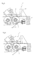
- FIG. 1 shows in greatly simplified form the device 1 (winding machine) for winding a material web 2 to a winding roll 3. Shown is a situation in which the material web 2 is just torn off. A free "flag" 4, which is without tension, forms a remainder of the material web 2, which is otherwise wound on the winding roll 3.
- the winding roll 3 lies in a winding bed 5, which is formed by two support rollers 6, 7. Both support rollers 6, 7 each have a drive, not shown. In operation, the two support rollers 6, 7 are driven in the counterclockwise direction. The resting on the two support rollers 6, 7 winding roll 3 is thereby also set in rotation and pulls the web 2 on it.
- a diameter measuring device 8 continuously or if necessary determines the diameter D of the winding roll 3.
- This diameter measuring device 8 may have different configurations. Preferably, it works without contact, for example with ultrasound or infrared.
- the winding roller 3 forms with the two support rollers 6, 7 each have a Maulageip 9, 10.
- the position of the Auflagenips 9, 10 changes in the course of the winding process. As the diameter D of the winding roll 3 increases, the winding roll 3 moves further out of the winding bed 5. If necessary, you can the Position the Auflagenips 9, 10 or use their distance for the determination of the diameter D of the winding roll 3.
- one end 11 of the material web 2 usually has an indeterminate course. It is extremely unlikely that the crack edge follows a straight line. It is equally unlikely that the end 11 is perpendicular to the direction L (arrow) of the web 2. The resulting by the web tear end 11 is therefore basically not to use for further processing. An operator must therefore take certain measures, which are explained below.
- the operator will clean the winding machine 1 of web residues and cut off the end of the web 2 on the circumference of the winding roll 3 temporarily.
- the end can be separated, for example, in Auflageip 10, because the web 2 is clamped there between the support roller 7 and the winding roller 3.
- the support roller 7 further has a device 12 for temporary detection of Brutrumen.
- the device 12 is a controllable vacuum zone 13, which is integrated in the support roller 7 and which acts on the roller surface 7.1. For reasons of clarity, the device 12 is only hinted at here.
- the operator now separates the material web 2 on the circumference of the winding roll 3.
- she uses a knife 15 or a similar tool.
- this is not just a single outer layer on the Winding roll 3 is severed, but several layers.
- the position P at which the operator guides the knife 15 through the layers it is displayed by an auxiliary device in the embodiment of a laser pointer 16, which is controlled by a control device 17.
- the laser pointer 16 generates an axis-parallel straight line on the circumference of the winding roll 3, specifically where the cut is to be made.
- the voltage applied to the winding roll 3 material web 2 is severed when creating a first tail 18 and the Bahnschwarte 14 (see Figure 2) at the position P, whose distance from the Auflagenip 10 on the roller 7 is the same as the distance one on the roller. 7 arranged device 12 for temporary detection of the introduced material web 2 to Auflageip 10th
- the first tail 18 is fixed to the winding roll 3.
- the fixation can be done for example by gluing the first tail 18 on the winding roll 3.
- FIG. 2 now shows the winding machine 1 when retracting a sheet web 14.
- the control device 17 now rotates the two support rollers 6, 7 in the direction of L (arrow) of the material web 2 by operating the drives on, so that the operator can pull out the Bahnschwarte 14, which is caused by the severing of the outer layers of the winding roll 3.
- the generated web scarf 14 on at least one of attached to a tension spring 20 directly or indirectly applied terminal 19 and thus upon rotation of the winding roller 3 in the direction L (arrow) of the web 2 away.
- This combination of terminal 19 and tension spring 20 is referred to in professional circles as a balancer.
- the removed from the winding machine 1 Bruschwarte 14 can then be eliminated by the operator in a known manner and optionally fed to the stock preparation of a nearby paper machine.
- FIG. 3 shows the winding machine 1 during introduction of the new material web 2.
- the machine width cut in advance machine width 2 is brought over the stationary support roller 7 and detected by the device 12 temporarily.
- the device 12 comes in the upper region of the support roller 7, preferably between a 12 and 1 o'clock position, to a standstill. Thereafter, the web 2 is cut in the direction L (Peil) of the web 2 after the device 12 by means of a cross-cutting device 21 when generating a web start 22.
- FIG. 4 now shows the winding machine 1 when the first tail 18 is applied to the support roller 7.
- the first tail 18 is severed by means of the cross-cutting device 21 when creating a second tail 23 such that the second tail 23 and the web start 22 adjacent to each other.
- the cross-cutting device 21 for generating the second tail 23 is identical in the present embodiment with the cross-cutting device 21 for generating however, they may be different. Subsequently, at least the severed first tail 18 is removed in a known manner.
- the connection can take place in the region of the transverse separating device 21.
- a device 26 known to those skilled in the art is provided for the automatic application of the connecting strip 24 on the two Brutrume 22, 23 when forming a joint 25, a device 26 known to those skilled in the art is provided.
- the connection strip 24 can also be applied manually.
- FIG. 6 shows the winding machine 1 during top-side joining of the second tail 23 and of the web start 22.
- connection point 25 produced in the running direction L (arrow) of the material web 2 is further moved until on the opposite side of the first material strip 2, a second connecting strip 27 can be attached for two-sided connection of the second tail 23 and the web start 22.
- the two connecting strips 24, 27 are applied from one and the same device 26 to the second tail 23 and the web start 22.
- the application of the second connecting strip 27 is carried out at vorzugêtm standstill in the upper region of the winding roll 3, preferably between a 1 and 2 o'clock position.
- the respective transverse and preferably formed as adhesive tape 28 connecting strips 24, 27 is applied to the second tail 23 and the web beginning 22 at rest or rotating support roller.
- the winding machine 1 can be run up to production speed and the material web 2 can be wound continuously onto the winding roller 3.
- the invention enables a fast and secure generation of a connection point in the reeling of a material web.
Landscapes
- Replacement Of Web Rolls (AREA)
Applications Claiming Priority (1)
| Application Number | Priority Date | Filing Date | Title |
|---|---|---|---|
| DE102006046686A DE102006046686A1 (de) | 2006-09-29 | 2006-09-29 | Verfahren zum Erzeugen einer Verbindungsstelle an einer Wickelrolle und Vorrichtung zum Aufwickeln einer Materialbahn zu einer Wickelrolle |
Publications (3)
| Publication Number | Publication Date |
|---|---|
| EP1905714A2 true EP1905714A2 (fr) | 2008-04-02 |
| EP1905714A3 EP1905714A3 (fr) | 2009-05-27 |
| EP1905714B1 EP1905714B1 (fr) | 2011-07-20 |
Family
ID=38875000
Family Applications (1)
| Application Number | Title | Priority Date | Filing Date |
|---|---|---|---|
| EP07117117A Not-in-force EP1905714B1 (fr) | 2006-09-29 | 2007-09-25 | Procédé destiné à la production d'un emplacement de liaison sur un rouleau d'enroulement et dispositif d'enroulement d'une bande de matériau sur un rouleau d'enroulement |
Country Status (3)
| Country | Link |
|---|---|
| EP (1) | EP1905714B1 (fr) |
| AT (1) | ATE517054T1 (fr) |
| DE (1) | DE102006046686A1 (fr) |
Family Cites Families (4)
| Publication number | Priority date | Publication date | Assignee | Title |
|---|---|---|---|---|
| DE2627103A1 (de) * | 1976-06-16 | 1977-12-22 | Bhs Bayerische Berg | Verfahren und vorrichtung zum automatischen erfassen des endes einer bahn oder eines abrisses und verbinden mit dem anfang einer neuen bahn, insbesondere in wellenpappenanlagen |
| US5092533A (en) * | 1990-10-15 | 1992-03-03 | Beloit Corporation | Method for effecting a set change in a winder |
| DE19753870B4 (de) * | 1997-12-05 | 2005-08-25 | Voith Paper Patent Gmbh | Verfahren und Vorrichtung zum Verbinden des Endes einer ersten Materialbahn mit dem Anfang einer zweiten Materialbahn |
| DE19944958C2 (de) * | 1999-09-20 | 2002-02-07 | Voith Paper Patent Gmbh | Leit- oder Kontaktwalzenanordnung zum Handhaben einer Materialbahn, insbesondere in einer Rollenwickelvorrichtung |
-
2006
- 2006-09-29 DE DE102006046686A patent/DE102006046686A1/de not_active Withdrawn
-
2007
- 2007-09-25 EP EP07117117A patent/EP1905714B1/fr not_active Not-in-force
- 2007-09-25 AT AT07117117T patent/ATE517054T1/de active
Also Published As
| Publication number | Publication date |
|---|---|
| EP1905714A3 (fr) | 2009-05-27 |
| DE102006046686A1 (de) | 2008-04-03 |
| EP1905714B1 (fr) | 2011-07-20 |
| ATE517054T1 (de) | 2011-08-15 |
Similar Documents
| Publication | Publication Date | Title |
|---|---|---|
| DE4003504A1 (de) | Verfahren und vorrichtung zum automatischen wechseln einer vollen wickelrolle gegen eine neue wickelhuelse | |
| EP3381303B1 (fr) | Procédé de fabrication de boudins tubulaires à au moins deux couches de l'industrie de transformation du tabac et dispositif de fabrication de boudins tubulaires à au moins deux couches de l'industrie de transformation du tabac | |
| EP2295356B1 (fr) | Procédé et dispositif destinés au remplacement de bobines d'enroulement | |
| DE19519306A1 (de) | Verfahren und Vorrichtung zum automatischen Trennen und Anwickeln einer Papierbahn | |
| DE4336298A1 (de) | Abwickelvorrichtung mit einer Spliceeinrichtung | |
| DE102019102297A1 (de) | Vorrichtung zum Verbinden von Materialbahnen der Tabak verarbeitenden Industrie | |
| EP1389603B1 (fr) | Méthode et dispositif pour le raccordement de bandes de matériau | |
| EP0683122B1 (fr) | Moyen adhésif pour raccorder des bandes de matériau embobinées en rouleaux entraínés | |
| EP0963909B1 (fr) | Procédé et dispositif pour fabriquer un rouleau de matériau en bande emballée circonférenciellement, et un rouleau de matériau en bande | |
| AT507473B1 (de) | Bahnzusammenfügungsanordnung für einen rollenschneider einer faserbahn und verfahren zum zusammenfügen einer alten bahn mit einer neuen bahn in einem rollenschneider | |
| EP1905714B1 (fr) | Procédé destiné à la production d'un emplacement de liaison sur un rouleau d'enroulement et dispositif d'enroulement d'une bande de matériau sur un rouleau d'enroulement | |
| EP1905715B1 (fr) | Procédé destiné à la production d'un emplacement de liaison sur un rouleau d'enroulement et dispositif d'enroulement d'une bande de matériau sur un rouleau d'enroulement | |
| EP1801058B1 (fr) | Dispositif de raccordement et méthode pour le raccordement de bandes de matériau | |
| DE2547699B2 (de) | Verfahren und Vorrichtung zum Einleiten eines Aufwickelvorganges | |
| AT511278A1 (de) | Verfahren in zusammenhang mit einer rollenschneidmaschine für eine faserbahn | |
| EP1140679B1 (fr) | Procede et dispositif pour le raccord de bandes de materiau | |
| EP0930261B1 (fr) | Méthode et dispositif pour enrouler des bandes refendues en rouleaux | |
| EP1733983B1 (fr) | Méthode pour produire un raccordement sur une bobine et dispositif pour enrouler un materiau en bande sur une bobine | |
| CH432200A (de) | Verfahren zum überlappenden Zusammenschweissen von Aluminiumfolien | |
| EP1818298B1 (fr) | Méthode et dispositif pour enrouler des bandes de parties de matériau sur des noyaux, pour former des rouleaux de partie de matériau | |
| DE4431222C2 (de) | Spitzenetikett für fliegenden Rollenwechsel | |
| DE102006042728A1 (de) | Verfahren und Vorrichtung zum Verbinden zweier Materialbahnen | |
| EP1897831A2 (fr) | Procédé destiné au changement de rouleau dans un dispositif d'enroulement de rouleaux et dispositif d'enroulement de rouleaux pour l'enroulement d'une bande de matériau | |
| EP1493699B1 (fr) | Procédé pour alimenter une bande, notamment une bande de papier ou de carton dans un dispositif pour enrouler des bandes et dispositif pour enrouler des bandes | |
| EP3405421B2 (fr) | Dispositif et procédé de changement d'une bobine et de liaison d'une nouvelle bande de matériau à une extrémité d'une ancienne bande de matériau |
Legal Events
| Date | Code | Title | Description |
|---|---|---|---|
| PUAI | Public reference made under article 153(3) epc to a published international application that has entered the european phase |
Free format text: ORIGINAL CODE: 0009012 |
|
| AK | Designated contracting states |
Kind code of ref document: A2 Designated state(s): AT BE BG CH CY CZ DE DK EE ES FI FR GB GR HU IE IS IT LI LT LU LV MC MT NL PL PT RO SE SI SK TR |
|
| AX | Request for extension of the european patent |
Extension state: AL BA HR MK YU |
|
| PUAL | Search report despatched |
Free format text: ORIGINAL CODE: 0009013 |
|
| AK | Designated contracting states |
Kind code of ref document: A3 Designated state(s): AT BE BG CH CY CZ DE DK EE ES FI FR GB GR HU IE IS IT LI LT LU LV MC MT NL PL PT RO SE SI SK TR |
|
| AX | Request for extension of the european patent |
Extension state: AL BA HR MK RS |
|
| RIC1 | Information provided on ipc code assigned before grant |
Ipc: B65H 18/20 20060101AFI20080110BHEP Ipc: B65H 26/02 20060101ALI20090422BHEP |
|
| 17P | Request for examination filed |
Effective date: 20091127 |
|
| AKX | Designation fees paid |
Designated state(s): AT DE FI IT SE |
|
| GRAP | Despatch of communication of intention to grant a patent |
Free format text: ORIGINAL CODE: EPIDOSNIGR1 |
|
| GRAS | Grant fee paid |
Free format text: ORIGINAL CODE: EPIDOSNIGR3 |
|
| GRAA | (expected) grant |
Free format text: ORIGINAL CODE: 0009210 |
|
| AK | Designated contracting states |
Kind code of ref document: B1 Designated state(s): AT DE FI IT SE |
|
| REG | Reference to a national code |
Ref country code: DE Ref legal event code: R096 Ref document number: 502007007710 Country of ref document: DE Effective date: 20110908 |
|
| REG | Reference to a national code |
Ref country code: SE Ref legal event code: TRGR |
|
| PGFP | Annual fee paid to national office [announced via postgrant information from national office to epo] |
Ref country code: SE Payment date: 20110923 Year of fee payment: 5 |
|
| PLBE | No opposition filed within time limit |
Free format text: ORIGINAL CODE: 0009261 |
|
| STAA | Information on the status of an ep patent application or granted ep patent |
Free format text: STATUS: NO OPPOSITION FILED WITHIN TIME LIMIT |
|
| 26N | No opposition filed |
Effective date: 20120423 |
|
| REG | Reference to a national code |
Ref country code: DE Ref legal event code: R097 Ref document number: 502007007710 Country of ref document: DE Effective date: 20120423 |
|
| PG25 | Lapsed in a contracting state [announced via postgrant information from national office to epo] |
Ref country code: SE Free format text: LAPSE BECAUSE OF NON-PAYMENT OF DUE FEES Effective date: 20120926 |
|
| REG | Reference to a national code |
Ref country code: SE Ref legal event code: EUG |
|
| PGFP | Annual fee paid to national office [announced via postgrant information from national office to epo] |
Ref country code: AT Payment date: 20130911 Year of fee payment: 7 Ref country code: DE Payment date: 20130919 Year of fee payment: 7 Ref country code: FI Payment date: 20130911 Year of fee payment: 7 |
|
| PGFP | Annual fee paid to national office [announced via postgrant information from national office to epo] |
Ref country code: IT Payment date: 20130930 Year of fee payment: 7 |
|
| REG | Reference to a national code |
Ref country code: DE Ref legal event code: R119 Ref document number: 502007007710 Country of ref document: DE |
|
| PG25 | Lapsed in a contracting state [announced via postgrant information from national office to epo] |
Ref country code: FI Free format text: LAPSE BECAUSE OF NON-PAYMENT OF DUE FEES Effective date: 20140925 |
|
| REG | Reference to a national code |
Ref country code: AT Ref legal event code: MM01 Ref document number: 517054 Country of ref document: AT Kind code of ref document: T Effective date: 20140925 |
|
| REG | Reference to a national code |
Ref country code: DE Ref legal event code: R119 Ref document number: 502007007710 Country of ref document: DE Effective date: 20150401 |
|
| PG25 | Lapsed in a contracting state [announced via postgrant information from national office to epo] |
Ref country code: DE Free format text: LAPSE BECAUSE OF NON-PAYMENT OF DUE FEES Effective date: 20150401 |
|
| PG25 | Lapsed in a contracting state [announced via postgrant information from national office to epo] |
Ref country code: AT Free format text: LAPSE BECAUSE OF NON-PAYMENT OF DUE FEES Effective date: 20140925 Ref country code: IT Free format text: LAPSE BECAUSE OF NON-PAYMENT OF DUE FEES Effective date: 20140925 |