EP1905942B1 - Palier de position de travail - Google Patents
Palier de position de travail Download PDFInfo
- Publication number
- EP1905942B1 EP1905942B1 EP20060020227 EP06020227A EP1905942B1 EP 1905942 B1 EP1905942 B1 EP 1905942B1 EP 20060020227 EP20060020227 EP 20060020227 EP 06020227 A EP06020227 A EP 06020227A EP 1905942 B1 EP1905942 B1 EP 1905942B1
- Authority
- EP
- European Patent Office
- Prior art keywords
- stop
- segment
- working position
- position bearing
- bearing according
- Prior art date
- Legal status (The legal status is an assumption and is not a legal conclusion. Google has not performed a legal analysis and makes no representation as to the accuracy of the status listed.)
- Not-in-force
Links
Images


Classifications
-
- E—FIXED CONSTRUCTIONS
- E06—DOORS, WINDOWS, SHUTTERS, OR ROLLER BLINDS IN GENERAL; LADDERS
- E06B—FIXED OR MOVABLE CLOSURES FOR OPENINGS IN BUILDINGS, VEHICLES, FENCES OR LIKE ENCLOSURES IN GENERAL, e.g. DOORS, WINDOWS, BLINDS, GATES
- E06B9/00—Screening or protective devices for wall or similar openings, with or without operating or securing mechanisms; Closures of similar construction
- E06B9/24—Screens or other constructions affording protection against light, especially against sunshine; Similar screens for privacy or appearance; Slat blinds
- E06B9/26—Lamellar or like blinds, e.g. venetian blinds
- E06B9/28—Lamellar or like blinds, e.g. venetian blinds with horizontal lamellae, e.g. non-liftable
- E06B9/30—Lamellar or like blinds, e.g. venetian blinds with horizontal lamellae, e.g. non-liftable liftable
- E06B9/303—Lamellar or like blinds, e.g. venetian blinds with horizontal lamellae, e.g. non-liftable liftable with ladder-tape
- E06B9/308—Lamellar or like blinds, e.g. venetian blinds with horizontal lamellae, e.g. non-liftable liftable with ladder-tape with coaxial tilting bar and raising shaft
Definitions
- the advantage of the working position bearing according to the invention is that a more favorable flow of forces is possible by the separation of the segment stop of the lever due to better leverage.
- the second axis namely the lateral offset in the course of forces over short lever arms can be transmitted from the lever designed as a rocker lever on the segment stop.
- no significant twisting of the lever occurs when the working position is triggered, since it is stressed only on bending and not additionally on torsion.
- the switching rocker is provided for cooperation with the driver with a rounded cam. Due to the rounded cam, the frictional resistance when interacting with the driver is reduced to a minimum.
- the abutment surface of the segment stop is formed by two stop faces, between which a recess is provided, so that a fixed to the wedge segment coupling band is not affected by the stop surface, d. H. can freely move freely in the area of the recess.
- the segment stop is provided with a support surface, which in the stop position of the segment stop on at least one of the outer peripheral surfaces of the inclined flanks of the turning roller rests.
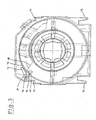
- a work positioning bearing 10 with a housing 12, a shaft 14, a winding roller 16 and a turning roller with a wedge segment 18 shown wherein like parts have been provided with the same reference numerals and the winding roll and the turning roll are in turn formed as a part.
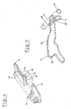
- the segment stop 24 is held pivotably about a second axis 34 arranged at a distance from the first axis 28.
- the lever 26 is formed as a switching rocker, which is switchable by means of the actuator 32. By the switching rocker 26 of the segment stop 24 is movable from a stop position to a release position in which it is outside the path of movement of the wedge segment 18.
- the rocker switch 26 has at its end opposite the pivotable bearing a cam 38 which is connected to the segment stop 24 cooperates and the surface 40 is rounded in the direction of pivotal movement of the rocker switch 26.
- a driver 42 is provided on a hollow shaft 41, which cooperates with the cam 38 of the switching rocker 26.
- the segment stop 24 is also formed with a stop surface 44 for the wedge segment 18, whose surface is provided in the direction of pivotal movement of the segment stop 24 with a convex curve 46.
- the stop surface 44 is connected to the hollow shaft 41.
- the work position bearing has in addition to the winding roller 16 via an associated with this turning roller 48, as in Fig. 2 is shown in a longitudinal section.
- the turning roller 48 and the winding roller 16 are arranged axially spaced on the shaft 14.
- the turning roller 48 has sloping flanks 50, between which the wedge segment 18 is received with a coupling belt can be fixed thereto so that a frictional entrainment of the wedge segment 18 is made possible by the shaft 14.
- the coupling band not shown, extends in the U-shaped wedge segment 18th
- Fig. 3 a section through the plane of the turning roller 48 is shown.
- the segment stop 24 is provided with a support plate 72 located in the in Fig. 1 shown stop position on outer peripheral surfaces 74 of the inclined flanks 50 of the turning roller 48 is supported.
- the stop surface 44 of the segment stop 24 is formed by two stop faces 81, between which a recess 82 is provided. Through the recess 82, the fixable on the wedge segment 18 coupling band can run smoothly.
Landscapes
- Engineering & Computer Science (AREA)
- Structural Engineering (AREA)
- Architecture (AREA)
- Civil Engineering (AREA)
- Operating, Guiding And Securing Of Roll- Type Closing Members (AREA)
- Blinds (AREA)
Claims (12)
- Palier de position de travail (10) pour un store à lamelles comprenant un rideau à lamelles, comprenant un caisson (12) et un arbre (14) sur lequel au moins un rouleau d'enroulement (16) pour recevoir une bande de relevage et au moins un rouleau d'orientation (48) sont montés, sachant que le rouleau d'orientation (48) possède des flancs inclinés entre lesquels un segment conique (18) avec une bande de couplage pouvant être fixée dessus, est reçu de façon à permettre un entraînement avec engagement par friction du segment conique (18) par l'arbre (14), et des première et seconde butées de caisson (20, 22) sont prévues qui délimitent l'entraînement dans une première, respectivement, une seconde position angulaire, de même qu'une butée de segment (24) maintenue en pouvant pivoter est prévue, laquelle peut passer d'une position de butée dans laquelle elle est rentrée dans la trajectoire du segment conique (18), à une position libérée dans laquelle elle se trouve en-dehors de la trajectoire du segment conique (18), à l'aide d'un levier (26) qui est positionné pivotant sur un premier axe (28) et qui peut être déclenché par un élément de réglage (32) en fonction de l'état d'enroulement de la bande de relevage à enrouler, caractérisé en ce que la butée de segment (24) est maintenue en pouvant pivoter sur un second axe (34) disposé à distance du premier axe (28) et peut être déplacée de la position de butée à la position libérée par le levier (26) conçu séparément de la butée de segment (24) en tant que bascule.
- Palier de position de travail selon la revendication 1, caractérisé en ce qu'un entraîneur (42) est relié fixe en rotation à la butée de segment (24), lequel coopère avec la bascule.
- Palier de position de travail selon la revendication 2, caractérisé en ce que la bascule est dotée d'une came arrondie (38) pour coopérer avec l'entraîneur (42).
- Palier de position de travail selon l'une des revendications 1 à 3, caractérisé en ce que la butée de segment (24) est formée avec une surface de butée (44) pour le segment conique (18), dont la face supérieure est arrondie de façon convexe.
- Palier de position de travail selon la revendication 4, caractérisé en ce que la surface de butée (44) de la butée de segment (24) est formée par deux surfaces partielles de butée (81) entre lesquelles un évidement (82) est prévu.
- Palier de position de travail selon l'une des revendications précédentes, caractérisé en ce que la butée de segment (24), dans la position de butée, peut être appuyée par un plateau d'appui (72) sur au moins une des surfaces du pourtour extérieur (74) des flancs inclinés (50) du rouleau d'orientation (48).
- Palier de position de travail selon l'une des revendications précédentes, caractérisé en ce que la bascule (36) est dotée d'un levier d'arrêt (76) en tant qu'appui de montage.
- Palier de position de travail selon l'une des revendications précédentes, caractérisé en ce qu'il peut être intégré dans un rail supérieur ouvert vers le bas.
- Palier de position de travail selon l'une des revendications précédentes, caractérisé en ce qu'il est essentiellement fabriqué intégralement en plastique.
- Palier de position de travail pour un store à lamelles comprenant un rideau à lamelles selon la revendication 1, comprenant un caisson (12) et un arbre (14) sur lequel au moins un rouleau d'enroulement (16) est monté, qui est doté d'au moins une rainure (52) périphérique pour recevoir une bande de relevage qui est délimitée par des parois latérales (54, 56), caractérisé en ce que le rouleau d'enroulement (16) présente au moins deux rainures (52, 61) de largeur différente pour la réception au choix de bandes de relevage de différente largeur.
- Palier de position de travail selon la revendication 9, caractérisé en ce qu'une butée de segment (24) pouvant être couplée est prévue, qui peut être actionnée par un levier (26) qui peut être déclenché par un élément de réglage (32) en fonction de l'état d'enroulement de la bande de relevage à enrouler, sachant que le levier (16) et disposé entre deux rainures (52,61) du rouleau d'enroulement (16) et que le membre de réglage (32) s'étend dans les deux rainures (52, 61).
- Palier de position de travail selon l'une des revendications précédentes, caractérisé en ce que le rouleau d'enroulement (16) et le rouleau d'orientation (18) sont conçus en tant qu'une partie.
Priority Applications (1)
| Application Number | Priority Date | Filing Date | Title |
|---|---|---|---|
| EP20060020227 EP1905942B1 (fr) | 2006-09-27 | 2006-09-27 | Palier de position de travail |
Applications Claiming Priority (1)
| Application Number | Priority Date | Filing Date | Title |
|---|---|---|---|
| EP20060020227 EP1905942B1 (fr) | 2006-09-27 | 2006-09-27 | Palier de position de travail |
Publications (2)
| Publication Number | Publication Date |
|---|---|
| EP1905942A1 EP1905942A1 (fr) | 2008-04-02 |
| EP1905942B1 true EP1905942B1 (fr) | 2014-07-16 |
Family
ID=37891938
Family Applications (1)
| Application Number | Title | Priority Date | Filing Date |
|---|---|---|---|
| EP20060020227 Not-in-force EP1905942B1 (fr) | 2006-09-27 | 2006-09-27 | Palier de position de travail |
Country Status (1)
| Country | Link |
|---|---|
| EP (1) | EP1905942B1 (fr) |
Families Citing this family (1)
| Publication number | Priority date | Publication date | Assignee | Title |
|---|---|---|---|---|
| CH702509A1 (de) * | 2010-01-11 | 2011-07-15 | Griesser Holding Ag | Stellvorrichtung und Verfahren zum Aktivieren und Deaktivieren der Arbeitsstellung bei einer Rafflamellenstore. |
Family Cites Families (3)
| Publication number | Priority date | Publication date | Assignee | Title |
|---|---|---|---|---|
| DE3625365A1 (de) * | 1986-07-26 | 1988-02-04 | Warema Renkhoff Gmbh & Co Kg | Wendevorrichtung fuer eine raffbare lamellenjalousie mit drei lamellenstellungen |
| DE3718513C2 (de) * | 1987-06-03 | 1994-04-14 | Warema Renkhoff Gmbh & Co Kg | Wendevorrichtung für eine raffbare Lamellenjalousie |
| DE10236869A1 (de) * | 2002-08-12 | 2004-02-26 | Warema Kunststofftechnik Und Maschinenbau Gmbh | Raffstore mit Wendelager |
-
2006
- 2006-09-27 EP EP20060020227 patent/EP1905942B1/fr not_active Not-in-force
Also Published As
| Publication number | Publication date |
|---|---|
| EP1905942A1 (fr) | 2008-04-02 |
Similar Documents
| Publication | Publication Date | Title |
|---|---|---|
| DE60215941T2 (de) | Bremsvorrichtung für rollos und dergleichen | |
| DE60114995T2 (de) | Motorisierter rolladen mit automatischen blockiervorrichtungen | |
| WO1994002705A1 (fr) | Volet roulant du type jalousie | |
| CH653090A5 (de) | Rafflamellenstore. | |
| DE69723655T2 (de) | Fallsicherungsvorrichtung für vertikal aufrollbare Verschlusseinrichtungen | |
| EP0127749A2 (fr) | Dispositif de sécurité contre le levage et store à lamelles comportant un tel dispositif | |
| DE69007992T2 (de) | Auf-/Abtriebs- und Rotationsvorrichtung für die Lamellen von horizontalen Stores. | |
| CH653093A5 (de) | Rafflamellenstore. | |
| CH650311A5 (de) | Rafflamellenstore. | |
| EP0887508B1 (fr) | Store vénitien avec rail supérieur déplaçable | |
| DE3313833A1 (de) | Wendevorrichtung einer lamellenjalousie | |
| EP1905942B1 (fr) | Palier de position de travail | |
| EP0716203B1 (fr) | Entraínement à câble, en particulier pour une porte de garage | |
| EP0684361A1 (fr) | Dispositif de levage et de pivotement pour stores à lamelles | |
| DE60017006T2 (de) | Antrieb für eine Jalousie | |
| DE69720627T2 (de) | Arretierung für Rolladen, mit einer frei drehbaren Wickelwelle | |
| EP2520698A1 (fr) | Dispositif de formation de la foule pour un métier à tisser | |
| CH696275A5 (de) | Raffstore mit Wendelager. | |
| DE19534970C2 (de) | Wendevorrichtung für eine raffbare Lamellenjalousie | |
| DE69723652T2 (de) | Antriebsvorrichtung für Rolladen oder dergleichen | |
| DE102012001531B4 (de) | Aufzugs-/Wendelager mit schaltbarer Zwischenstellung | |
| DE3037733A1 (de) | Rafflamellenstore | |
| DE8900256U1 (de) | Aufzugsvorrichtung eines freihängenden Vorhanges | |
| EP2343431A2 (fr) | Dispositif de réglage et procédé d'activation et de désactivation de la position de fonctionnement d'un store vénitien | |
| DE19928409A1 (de) | Steuerungs- und Aufhängungssystem für eine Abdeckung für bauliche Öffnungen |
Legal Events
| Date | Code | Title | Description |
|---|---|---|---|
| PUAI | Public reference made under article 153(3) epc to a published international application that has entered the european phase |
Free format text: ORIGINAL CODE: 0009012 |
|
| AK | Designated contracting states |
Kind code of ref document: A1 Designated state(s): AT BE BG CH CY CZ DE DK EE ES FI FR GB GR HU IE IS IT LI LT LU LV MC NL PL PT RO SE SI SK TR |
|
| AX | Request for extension of the european patent |
Extension state: AL BA HR MK YU |
|
| 17P | Request for examination filed |
Effective date: 20080514 |
|
| AKX | Designation fees paid |
Designated state(s): AT CH DE LI |
|
| GRAP | Despatch of communication of intention to grant a patent |
Free format text: ORIGINAL CODE: EPIDOSNIGR1 |
|
| INTG | Intention to grant announced |
Effective date: 20140219 |
|
| GRAS | Grant fee paid |
Free format text: ORIGINAL CODE: EPIDOSNIGR3 |
|
| GRAA | (expected) grant |
Free format text: ORIGINAL CODE: 0009210 |
|
| AK | Designated contracting states |
Kind code of ref document: B1 Designated state(s): AT CH DE LI |
|
| REG | Reference to a national code |
Ref country code: CH Ref legal event code: EP |
|
| REG | Reference to a national code |
Ref country code: AT Ref legal event code: REF Ref document number: 677787 Country of ref document: AT Kind code of ref document: T Effective date: 20140815 |
|
| REG | Reference to a national code |
Ref country code: DE Ref legal event code: R096 Ref document number: 502006013852 Country of ref document: DE Effective date: 20140821 |
|
| REG | Reference to a national code |
Ref country code: CH Ref legal event code: NV Representative=s name: ISLER AND PEDRAZZINI AG, CH |
|
| REG | Reference to a national code |
Ref country code: DE Ref legal event code: R097 Ref document number: 502006013852 Country of ref document: DE |
|
| PLBE | No opposition filed within time limit |
Free format text: ORIGINAL CODE: 0009261 |
|
| STAA | Information on the status of an ep patent application or granted ep patent |
Free format text: STATUS: NO OPPOSITION FILED WITHIN TIME LIMIT |
|
| 26N | No opposition filed |
Effective date: 20150417 |
|
| PGFP | Annual fee paid to national office [announced via postgrant information from national office to epo] |
Ref country code: CH Payment date: 20150916 Year of fee payment: 10 |
|
| PGFP | Annual fee paid to national office [announced via postgrant information from national office to epo] |
Ref country code: AT Payment date: 20150903 Year of fee payment: 10 |
|
| REG | Reference to a national code |
Ref country code: DE Ref legal event code: R082 Ref document number: 502006013852 Country of ref document: DE Representative=s name: PATENTANWAELTE OLBRICHT, BUCHHOLD, KEULERTZ PA, DE |
|
| REG | Reference to a national code |
Ref country code: CH Ref legal event code: PL |
|
| REG | Reference to a national code |
Ref country code: AT Ref legal event code: MM01 Ref document number: 677787 Country of ref document: AT Kind code of ref document: T Effective date: 20160927 |
|
| PG25 | Lapsed in a contracting state [announced via postgrant information from national office to epo] |
Ref country code: LI Free format text: LAPSE BECAUSE OF NON-PAYMENT OF DUE FEES Effective date: 20160930 Ref country code: CH Free format text: LAPSE BECAUSE OF NON-PAYMENT OF DUE FEES Effective date: 20160930 |
|
| PG25 | Lapsed in a contracting state [announced via postgrant information from national office to epo] |
Ref country code: AT Free format text: LAPSE BECAUSE OF NON-PAYMENT OF DUE FEES Effective date: 20160927 |
|
| PGFP | Annual fee paid to national office [announced via postgrant information from national office to epo] |
Ref country code: DE Payment date: 20170930 Year of fee payment: 12 |
|
| REG | Reference to a national code |
Ref country code: DE Ref legal event code: R119 Ref document number: 502006013852 Country of ref document: DE |
|
| PG25 | Lapsed in a contracting state [announced via postgrant information from national office to epo] |
Ref country code: DE Free format text: LAPSE BECAUSE OF NON-PAYMENT OF DUE FEES Effective date: 20190402 |