EP1906514A2 - Linearmotor und Werkzeugmaschine mit darauf montiertem Linearmotor - Google Patents
Linearmotor und Werkzeugmaschine mit darauf montiertem Linearmotor Download PDFInfo
- Publication number
- EP1906514A2 EP1906514A2 EP07017229A EP07017229A EP1906514A2 EP 1906514 A2 EP1906514 A2 EP 1906514A2 EP 07017229 A EP07017229 A EP 07017229A EP 07017229 A EP07017229 A EP 07017229A EP 1906514 A2 EP1906514 A2 EP 1906514A2
- Authority
- EP
- European Patent Office
- Prior art keywords
- linear motor
- magnet member
- axial direction
- coil
- coil member
- Prior art date
- Legal status (The legal status is an assumption and is not a legal conclusion. Google has not performed a legal analysis and makes no representation as to the accuracy of the status listed.)
- Granted
Links
- 230000005291 magnetic effect Effects 0.000 claims abstract description 46
- 238000004080 punching Methods 0.000 claims abstract description 5
- 238000012545 processing Methods 0.000 claims description 44
- 239000000463 material Substances 0.000 claims description 3
- XEEYBQQBJWHFJM-UHFFFAOYSA-N Iron Chemical group [Fe] XEEYBQQBJWHFJM-UHFFFAOYSA-N 0.000 abstract description 3
- 239000000126 substance Substances 0.000 description 20
- 230000002093 peripheral effect Effects 0.000 description 9
- 230000007246 mechanism Effects 0.000 description 7
- 230000015556 catabolic process Effects 0.000 description 6
- 238000006731 degradation reaction Methods 0.000 description 6
- 238000001514 detection method Methods 0.000 description 6
- 238000001816 cooling Methods 0.000 description 4
- 238000010586 diagram Methods 0.000 description 2
- 238000004891 communication Methods 0.000 description 1
- 239000000110 cooling liquid Substances 0.000 description 1
- 230000003028 elevating effect Effects 0.000 description 1
- 230000005294 ferromagnetic effect Effects 0.000 description 1
- 230000004907 flux Effects 0.000 description 1
- 230000010354 integration Effects 0.000 description 1
- 229910052742 iron Inorganic materials 0.000 description 1
- 238000003754 machining Methods 0.000 description 1
- 238000000034 method Methods 0.000 description 1
- 238000012986 modification Methods 0.000 description 1
- 230000004048 modification Effects 0.000 description 1
- 238000012544 monitoring process Methods 0.000 description 1
- 230000008569 process Effects 0.000 description 1
- 230000009467 reduction Effects 0.000 description 1
Images


Classifications
-
- H—ELECTRICITY
- H02—GENERATION; CONVERSION OR DISTRIBUTION OF ELECTRIC POWER
- H02K—DYNAMO-ELECTRIC MACHINES
- H02K41/00—Propulsion systems in which a rigid body is moved along a path due to dynamo-electric interaction between the body and a magnetic field travelling along the path
- H02K41/02—Linear motors; Sectional motors
-
- B—PERFORMING OPERATIONS; TRANSPORTING
- B30—PRESSES
- B30B—PRESSES IN GENERAL
- B30B1/00—Presses, using a press ram, characterised by the features of the drive therefor, pressure being transmitted directly, or through simple thrust or tension members only, to the press ram or platen
- B30B1/42—Presses, using a press ram, characterised by the features of the drive therefor, pressure being transmitted directly, or through simple thrust or tension members only, to the press ram or platen by magnetic means, e.g. electromagnetic
-
- H—ELECTRICITY
- H02—GENERATION; CONVERSION OR DISTRIBUTION OF ELECTRIC POWER
- H02K—DYNAMO-ELECTRIC MACHINES
- H02K11/00—Structural association of dynamo-electric machines with electric components or with devices for shielding, monitoring or protection
- H02K11/20—Structural association of dynamo-electric machines with electric components or with devices for shielding, monitoring or protection for measuring, monitoring, testing, protecting or switching
- H02K11/21—Devices for sensing speed or position, or actuated thereby
-
- H—ELECTRICITY
- H02—GENERATION; CONVERSION OR DISTRIBUTION OF ELECTRIC POWER
- H02K—DYNAMO-ELECTRIC MACHINES
- H02K41/00—Propulsion systems in which a rigid body is moved along a path due to dynamo-electric interaction between the body and a magnetic field travelling along the path
- H02K41/02—Linear motors; Sectional motors
- H02K41/03—Synchronous motors; Motors moving step by step; Reluctance motors
- H02K41/031—Synchronous motors; Motors moving step by step; Reluctance motors of the permanent magnet type
-
- H—ELECTRICITY
- H02—GENERATION; CONVERSION OR DISTRIBUTION OF ELECTRIC POWER
- H02K—DYNAMO-ELECTRIC MACHINES
- H02K2213/00—Specific aspects, not otherwise provided for and not covered by codes H02K2201/00 - H02K2211/00
- H02K2213/03—Machines characterised by numerical values, ranges, mathematical expressions or similar information
-
- H—ELECTRICITY
- H02—GENERATION; CONVERSION OR DISTRIBUTION OF ELECTRIC POWER
- H02K—DYNAMO-ELECTRIC MACHINES
- H02K7/00—Arrangements for handling mechanical energy structurally associated with dynamo-electric machines, e.g. structural association with mechanical driving motors or auxiliary dynamo-electric machines
- H02K7/10—Structural association with clutches, brakes, gears, pulleys or mechanical starters
- H02K7/106—Structural association with clutches, brakes, gears, pulleys or mechanical starters with dynamo-electric brakes
-
- H—ELECTRICITY
- H02—GENERATION; CONVERSION OR DISTRIBUTION OF ELECTRIC POWER
- H02K—DYNAMO-ELECTRIC MACHINES
- H02K7/00—Arrangements for handling mechanical energy structurally associated with dynamo-electric machines, e.g. structural association with mechanical driving motors or auxiliary dynamo-electric machines
- H02K7/10—Structural association with clutches, brakes, gears, pulleys or mechanical starters
- H02K7/118—Structural association with clutches, brakes, gears, pulleys or mechanical starters with starting devices
- H02K7/1185—Structural association with clutches, brakes, gears, pulleys or mechanical starters with starting devices with a mechanical one-way direction control, i.e. with means for reversing the direction of rotation of the rotor
-
- Y—GENERAL TAGGING OF NEW TECHNOLOGICAL DEVELOPMENTS; GENERAL TAGGING OF CROSS-SECTIONAL TECHNOLOGIES SPANNING OVER SEVERAL SECTIONS OF THE IPC; TECHNICAL SUBJECTS COVERED BY FORMER USPC CROSS-REFERENCE ART COLLECTIONS [XRACs] AND DIGESTS
- Y10—TECHNICAL SUBJECTS COVERED BY FORMER USPC
- Y10T—TECHNICAL SUBJECTS COVERED BY FORMER US CLASSIFICATION
- Y10T83/00—Cutting
- Y10T83/929—Tool or tool with support
- Y10T83/9457—Joint or connection
- Y10T83/9473—For rectilinearly reciprocating tool
- Y10T83/9476—Tool is single element with continuous cutting edge [e.g., punch, etc.]
Definitions
- the present invention relates to a linear motor device and a machine tool such as a press machine in which the linear motor device is mounted.
- a conventionally proposed linear motor comprises a magnet member composed of round-shaft-like permanent magnets having alternately arranged respective N poles and S poles, and a coil member having a plurality of coils arranged in an axial direction so as to surround the periphery of the magnet member (for example, the Unexamined Japanese Patent Application Publication (Tokkai-Hei) No. 10-313566 ).
- the linear motor disclosed in the Unexamined Japanese Patent Application Publication (Tokkai-Hei) No.10-313566 is used, for example, in 0A equipment or the like in place of a combination of a rotary motor and a ball screw.
- a machine tool such as a press machine which makes direct-acting motion also results in a simple configuration and enhanced controllability.
- the linear motor is performing a direct-acting operation, where a magnetic substance is present around the outer periphery of a magnet member in a route of the linear motor, an attractive force varies at a period when the magnet member passes through each magnetic pole of the magnet member. This varies a resulting thrust.
- the magnetic substance may be provided, for example, in order to prevent the magnet member from falling down.
- the linear motor is used as a driving source for a machine tool such as a press machine
- the variation in attractive force varies the speed of the contact between a workpiece and a tool.
- the variation in contact speed is reflected in the processing quality such as a press cut surface or a machining processing surface. Thus, the processing quality is degraded.
- a linear motor device in accordance with the present invention comprises a linear motor and a control section that controls the linear motor.
- the linear motor comprises a magnet member composed of permanent magnets having respective N poles and S poles alternately arranged in an axial direction, and a coil member which is located orthogonally to the axial direction with respect to the magnet member and through which the magnet member is movable in the axial direction relative to the coil member.
- the control section controls current conducted through the coil member so that a moving one of the magnet member and the coil member reciprocates within a part of a range between magnetic poles in the magnet member.
- the term "a part” as used herein means “not all” and may refer to, for example, most of the range between the magnetic poles in the magnet member.
- control section controls the current conducted through the coil member so that the moving one of the magnet member and the coil member reciprocates within the part of the range between the magnetic poles in the magnet member. Consequently, the linear motor reciprocates within the range in which the attractive force does not vary significantly. This reduces a variation in thrust caused by a variation in attractive force.
- a machine tool in accordance with the present invention comprises processing means for processing a workpiece and a drive means for reciprocating the processing means.
- the drive means comprises a linear motor and a control section that controls the linear motor.
- the linear motor comprises a magnet member composed of permanent magnets having respective N poles and S poles alternately arranged in an axial direction, and a coil member which is located orthogonally to the axial direction with respect to the magnet member and through which the magnet member is movable in the axial direction relative to the coil member.
- the control section controls current conducted through the coil member so that a moving one of the magnet member and the coil member which is combined to the processing means reciprocates within a part of a range between the magnetic poles in the magnet member.
- This configuration uses the linear motor as drive means for reciprocating the processing means.
- the use of the linear motor eliminates the need for a mechanism that converts rotation into a reciprocating operation, simplifying the configuration. Further, the control section performs control such that the linear motor performs a reciprocating operation within the range in which the attractive force does not vary significantly. This reduces a variation in thrust caused by a variation in attractive force. This in turn makes it possible to avoid the degradation of processing quality associated with the variation in attractive force, allowing the processing quality to be improved.
- the machine tool may be a press machine. That is, a press machine in accordance with the present invention comprises a press processing means for executing processing such as punching or forming on a plate material and drive means for driving the press processing means.
- the drive means comprises a linear motor and a control section that controls the linear motor.
- the linear motor comprises a magnet member composed of permanent magnets having respective N poles and S poles alternately arranged in an axial direction, and a coil member which is located orthogonally to the axial direction with respect to the magnet member and through which the magnet member is movable in the axial direction relative to the coil member.
- the control section controls current conducted through the coil member so that a moving one of the magnet member and the coil member which is combined to the press processing means reciprocates within a part of a range between the magnetic poles in the magnet member.
- This configuration uses the linear motor as a drive means for reciprocating the press processing means.
- the use of the linear motor eliminates the need for a mechanism that converts rotation into a reciprocating operation, simplifying the configuration.
- the control section performs control such that the linear motor performs a reciprocating operation within the range in which the attractive force does not vary significantly. This reduces a variation in thrust caused by a variation in attractive force. This in turn makes it possible to avoid the degradation of the processing quality associated with the variation in attractive force, allowing the processing quality to be improved.
- the linear motor device in accordance with the present invention comprises the linear motor and the control section that controls the linear motor.
- the linear motor comprises the magnet member composed of the permanent magnets having the respective N poles and S poles alternately arranged in the axial direction, and the coil member which is located orthogonally to the axial direction with respect to the magnet member and through which the magnet member is movable in the axial direction relative to the coil member.
- the control section controls the current conducted through the coil member so that the moving one of the magnet member and the coil member reciprocates within the part of the range between the magnetic poles in the magnet member. This reduces the variation in thrust caused by the variation in attractive force.
- the machine tool in accordance with the present invention comprises the processing means for processing the workpiece and the drive means for reciprocating the processing means.
- the drive means comprises the linear motor and the control section that controls the linear motor.
- the linear motor comprises the magnet member composed of the permanent magnets having the respective N poles and S poles alternately arranged in the axial direction, and the coil member which is located orthogonally to the axial direction with respect to the magnet member and through which the magnet member is movable in the axial direction relative to the coil member.
- the control section controls the current conducted through the coil member so that the moving one of the magnet member and the coil member which is combined to the processing means reciprocates within the part of the range between the magnetic poles in the magnet member. This configuration can reduce the degradation of the processing quality caused by the variation in attractive force, while using the linear motor as a driving source for simplification.
- the press machine in accordance with the present invention comprises the press processing means for executing processing such as punching or forming on the plate material and the drive means for driving the press processing means.
- the drive means comprises the linear motor and the control section that controls the linear motor.
- the linear motor comprises the magnet member composed of the permanent magnets having the respective N poles and S poles alternately arranged in the axial direction, and the coil member which is located orthogonally to the axial direction with respect to the magnet member and through which the magnet member is movable in the axial direction relative to the coil member.
- the control section controls the current conducted through the coil member so that the moving one of the magnet member and the coil member which is combined to the press processing means reciprocates within the part of the range between the magnetic poles in the magnet member. This configuration can reduce the degradation of the processing quality caused by the variation in attractive force.
- the present linear motor device comprises a linear motor 1 and a control section 30 that controls the linear motor 1.
- the linear motor 1 comprises a magnet member 2 composed of permanent magnets having respective N poles and S poles alternately arranged in an axial direction, and a coil member 3 which is located orthogonally to the axial direction with respect to the magnet member 2 and through which the magnet member 2 is movable in the axial direction relative to the coil member 3.
- Either the magnet member 2 or the coil member 3 may be a moving side.
- the magnet member 2 is a moving-side member
- the coil member 3 is a fixed-side member.
- the magnet member 2 is a round bar-like member.
- a magnetic flux (a) is generated between the adjacent magnetic poles N and S as shown by arrow a in Figure 1.
- the coil member 3 is configured as a coil unit having a plurality of cylindrical coils 6 arranged in the axial direction so as to surround the periphery of the magnet member 2. The coils 6 are connected together in parallel.
- the coil member 3 has a magnetic substance 13 provided, for example, at one end thereof to allow the magnet member 2 to exert a magnetic attractive force.
- the magnetic substance 13 is provided, for example, in order to inhibit the magnet member 2 from falling down or hold the position of the magnet member 2 when a power supply to the coil member 3 is turned off.
- the control section 30 controls current conducted through the coils 6 of the coil member 3 so that the magnet member 2 reciprocates within a use range L corresponding to a part of a pitch (p) between the magnetic poles N and S in the magnet member 2.
- the control section 30 is composed of a power control section 32 that outputs a driving current exciting each of the coils 6 of the coil member 3, a control signal generating section 31 that outputs control signals allowing the power control section 32 to switch between a state in which the driving current is output and a state in which the driving current is stopped, and to switch a current flowing direction, and a data converting circuit 33 which converts a signal from a position detector 34 detecting the forward or backward position of the magnet member 2 and which then inputs the resulting signal to the control signal generating section 31.
- the power control section 32 outputs a three-phase alternating current or the like as the driving current.
- the power control section 32 comprises an inverter circuit that converts a three-phase commercial alternating current power supply into an output of a predetermined frequency. With the linear motor 1, the power control section 32 maintains the output of the driving current to excite the coils 6 to continuously move the magnet member 2 in a given direction.
- the position detector 34 is composed of a linear scale 35 extending in the axial direction of the magnet member 2 and a detection head 36 that reads the linear scale 35.
- the linear scale 35 is mounted to the magnet member 2 via a scale mounting part 37.
- the detection head 35 is mounted, via a detection head mounting part 38, to a member to which the coil member 3 is fixed or to the coil member 3.
- the detection head mounting part 38 is mounted to a ram guide 50 that guides a ram 49 of a press machine shown below in Figure 5.
- the data converting circuit 33 is a circuit that converts an output from the detection head 36 of the position detector 34 into a position signal that can be handled by the control signal generating section 31. For example, where the position detector 34 is of an incremental type that outputs a pulse equivalent to a travel distance, from the detection head 36, the data converting circuit 33 converts the pulse into position data of a digital value.
- the data converting circuit 33 is unnecessary.
- a predetermined use range L is set which corresponds to a part of the pitch (p) between the magnetic poles N and S in the magnet member 2.
- the control signal generating section 31 has a function of monitoring the position of the magnet member 2 obtained from the position detector 34 and performing control such that the magnet member 2 does not move out of the predetermined moving range during reciprocating motion. For example, when the position of the magnet member 2 reaches one end of the predetermined use range L, the function outputs a control signal that changes the direction of a current controlled by the power control section 32 so that the magnet member 2 moves in the reverse direction.
- the predetermined use range L can be optionally set.
- the control signal generating section 31 outputs a control signal that allows the power control section 32 to start or stop the supply of a current.
- the control signal generating section 31 can perform control such that the magnet member 2 reciprocates further within a part of the use range L.
- the control signal generating section 31 outputs a control signal so as to move the magnet member 2 out of the use range L to a position where attractive forces are balanced.
- the control signal generating section 31 may perform, in a reciprocation mode, simple control such that the magnet member 2 will not move out of the use range L, with the operation range of the reciprocation set by the external control means. Further, in accordance with an instruction given by the external control means and ordering that the reciprocation mode be canceled, the control signal generating section 31 may allow the external means to move the magnet member 2 to move out of the use range.
- FIG. 2 and Figure 3 show a specific example of the linear motor 1.
- the magnet member 2 comprises a magnet member main body 2a composed of a round bar-like permanent magnet, and sliders 4, 5 mounted at the opposite ends of the magnet member main body 2a.
- the coil member 3 is constructed by placing the plurality of coils 6 in a common cylindrical coil case 7 and mounting caps 8, 9 to the respective ends of the coil case 7.
- Ring-like radiator plates 11 are each interposed between the coils 6.
- the radiator plates 11 are also arranged at the opposite ends of the arrangement of the coils 6.
- the radiator plates 11 are in contact with an inner peripheral surface of the coil case 7.
- the coils 6 are located around the outer periphery of a common cylindrical coil bobbin 10.
- the plurality of coils 6 are molded inside the coil case 7 together with the radiator plates 11 for integration. Wires 14 (see Figure 3) connecting the plurality of coils 6 together are taken out through a connecting opening 15 formed in the coil case 7.
- a cylindrical bush 12 is provided inside the inner periphery of each of the caps 8, 9 attached to the respective ends of the coil case 7; the cylindrical bushes 12 serve as sliding bearings that are slidably fitted around respective sliders 4, 5 attached to the corresponding ends of the magnet member 2.
- the caps 8, 9 are shaped like cylinders each having a stepped inner peripheral surface.
- the sliders 4, 5 are shaped like shafts each having a stepped outer peripheral surface.
- the bush 12 is provided inside a larger-diameter-side inner peripheral surface of each of the caps 8, 9. The bush 12 holds a very small gap that allows the magnet member 2 and the coil member 3 to move relative to each other.
- the very small gap for axial movement is held between the an inner peripheral surface of the coil bobbin 10 for the coils 6 and an outer peripheral surface of the magnet member 2, and between each of the outer peripheral surfaces of smaller diameter portions 4a, 5a of the sliders 4, 5 attached to the opposite ends of the magnet member 2 and a corresponding one of the smaller-diameter-side inner peripheral surfaces 8a, 9a of the caps 8, 9.
- the means for holding the gap between the magnet member 2 and the coil member 3 need not necessarily comprise any linear motor. Equipment utilizing the linear motor may have the gap holding means.
- the coil member 3 has the magnetic substance 13 located at an end of the arrangement of the coils 6 to allow the magnet member 2 to exert a magnetic attractive force to inhibit the magnet member 2 from falling down.
- the magnetic substance 13 is shaped like a ring having an inner diameter allowing the magnetic substance 13 to be loosely fitted around the outer periphery of the magnet member 2.
- the magnetic substance 13 is composed of iron or another ferromagnetic substance.
- the magnetic substance 13 is embedded around the inner peripheral surface of the upper cap 8. The axial position of the magnetic substance 13 is such that even though, for example, the magnet member 2 moves relative to the coil member 3, the magnetic substance 13 is always located around the periphery of the magnet member 2.
- a forcible cooling section 16 is provided around the outer periphery of the coil case 7.
- the forcible cooling section 16 is composed of a plurality of cooling pipes 17 arranged at equal intervals in a circumferential direction and each extending in the axial direction.
- the opposite ends of each cooling pipe 17 are in communication with annular aggregate paths 20, 21 provided in the respective caps 8, 9 at the opposite ends of the coil case 7.
- the aggregate paths 20, 21 are connected to circulation devices (not shown in the drawings) for a cooling liquid.
- the control section 30 controls the direction of power conducted through the coils 6 so that the magnet member 2, which is a moving member, reciprocates within the use range L, corresponding to the part of the pitch (p) between the magnetic poles N and S in the magnet member 2. That is, the control signal control section 31 of the control section 30 monitors the output from the position detector 34 and outputs the control signal instructing the magnet member 2 to move within the use range L during reciprocation. To prevent fall-down of the magnet member 2 or to hold the position thereof, the control signal control section 31 outputs the control signal such that the magnet member 2 moves to the position where the attractive force of the magnetic substance 13 is balanced with the attractive force of the magnet member 2.
- the magnet member 2 reciprocates within the use range L, corresponding to the part of the pitch (p) between the magnetic poles N and S. Consequently, even with the magnetic substance 13, which allows a magnetic force to act on the magnet member 2, the magnet member 2 of the linear motor 1 reciprocates within the range in which the attractive force does not vary significantly. This reduces a variation in thrust caused by a variation in attractive force.
- the use range L is set to correspond to a range in the center of the magnetic pole pitch (p) within which the attractive force varies relatively insignificantly. Further, the magnet member 2 is driven so as to move forward and backward within the use range L. This reduces the variation in the thrust of the linear motor 1 caused by the variation in attractive force.
- the use range L may be appropriately set.
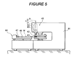
- Figure 5 shows a press machine that is an example of a machine tool having a linear motor device mounted thereon and using the linear motor as a driving source.
- the press machine has tool supports 42, 43 and a workpiece feeding mechanism 44 installed in a lower part of a frame 41, and the linear motor device installed in an upper part of the frame 41 as drive means for allowing press processing means 45 to perform a reciprocating operation; the linear motor device is composed of the linear motor 1 and the control section 30 in accordance with the first embodiment.
- the tool supports 42, 43 are composed of an upper turret and a lower turret, respectively, which are concentrically installed. Punch tools and die tools are mounted on the upper tool support 42 and the lower tool support 43, respectively, at a plurality positions in a circumferential direction. The tool supports 42, 43 are rotated to index any of the punch tools and die tools to a predetermined punch position P.
- the workpiece feeding mechanism 44 uses a work holder 47 to grip an edge of a plate-like workpiece W and moves the workpiece forward, backward, rightward, or leftward on a table 48.
- the press processing means 45 supports a ram 49 elevating and lowering the punch tool indexed to the punch position P on the tool support 42 so that the ram 49 can be freely elevated and lowered by a ram guide 50.
- the press mechanism 45 thus drivingly elevates and lowers the ram 49 by means of the linear motor 1.
- the coil member 3 of the linear motor 1 is fixed to the frame 41.
- the magnet member 2 of the linear motor 1 is fixed to the ram 49, which is a movable portion.
- the press machine configured as described above uses the linear motor 1 as drive means for the press processing means 45.
- the press machine eliminates the need for a mechanism converting rotation into the rectilinear motion of the ram 49 compared to a press machine using a rotary motor.
- the press mechanism 45 thus has a reduced number of parts and thus a simplified configuration.
- the present press machine also eliminates the need for a hydraulic unit compared to a press machine using a hydraulic cylinder as a press driving source. This simplifies the configuration.
- the linear motor 1 has a high positional accuracy, enabling processing with improved quality and accuracy.
- control section 30 performs control such that the magnet member 2 reciprocates within the use range L, corresponding to the part of the pitch (p) between the magnetic poles N and S in the magnet member 2 as described above.
- the magnet member 2 thus reciprocates within the range in which the attractive force does not vary significantly. This reduces the variation in thrust caused by the variation in attractive force, thus reducing the degradation of press processing quality caused by the variation in attractive force.
- the linear motor device in accordance with the present invention is not limited to a ring-shaped type in which the coil member 3 surrounds the magnet member 2.
- the magnet member 2 may be located parallel to the coil member.
- the machine tool having the linear motor device mounted thereon in accordance with the present invention is not limited to the press machine.
- the present invention is applicable to machine tools in general comprising processing means for processing a workpiece and drive means for reciprocating the processing means, wherein the linear motor device in accordance with the present invention is used as the drive means.
- the linear motor device in accordance with the present invention can be used as a driving source not only for machine tools but also for various types of equipment.
Landscapes
- Engineering & Computer Science (AREA)
- Physics & Mathematics (AREA)
- Electromagnetism (AREA)
- Power Engineering (AREA)
- Chemical & Material Sciences (AREA)
- Combustion & Propulsion (AREA)
- Mechanical Engineering (AREA)
- Microelectronics & Electronic Packaging (AREA)
- Linear Motors (AREA)
- Press Drives And Press Lines (AREA)
Applications Claiming Priority (1)
| Application Number | Priority Date | Filing Date | Title |
|---|---|---|---|
| JP2006264353A JP5100073B2 (ja) | 2006-09-28 | 2006-09-28 | リニアモータ装置およびそれを搭載した工作機械 |
Publications (3)
| Publication Number | Publication Date |
|---|---|
| EP1906514A2 true EP1906514A2 (de) | 2008-04-02 |
| EP1906514A3 EP1906514A3 (de) | 2010-12-15 |
| EP1906514B1 EP1906514B1 (de) | 2016-12-14 |
Family
ID=38561520
Family Applications (1)
| Application Number | Title | Priority Date | Filing Date |
|---|---|---|---|
| EP07017229.1A Ceased EP1906514B1 (de) | 2006-09-28 | 2007-09-03 | Linearmotor und Werkzeugmaschine mit darauf montiertem Linearmotor |
Country Status (6)
| Country | Link |
|---|---|
| US (1) | US7906877B2 (de) |
| EP (1) | EP1906514B1 (de) |
| JP (1) | JP5100073B2 (de) |
| KR (1) | KR101064546B1 (de) |
| CN (1) | CN101154876B (de) |
| TW (1) | TW200849773A (de) |
Cited By (3)
| Publication number | Priority date | Publication date | Assignee | Title |
|---|---|---|---|---|
| EP2329944A3 (de) * | 2009-12-03 | 2013-09-18 | Andritz Technology and Asset Management GmbH | Presse zum Erzeugen einer Druckkraft für die Bearbeitung eines Werkstückes |
| EP2288003A4 (de) * | 2008-04-16 | 2014-12-17 | Totankako Co Ltd | Anschlussleitungs-einbettungsvorrichtung und anschlussleitungs-einbettungsverfahren |
| EP2784920A3 (de) * | 2013-03-26 | 2016-09-07 | Sanyo Denki Co., Ltd. | Linearmotor |
Families Citing this family (23)
| Publication number | Priority date | Publication date | Assignee | Title |
|---|---|---|---|---|
| JP5100073B2 (ja) * | 2006-09-28 | 2012-12-19 | 村田機械株式会社 | リニアモータ装置およびそれを搭載した工作機械 |
| EP2110921B1 (de) * | 2008-04-14 | 2013-06-19 | Stanley Black & Decker, Inc. | Batterieverwaltungssystem für ein kabelloses Werkzeug |
| JP5486874B2 (ja) * | 2009-08-28 | 2014-05-07 | Thk株式会社 | 分散配置リニアモータおよび分散配置リニアモータの制御方法 |
| JP5077717B2 (ja) * | 2010-04-12 | 2012-11-21 | 村田機械株式会社 | 磁極検出システム |
| JP5146855B2 (ja) * | 2010-08-09 | 2013-02-20 | 村田機械株式会社 | 天井走行車システム |
| US8901783B2 (en) * | 2010-08-24 | 2014-12-02 | Qualcomm Incorporated | Handheld device force induction |
| US8888595B2 (en) | 2010-08-24 | 2014-11-18 | Qualcomm Incorporated | Inducing force into a non-anchored gaming device |
| CN102562880B (zh) * | 2010-12-30 | 2014-08-06 | 财团法人车辆研究测试中心 | 车用线性致动装置 |
| US8604647B2 (en) * | 2011-03-21 | 2013-12-10 | Automotive Research & Testing Center | Linear actuating device for vehicle use |
| JP5756445B2 (ja) * | 2012-01-26 | 2015-07-29 | オークマ株式会社 | リニアモータの制御方法 |
| CN102555258A (zh) * | 2012-02-24 | 2012-07-11 | 苏州大学 | 永磁助力机械增力电磁冲压机 |
| US9343931B2 (en) | 2012-04-06 | 2016-05-17 | David Deak | Electrical generator with rotational gaussian surface magnet and stationary coil |
| DE102013226826A1 (de) * | 2013-12-20 | 2015-06-25 | Robert Bosch Gmbh | Linearmotoranordnung und Werkzeugmaschine mit einer Linearmotoranordnung |
| CN108400629B (zh) | 2014-05-18 | 2023-01-24 | 百得有限公司 | 电池组 |
| US9893384B2 (en) | 2014-05-18 | 2018-02-13 | Black & Decker Inc. | Transport system for convertible battery pack |
| JP6005803B2 (ja) * | 2014-07-25 | 2016-10-12 | Thk株式会社 | リニアモータ装置及び制御方法 |
| US9673683B2 (en) * | 2014-11-07 | 2017-06-06 | David Deak, SR. | Reciprocating magnet electrical generator |
| US10444034B2 (en) * | 2016-04-27 | 2019-10-15 | Honeywell International Inc. | Linear actuator with position indicator |
| WO2018119256A1 (en) | 2016-12-23 | 2018-06-28 | Black & Decker Inc. | Cordless power tool system |
| EP3704785B1 (de) | 2017-10-30 | 2024-07-03 | WePower Technologies LLC | Magnetimpulsübertragsgenerator |
| US11368079B2 (en) | 2019-11-06 | 2022-06-21 | David Deak, SR. | Offset triggered cantilever actuated generator |
| CN115053437A (zh) | 2019-11-21 | 2022-09-13 | 威能科技有限责任公司 | 切向致动的磁动量传输发电机 |
| JP7691811B2 (ja) * | 2020-03-10 | 2025-06-12 | 株式会社プロテリアル | リニアモータ |
Family Cites Families (29)
| Publication number | Priority date | Publication date | Assignee | Title |
|---|---|---|---|---|
| US4363980A (en) * | 1979-06-05 | 1982-12-14 | Polaroid Corporation | Linear motor |
| US4349757A (en) * | 1980-05-08 | 1982-09-14 | Mechanical Technology Incorporated | Linear oscillating electric machine with permanent magnet excitation |
| US4870306A (en) * | 1981-10-08 | 1989-09-26 | Polaroid Corporation | Method and apparatus for precisely moving a motor armature |
| JPS627364A (ja) * | 1985-07-01 | 1987-01-14 | Shinko Electric Co Ltd | リニアパルスモ−タの磁極構造 |
| JPH01164256A (ja) * | 1987-12-18 | 1989-06-28 | Aisin Seiki Co Ltd | リニア発電機 |
| JP2610187B2 (ja) * | 1989-04-28 | 1997-05-14 | 株式会社いすゞセラミックス研究所 | バルブの駆動装置 |
| US5357779A (en) * | 1990-09-07 | 1994-10-25 | Coors Brewing Company | Can body maker with magnetic ram bearing and redraw actuator |
| US5212977A (en) * | 1991-07-16 | 1993-05-25 | Aura Systems, Inc. | Electromagnetic re-draw sleeve actuator |
| US5175457A (en) * | 1991-10-28 | 1992-12-29 | Mechanical Technology Incorporated | Linear motor or alternator plunger configuration using variable magnetic properties for center row and outer rows of magnets |
| JP3302727B2 (ja) * | 1992-07-20 | 2002-07-15 | ティーディーケイ株式会社 | 可動磁石式アクチュエータ |
| US5691582A (en) * | 1993-03-23 | 1997-11-25 | Coors Brewing Company | Can body maker with linear motor redraw actuator |
| JPH06335230A (ja) * | 1993-05-18 | 1994-12-02 | Hitachi Metals Ltd | 永久磁石式リニア同期モータ |
| US5808381A (en) * | 1994-08-09 | 1998-09-15 | Hitachi Metals, Ltd. | Linear motor |
| JPH08275498A (ja) * | 1995-03-31 | 1996-10-18 | Minolta Co Ltd | リニアモータ |
| JPH10313566A (ja) | 1997-05-12 | 1998-11-24 | Jii M C:Kk | リニアモータ |
| JP2001520498A (ja) * | 1997-10-15 | 2001-10-30 | アドバンスト モーション テクノロジーズ リミテッド ライアビリティー カンパニー | リニア電磁機械 |
| JP3732355B2 (ja) * | 1999-04-28 | 2006-01-05 | 株式会社ソディック | プレス機械 |
| IT1309797B1 (it) * | 1999-05-06 | 2002-01-30 | Boscato & Dalla Fontana | Meccanismo maschietto per la pressatura di gocce di vetro fusodentro lo stampo sbozzatore di una macchina i.s. per la produzione |
| US6363750B1 (en) * | 2000-02-25 | 2002-04-02 | Chris D. Chiodo | Automatic pipette puller and forge |
| JP2001352747A (ja) * | 2000-06-09 | 2001-12-21 | Aida Eng Ltd | リニアモータおよびこれを駆動源とするプレス成形装置 |
| US6701748B1 (en) * | 2000-10-06 | 2004-03-09 | Libbey Glass Inc. | Glassware machine |
| JP2004040874A (ja) * | 2002-07-01 | 2004-02-05 | Nikon Corp | リニアモータ及びステージ装置並びに露光装置 |
| ITBO20030163A1 (it) * | 2003-03-25 | 2004-09-26 | Gd Spa | Motore elettrico lineare. |
| JP2004364399A (ja) * | 2003-06-04 | 2004-12-24 | Sankyo Seiki Mfg Co Ltd | リニアモータ |
| US7242118B2 (en) * | 2003-07-31 | 2007-07-10 | Japan Servo Co., Ltd. | Toroidal-coil linear stepping motor, toroidal-coil linear reciprocating motor, cylinder compressor and cylinder pump using these motors |
| US7378765B2 (en) * | 2004-08-09 | 2008-05-27 | Oriental Motor Co., Ltd. | Cylinder-type linear motor and moving part thereof |
| US7482717B2 (en) * | 2006-06-15 | 2009-01-27 | Hochhalter Keith W | Servo actuator with self positioning rotor and method |
| US7434442B2 (en) * | 2006-08-16 | 2008-10-14 | Werth Advanced Packaging Innovations, Ltd. | Container bodymaker |
| JP5100073B2 (ja) * | 2006-09-28 | 2012-12-19 | 村田機械株式会社 | リニアモータ装置およびそれを搭載した工作機械 |
-
2006
- 2006-09-28 JP JP2006264353A patent/JP5100073B2/ja not_active Expired - Fee Related
-
2007
- 2007-09-03 EP EP07017229.1A patent/EP1906514B1/de not_active Ceased
- 2007-09-07 TW TW96133546A patent/TW200849773A/zh unknown
- 2007-09-19 KR KR1020070095456A patent/KR101064546B1/ko not_active Expired - Fee Related
- 2007-09-25 US US11/902,804 patent/US7906877B2/en not_active Expired - Fee Related
- 2007-09-28 CN CN2007101531510A patent/CN101154876B/zh not_active Expired - Fee Related
Cited By (4)
| Publication number | Priority date | Publication date | Assignee | Title |
|---|---|---|---|---|
| EP2288003A4 (de) * | 2008-04-16 | 2014-12-17 | Totankako Co Ltd | Anschlussleitungs-einbettungsvorrichtung und anschlussleitungs-einbettungsverfahren |
| EP2329944A3 (de) * | 2009-12-03 | 2013-09-18 | Andritz Technology and Asset Management GmbH | Presse zum Erzeugen einer Druckkraft für die Bearbeitung eines Werkstückes |
| AT509090B1 (de) * | 2009-12-03 | 2014-03-15 | Andritz Tech & Asset Man Gmbh | Presse zum erzeugen einer druckkraft für die bearbeitung eines werkstücks |
| EP2784920A3 (de) * | 2013-03-26 | 2016-09-07 | Sanyo Denki Co., Ltd. | Linearmotor |
Also Published As
| Publication number | Publication date |
|---|---|
| JP2008086145A (ja) | 2008-04-10 |
| TW200849773A (en) | 2008-12-16 |
| KR101064546B1 (ko) | 2011-09-14 |
| EP1906514A3 (de) | 2010-12-15 |
| KR20080029816A (ko) | 2008-04-03 |
| CN101154876B (zh) | 2011-10-05 |
| CN101154876A (zh) | 2008-04-02 |
| EP1906514B1 (de) | 2016-12-14 |
| US7906877B2 (en) | 2011-03-15 |
| JP5100073B2 (ja) | 2012-12-19 |
| US20080079319A1 (en) | 2008-04-03 |
Similar Documents
| Publication | Publication Date | Title |
|---|---|---|
| US7906877B2 (en) | Linear motor device and machine tool having the same mounted thereon | |
| US7768159B2 (en) | Linear motor and machine tool having the same mounted thereon | |
| US7752880B2 (en) | Linear motor mounted press machine and method for controlling linear motor mounted press machine | |
| US7523699B2 (en) | Linear motor mounted press machine and method for controlling linear motor mounted press machine | |
| US5284411A (en) | Conveyor for conveying workpieces in a vacuum chamber | |
| EP1977853A1 (de) | Magnetlagerspindelvorrichtung für Maschinenwerkzeuge | |
| US7642678B2 (en) | Linear motor and machine tool having the same mounted thereon | |
| JPWO2005122368A1 (ja) | ムービングマグネット形リニアスライダ | |
| US20080041243A1 (en) | Linear motor mounted press machine and press working method | |
| JP2007130712A (ja) | 加工装置 | |
| EP1892819A2 (de) | Mehrfach-Linearmotor und Werkzeugmaschine mit darauf montiertem Mehrfach-Linearmotor | |
| JP2016022536A (ja) | 機構分割式無心インデックス装置 | |
| JP2008048564A (ja) | リニアモータおよびそれを搭載した工作機械 | |
| KR20070021183A (ko) | 무빙 마그넷형 리니어 슬라이더 | |
| JP2008048567A (ja) | リニアモータおよびそれを搭載した工作機械 | |
| JP5916802B2 (ja) | 旋削加工装置の工具送り装置 | |
| GB2033276A (en) | A High Speed Press | |
| JP2008043994A (ja) | リニアモータ搭載プレス機械 |
Legal Events
| Date | Code | Title | Description |
|---|---|---|---|
| PUAI | Public reference made under article 153(3) epc to a published international application that has entered the european phase |
Free format text: ORIGINAL CODE: 0009012 |
|
| AK | Designated contracting states |
Kind code of ref document: A2 Designated state(s): AT BE BG CH CY CZ DE DK EE ES FI FR GB GR HU IE IS IT LI LT LU LV MC MT NL PL PT RO SE SI SK TR |
|
| AX | Request for extension of the european patent |
Extension state: AL BA HR MK YU |
|
| PUAL | Search report despatched |
Free format text: ORIGINAL CODE: 0009013 |
|
| AK | Designated contracting states |
Kind code of ref document: A3 Designated state(s): AT BE BG CH CY CZ DE DK EE ES FI FR GB GR HU IE IS IT LI LT LU LV MC MT NL PL PT RO SE SI SK TR |
|
| AX | Request for extension of the european patent |
Extension state: AL BA HR MK RS |
|
| 17P | Request for examination filed |
Effective date: 20110401 |
|
| AKX | Designation fees paid |
Designated state(s): DE IT |
|
| RAP1 | Party data changed (applicant data changed or rights of an application transferred) |
Owner name: MURATA MACHINERY, LTD. |
|
| REG | Reference to a national code |
Ref country code: DE Ref legal event code: R079 Ref document number: 602007049109 Country of ref document: DE Free format text: PREVIOUS MAIN CLASS: H02K0041030000 Ipc: H02K0007106000 |
|
| GRAP | Despatch of communication of intention to grant a patent |
Free format text: ORIGINAL CODE: EPIDOSNIGR1 |
|
| RIC1 | Information provided on ipc code assigned before grant |
Ipc: B30B 1/42 20060101ALI20160429BHEP Ipc: H02K 7/106 20060101AFI20160429BHEP Ipc: H02K 41/03 20060101ALI20160429BHEP Ipc: H02K 7/118 20060101ALI20160429BHEP Ipc: H02K 11/21 20160101ALI20160429BHEP |
|
| RIN1 | Information on inventor provided before grant (corrected) |
Inventor name: ISHIYAMA, NORITAKA Inventor name: OKADA, TAKUYA |
|
| INTG | Intention to grant announced |
Effective date: 20160602 |
|
| GRAJ | Information related to disapproval of communication of intention to grant by the applicant or resumption of examination proceedings by the epo deleted |
Free format text: ORIGINAL CODE: EPIDOSDIGR1 |
|
| GRAP | Despatch of communication of intention to grant a patent |
Free format text: ORIGINAL CODE: EPIDOSNIGR1 |
|
| INTC | Intention to grant announced (deleted) | ||
| INTG | Intention to grant announced |
Effective date: 20160729 |
|
| GRAS | Grant fee paid |
Free format text: ORIGINAL CODE: EPIDOSNIGR3 |
|
| GRAA | (expected) grant |
Free format text: ORIGINAL CODE: 0009210 |
|
| AK | Designated contracting states |
Kind code of ref document: B1 Designated state(s): DE IT |
|
| REG | Reference to a national code |
Ref country code: DE Ref legal event code: R096 Ref document number: 602007049109 Country of ref document: DE |
|
| PG25 | Lapsed in a contracting state [announced via postgrant information from national office to epo] |
Ref country code: IT Free format text: LAPSE BECAUSE OF FAILURE TO SUBMIT A TRANSLATION OF THE DESCRIPTION OR TO PAY THE FEE WITHIN THE PRESCRIBED TIME-LIMIT Effective date: 20161214 |
|
| REG | Reference to a national code |
Ref country code: DE Ref legal event code: R097 Ref document number: 602007049109 Country of ref document: DE |
|
| PLBE | No opposition filed within time limit |
Free format text: ORIGINAL CODE: 0009261 |
|
| STAA | Information on the status of an ep patent application or granted ep patent |
Free format text: STATUS: NO OPPOSITION FILED WITHIN TIME LIMIT |
|
| 26N | No opposition filed |
Effective date: 20170915 |
|
| PGFP | Annual fee paid to national office [announced via postgrant information from national office to epo] |
Ref country code: DE Payment date: 20180920 Year of fee payment: 12 |
|
| REG | Reference to a national code |
Ref country code: DE Ref legal event code: R119 Ref document number: 602007049109 Country of ref document: DE |
|
| PG25 | Lapsed in a contracting state [announced via postgrant information from national office to epo] |
Ref country code: DE Free format text: LAPSE BECAUSE OF NON-PAYMENT OF DUE FEES Effective date: 20200401 |