EP1906832B1 - Systeme d'imagerie utilisant de la lumiere infrarouge diffuse - Google Patents
Systeme d'imagerie utilisant de la lumiere infrarouge diffuse Download PDFInfo
- Publication number
- EP1906832B1 EP1906832B1 EP00978736.7A EP00978736A EP1906832B1 EP 1906832 B1 EP1906832 B1 EP 1906832B1 EP 00978736 A EP00978736 A EP 00978736A EP 1906832 B1 EP1906832 B1 EP 1906832B1
- Authority
- EP
- European Patent Office
- Prior art keywords
- body tissue
- infrared light
- light
- video
- enclosure
- Prior art date
- Legal status (The legal status is an assumption and is not a legal conclusion. Google has not performed a legal analysis and makes no representation as to the accuracy of the status listed.)
- Expired - Lifetime
Links
- 238000003384 imaging method Methods 0.000 title claims description 44
- 238000005286 illumination Methods 0.000 claims description 31
- 210000004204 blood vessel Anatomy 0.000 claims description 22
- 238000007920 subcutaneous administration Methods 0.000 claims description 12
- 230000000007 visual effect Effects 0.000 claims description 10
- 238000000034 method Methods 0.000 claims description 7
- 230000002708 enhancing effect Effects 0.000 claims description 5
- 210000001519 tissue Anatomy 0.000 description 30
- 210000004003 subcutaneous fat Anatomy 0.000 description 5
- 239000008280 blood Substances 0.000 description 1
- 210000004369 blood Anatomy 0.000 description 1
- 238000002059 diagnostic imaging Methods 0.000 description 1
- 238000010586 diagram Methods 0.000 description 1
- 230000005670 electromagnetic radiation Effects 0.000 description 1
- 229910052736 halogen Inorganic materials 0.000 description 1
- 238000012986 modification Methods 0.000 description 1
- 230000004048 modification Effects 0.000 description 1
- 230000003287 optical effect Effects 0.000 description 1
- 230000005855 radiation Effects 0.000 description 1
- 238000011282 treatment Methods 0.000 description 1
Images




Classifications
-
- A—HUMAN NECESSITIES
- A61—MEDICAL OR VETERINARY SCIENCE; HYGIENE
- A61B—DIAGNOSIS; SURGERY; IDENTIFICATION
- A61B5/00—Measuring for diagnostic purposes; Identification of persons
- A61B5/48—Other medical applications
- A61B5/4887—Locating particular structures in or on the body
- A61B5/489—Blood vessels
-
- A—HUMAN NECESSITIES
- A61—MEDICAL OR VETERINARY SCIENCE; HYGIENE
- A61B—DIAGNOSIS; SURGERY; IDENTIFICATION
- A61B5/00—Measuring for diagnostic purposes; Identification of persons
- A61B5/0059—Measuring for diagnostic purposes; Identification of persons using light, e.g. diagnosis by transillumination, diascopy, fluorescence
-
- H—ELECTRICITY
- H04—ELECTRIC COMMUNICATION TECHNIQUE
- H04N—PICTORIAL COMMUNICATION, e.g. TELEVISION
- H04N23/00—Cameras or camera modules comprising electronic image sensors; Control thereof
- H04N23/20—Cameras or camera modules comprising electronic image sensors; Control thereof for generating image signals from infrared radiation only
- H04N23/21—Cameras or camera modules comprising electronic image sensors; Control thereof for generating image signals from infrared radiation only from near infrared [NIR] radiation
-
- H—ELECTRICITY
- H04—ELECTRIC COMMUNICATION TECHNIQUE
- H04N—PICTORIAL COMMUNICATION, e.g. TELEVISION
- H04N23/00—Cameras or camera modules comprising electronic image sensors; Control thereof
- H04N23/70—Circuitry for compensating brightness variation in the scene
- H04N23/74—Circuitry for compensating brightness variation in the scene by influencing the scene brightness using illuminating means
-
- A—HUMAN NECESSITIES
- A61—MEDICAL OR VETERINARY SCIENCE; HYGIENE
- A61B—DIAGNOSIS; SURGERY; IDENTIFICATION
- A61B90/00—Instruments, implements or accessories specially adapted for surgery or diagnosis and not covered by any of the groups A61B1/00 - A61B50/00, e.g. for luxation treatment or for protecting wound edges
- A61B90/36—Image-producing devices or illumination devices not otherwise provided for
- A61B2090/364—Correlation of different images or relation of image positions in respect to the body
- A61B2090/366—Correlation of different images or relation of image positions in respect to the body using projection of images directly onto the body
-
- A—HUMAN NECESSITIES
- A61—MEDICAL OR VETERINARY SCIENCE; HYGIENE
- A61B—DIAGNOSIS; SURGERY; IDENTIFICATION
- A61B5/00—Measuring for diagnostic purposes; Identification of persons
- A61B5/0059—Measuring for diagnostic purposes; Identification of persons using light, e.g. diagnosis by transillumination, diascopy, fluorescence
- A61B5/0082—Measuring for diagnostic purposes; Identification of persons using light, e.g. diagnosis by transillumination, diascopy, fluorescence adapted for particular medical purposes
- A61B5/0084—Measuring for diagnostic purposes; Identification of persons using light, e.g. diagnosis by transillumination, diascopy, fluorescence adapted for particular medical purposes for introduction into the body, e.g. by catheters
- A61B5/0086—Measuring for diagnostic purposes; Identification of persons using light, e.g. diagnosis by transillumination, diascopy, fluorescence adapted for particular medical purposes for introduction into the body, e.g. by catheters using infrared radiation
Definitions
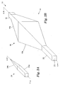
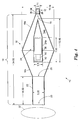
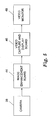
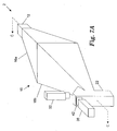
- FIG. 1 Shown in Fig. 1 is an imaging system 2 for illuminating an object 32, such as body tissue, with highly diffuse infrared light, and for producing a video image of the object 32 based upon infrared light reflected from the object 32.
- an imaging system 2 for illuminating an object 32, such as body tissue, with highly diffuse infrared light, and for producing a video image of the object 32 based upon infrared light reflected from the object 32.
- an imaging system 2 for illuminating an object 32, such as body tissue, with highly diffuse infrared light, and for producing a video image of the object 32 based upon infrared light reflected from the object 32.
- an imaging system 2 for illuminating an object 32, such as body tissue, with highly diffuse infrared light, and for producing a video image of the object 32 based upon infrared light reflected from the object 32.
- the infrared-transmitting filter 42 is mounted in a wall of the light guide 22.
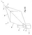
- a reflective panel 60 is provided in this embodiment to further direct the light from the light source 12 into the light guide 22 and toward the exit aperture 23.
- the panel 60 is a flat reflective sheet having an orifice therein to allow light to pass between the object 32 and the camera 38 and projector 50.
Landscapes
- Health & Medical Sciences (AREA)
- Life Sciences & Earth Sciences (AREA)
- Engineering & Computer Science (AREA)
- Heart & Thoracic Surgery (AREA)
- Molecular Biology (AREA)
- Physics & Mathematics (AREA)
- Signal Processing (AREA)
- Biophysics (AREA)
- Pathology (AREA)
- Biomedical Technology (AREA)
- Multimedia (AREA)
- Medical Informatics (AREA)
- Veterinary Medicine (AREA)
- Surgery (AREA)
- Animal Behavior & Ethology (AREA)
- General Health & Medical Sciences (AREA)
- Public Health (AREA)
- Toxicology (AREA)
- Vascular Medicine (AREA)
- Investigating Or Analysing Materials By Optical Means (AREA)
- Studio Devices (AREA)
- Measurement Of The Respiration, Hearing Ability, Form, And Blood Characteristics Of Living Organisms (AREA)
Claims (14)
- Système d'imagerie (2) pour la visualisation de tissu corporel sous éclairage infrarouge pour améliorer la visibilité des vaisseaux sanguins sous-cutanés, caractérisé en ce que le système (2) comprend :un moyen (10) destiné à éclairer le tissu corporel avec une lumière infrarouge diffuse, la lumière infrarouge arrivant au niveau du tissu corporel à partir d'une pluralité de directions d'éclairage différentes, ce qui permet de fournir une lumière infrarouge diffuse au tissu corporel ; etun moyen d'imagerie vidéo (38) pour la visualisation du tissu corporel à partir d'une direction de visualisation (6), pour la réception de la lumière infrarouge diffuse réfléchie à partir du tissu corporel, et pour la génération d'une image vidéo du tissu corporel sur la base de la lumière infrarouge diffuse réfléchie à partir du tissu corporel.
- Système (2) de la revendication 1, dans lequel le moyen (10) destiné à éclairer le tissu corporel avec une lumière infrarouge qui arrive au niveau du tissu corporel à partir d'une pluralité de directions d'éclairage différentes comprend une pluralité de sources de lumière infrarouge (10a-10f), chacune fournissant la lumière infrarouge au tissu corporel à partir d'au moins l'une des directions d'éclairage différentes.
- Système (2) de la revendication 1, dans lequel le moyen (10) destiné à éclairer le tissu corporel avec une lumière infrarouge à partir d'une pluralité de directions d'éclairage différentes comprend :une source de lumière infrarouge (12) destinée à générer la lumière infrarouge ; etun moyen (14) destiné à diffuser la lumière infrarouge ayant :une ouverture d'entrée (18) permettant de recevoir la lumière infrarouge à partir de la source de lumière infrarouge (12) ;une pluralité de surfaces réfléchissantes destinées à réfléchir la lumière infrarouge plusieurs fois et dans plusieurs directions de réflexion, ce qui permet de produire une lumière infrarouge diffuse ; etune ouverture de sortie (20) permettant de recevoir la lumière infrarouge diffuse réfléchie à partir de la pluralité de surfaces réfléchissantes et permettant d'émettre la lumière infrarouge diffuse vers le tissu corporel.
- Système (2) de la revendication 3, dans lequel le moyen (14) destiné à diffuser la lumière infrarouge comprend :une enceinte externe allongée (16) ayant des surfaces internes réfléchissantes, et ayant une première extrémité d'enceinte externe (16a) et une deuxième extrémité d'enceinte externe (16b) ;l'ouverture d'entrée (18) disposée au niveau de la première extrémité d'enceinte externe (16a) ;l'ouverture de sortie (20) disposée au niveau de la deuxième extrémité d'enceinte externe (16b) ; etune enceinte interne allongée (24) disposée à l'intérieur de l'enceinte externe (16) et entre les première et deuxième extrémités d'enceinte externe (16a, 16b), l'enceinte interne (24) ayant des surfaces externes réfléchissantes faisant face aux surfaces internes de l'enceinte externe (16).
- Système (2) de la revendication 4, comprenant en outre :l'enceinte interne allongée (24) ayant :une première extrémité d'enceinte interne (24b) disposée à proximité de la première extrémité d'enceinte externe (16a) ;une deuxième extrémité d'enceinte interne (24a) disposée à proximité de la deuxième extrémité d'enceinte externe (16b) ; etune ouverture d'enceinte interne disposée au niveau de la deuxième extrémité d'enceinte interne (24a) ; etun moyen d'imagerie vidéo (38) disposé à l'intérieur de l'enceinte interne (24) permettant de recevoir la lumière infrarouge diffuse réfléchie à partir du tissu corporel à travers l'ouverture d'enceinte interne.
- Système (2) de la revendication 5, comprenant en outre :un moyen de filtrage (42) disposé au niveau de l'ouverture d'enceinte interne pour recevoir une lumière réfléchie à partir du tissu corporel, et pour atténuer toute partie de la lumière ayant des longueurs d'onde en dehors d'un domaine infrarouge de longueurs d'onde pour produire une lumière infrarouge filtrée ; etle moyen d'imagerie vidéo (38) permettant de recevoir la lumière infrarouge filtrée à partir du moyen de filtrage (42), et permettant de générer l'image vidéo de l'objet sur la base de la lumière infrarouge filtrée.
- Système (2) de la revendication 4, dans lequel l'enceinte externe allongée (16) comprend en outre :une première section essentiellement pyramidale ayant une petite extrémité de première section pyramidale et une grande extrémité de première section pyramidale, la première extrémité d'enceinte externe (16a) incorporant la petite extrémité de première section pyramidale ;une deuxième section essentiellement pyramidale ayant une grande extrémité de deuxième section pyramidale et une petite extrémité de deuxième section pyramidale, la grande extrémité de deuxième section pyramidale attenante à la grande extrémité de première section pyramidale ; etune section tubulaire externe ayant une première extrémité de section tubulaire externe et une deuxième extrémité de section tubulaire externe, la première extrémité de section tubulaire externe attenante à la grande extrémité de deuxième section pyramidale, la deuxième extrémité d'enceinte externe incorporant la deuxième extrémité tubulaire externe.
- Système (2) de la revendication 7, dans lequel l'enceinte interne allongée (24) comprend en outre :une troisième section pyramidale ayant une petite extrémité de troisième section pyramidale et une grande extrémité de troisième section pyramidale, la première extrémité d'enceinte interne incorporant la petite extrémité de troisième section pyramidale ; etune section tubulaire interne ayant une première extrémité de section tubulaire interne et une deuxième extrémité de section tubulaire interne, la première extrémité de section tubulaire interne attenante à la grande extrémité de troisième section pyramidale, et la deuxième extrémité d'enceinte interne incorporant la deuxième extrémité de section tubulaire interne.
- Système (2) de la revendication 1, comprenant en outre :un moyen de filtrage (42) destiné à recevoir une lumière réfléchie à partir du tissu corporel, à transmettre une lumière ayant des longueurs d'onde dans un domaine infrarouge de longueurs d'onde, et à réfléchir une lumière ayant des longueurs d'onde en dehors du domaine infrarouge de longueurs d'onde pour produire une lumière infrarouge filtrée ; etle moyen d'imagerie vidéo (38) permettant de recevoir la lumière infrarouge filtrée à partir du moyen de filtrage (42), et permettant de générer l'image vidéo du tissu corporel sur la base de la lumière infrarouge filtrée réfléchie à partir du tissu corporel.
- Système (2) de la revendication 9, dans lequel le moyen de filtrage (42) empêche essentiellement une lumière ayant des longueurs d'onde inférieures à 700 nanomètres et supérieures à 1000 nanomètres d'atteindre le moyen d'imagerie vidéo (38).
- Système (2) de la revendication 4, comprenant en outre :un vidéoprojecteur (50) permettant de projeter une image en lumière visible du tissu corporel sur la base de l'image vidéo du tissu corporel générée par le moyen d'imagerie vidéo (38) ; etun séparateur de faisceau (54) destiné à recevoir la lumière infrarouge diffuse à partir de l'ouverture de sortie et à réfléchir la lumière infrarouge diffuse vers le tissu corporel, à recevoir l'image en lumière visible à partir du vidéoprojecteur (50) et à transmettre l'image en lumière visible vers le tissu corporel, et à recevoir la lumière infrarouge réfléchie à partir du tissu corporel et à réfléchir la lumière réfléchie à partir du tissu corporel vers le moyen d'imagerie vidéo (38).
- Système (2) de la revendication 4, comprenant en outre :un vidéoprojecteur (50) permettant de projeter une image en lumière visible du tissu corporel sur la base de l'image vidéo du tissu corporel générée par le moyen d'imagerie vidéo (38) ; etun séparateur de faisceau (54) destiné à recevoir la lumière infrarouge diffuse à partir de l'ouverture de sortie et à transmettre la lumière infrarouge diffuse vers le tissu corporel, à recevoir l'image en lumière visible à partir du vidéoprojecteur (50) et à réfléchir l'image en lumière visible vers le tissu corporel, et à recevoir la lumière infrarouge réfléchie à partir du tissu corporel et à réfléchir la lumière réfléchie à partir du tissu corporel vers le moyen d'imagerie vidéo (38).
- Procédé pour la visualisation de tissu corporel sous éclairage infrarouge pour améliorer la visibilité des vaisseaux sanguins sous-cutanés, caractérisé en ce que le procédé comprend le fait :de fournir une lumière infrarouge diffuse au tissu corporel, la lumière infrarouge arrivant au niveau du tissu corporel à partir d'une pluralité de directions d'éclairage différentes, ce qui permet d'éclairer le tissu corporel avec une lumière infrarouge diffuse ;de visualiser le tissu corporel à partir d'une direction de visualisation (6) en utilisant un dispositif d'imagerie vidéo (38) ;de générer une image vidéo du tissu corporel en utilisant le dispositif d'imagerie vidéo (38) sur la base d'une lumière infrarouge réfléchie à partir du tissu corporel ; etd'utiliser l'image vidéo du tissu corporel pour trouver les vaisseaux sanguins sous-cutanés.
- Procédé de la revendication 13, comprenant en outre le fait de projeter sur le tissu corporel une image en lumière visible du tissu corporel, où l'image en lumière visible est basée sur l'image vidéo du tissu corporel générée par le moyen d'imagerie vidéo (38), ce qui permet d'améliorer un contraste visuel entre des zones claires et sombres du tissu corporel telles que détectées par un observateur direct du tissu corporel.
Priority Applications (1)
| Application Number | Priority Date | Filing Date | Title |
|---|---|---|---|
| DE20023810U DE20023810U1 (de) | 2000-01-19 | 2000-11-17 | Abbildungssystem unter Verwendung von diffusem Infrarotlicht |
Applications Claiming Priority (2)
| Application Number | Priority Date | Filing Date | Title |
|---|---|---|---|
| US09/487,007 US6556858B1 (en) | 2000-01-19 | 2000-01-19 | Diffuse infrared light imaging system |
| PCT/US2000/031534 WO2001054393A2 (fr) | 2000-01-19 | 2000-11-17 | Systeme d'imagerie utilisant de la lumiere infrarouge diffuse |
Related Child Applications (1)
| Application Number | Title | Priority Date | Filing Date |
|---|---|---|---|
| EP10184555.0 Division-Into | 2010-09-30 |
Publications (3)
| Publication Number | Publication Date |
|---|---|
| EP1906832A2 EP1906832A2 (fr) | 2008-04-09 |
| EP1906832A4 EP1906832A4 (fr) | 2008-04-09 |
| EP1906832B1 true EP1906832B1 (fr) | 2013-08-28 |
Family
ID=23934025
Family Applications (1)
| Application Number | Title | Priority Date | Filing Date |
|---|---|---|---|
| EP00978736.7A Expired - Lifetime EP1906832B1 (fr) | 2000-01-19 | 2000-11-17 | Systeme d'imagerie utilisant de la lumiere infrarouge diffuse |
Country Status (6)
| Country | Link |
|---|---|
| US (1) | US6556858B1 (fr) |
| EP (1) | EP1906832B1 (fr) |
| JP (1) | JP4555534B2 (fr) |
| AU (1) | AU2001216166A1 (fr) |
| DE (1) | DE20023810U1 (fr) |
| WO (1) | WO2001054393A2 (fr) |
Families Citing this family (110)
| Publication number | Priority date | Publication date | Assignee | Title |
|---|---|---|---|---|
| US8078263B2 (en) * | 2000-01-19 | 2011-12-13 | Christie Medical Holdings, Inc. | Projection of subsurface structure onto an object's surface |
| US8494616B2 (en) | 2000-01-19 | 2013-07-23 | Christie Medical Holdings, Inc. | Method and apparatus for projection of subsurface structure onto an object's surface |
| US7239909B2 (en) | 2000-01-19 | 2007-07-03 | Luminetx Technologies Corp. | Imaging system using diffuse infrared light |
| JP3807721B2 (ja) * | 2000-02-21 | 2006-08-09 | シャープ株式会社 | 画像合成装置 |
| US7359748B1 (en) * | 2000-07-26 | 2008-04-15 | Rhett Drugge | Apparatus for total immersion photography |
| DE60336303D1 (de) * | 2002-01-30 | 2011-04-21 | Tyco Healthcare | Chirurgische bildgebende vorrichtung |
| EP1503330B1 (fr) | 2002-05-09 | 2010-06-02 | Sony Corporation | Procede pour identifier un modele biologique, detecteur de modele biologique, procede et dispositif pour etablir un certificat biologique |
| US20050119546A9 (en) * | 2002-07-31 | 2005-06-02 | Connell Reynolds | Systems and methods for locating blood vessels |
| US6914805B2 (en) * | 2002-08-21 | 2005-07-05 | Micron Technology, Inc. | Method for building a magnetic keeper or flux concentrator used for writing magnetic bits on a MRAM device |
| US20040215081A1 (en) * | 2003-04-23 | 2004-10-28 | Crane Robert L. | Method for detection and display of extravasation and infiltration of fluids and substances in subdermal or intradermal tissue |
| JP2008510559A (ja) * | 2004-08-27 | 2008-04-10 | コーニンクレッカ フィリップス エレクトロニクス エヌ ヴィ | 分光分析用の透過式撮像 |
| KR100612863B1 (ko) * | 2004-10-11 | 2006-08-14 | 삼성전자주식회사 | 체지방 측정 장치 및 방법 |
| US8548570B2 (en) | 2004-11-29 | 2013-10-01 | Hypermed Imaging, Inc. | Hyperspectral imaging of angiogenesis |
| JP5149015B2 (ja) * | 2004-12-28 | 2013-02-20 | ハイパーメツド・イメージング・インコーポレイテツド | 全身生理機能およびショックの決定、評価および監視におけるハイパースペクトル/マルチスペクトルイメージング |
| US20060173360A1 (en) * | 2005-01-07 | 2006-08-03 | Kalafut John F | Method for detection and display of extravasation and infiltration of fluids and substances in subdermal or intradermal tissue |
| JP4669713B2 (ja) * | 2005-02-18 | 2011-04-13 | 株式会社リコー | 画像読取装置及び画像形成装置 |
| CA2947613C (fr) | 2005-04-04 | 2019-11-05 | Hypermed Imaging, Inc. | Imagerie hyperspectrale mise en oeuvre chez des patients souffrant de diabete ou d'une maladie vasculaire peripherique |
| US7925332B2 (en) * | 2005-05-13 | 2011-04-12 | Infrared Imaging Systems, Inc. | Disposable light source patch for enhanced visualization of subcutaneous structures |
| US20100054545A1 (en) * | 2005-06-02 | 2010-03-04 | Larry Elliott | Method and apparatus for displaying properties onto an object or life form |
| ATE523145T1 (de) * | 2005-07-01 | 2011-09-15 | Luminetx Corp | Projektion von unteroberflächenstrukturen auf eine objektoberfläche |
| US20070038118A1 (en) * | 2005-08-10 | 2007-02-15 | Depue Marshall Thomas | Subcutaneous tissue imager |
| US8784336B2 (en) | 2005-08-24 | 2014-07-22 | C. R. Bard, Inc. | Stylet apparatuses and methods of manufacture |
| US8478386B2 (en) | 2006-01-10 | 2013-07-02 | Accuvein Inc. | Practitioner-mounted micro vein enhancer |
| US9492117B2 (en) | 2006-01-10 | 2016-11-15 | Accuvein, Inc. | Practitioner-mounted micro vein enhancer |
| US12295744B2 (en) | 2006-01-10 | 2025-05-13 | Accuvein, Inc. | Micro vein enhancer with two lasers and two optical detectors configured for removing surface topology |
| US12408865B2 (en) | 2006-01-10 | 2025-09-09 | Accuvein Inc. | Vein imaging device with differential image resolution at the center and the extremities of the vein image |
| US12471844B2 (en) | 2006-06-29 | 2025-11-18 | Accuvein, Inc. | Scanned laser vein contrast enhancer with full stopping of scanner movement during scan line reversals |
| US9854977B2 (en) | 2006-01-10 | 2018-01-02 | Accuvein, Inc. | Scanned laser vein contrast enhancer using a single laser, and modulation circuitry |
| US8255040B2 (en) | 2006-06-29 | 2012-08-28 | Accuvein, Llc | Micro vein enhancer |
| US10813588B2 (en) | 2006-01-10 | 2020-10-27 | Accuvein, Inc. | Micro vein enhancer |
| US12089951B2 (en) | 2006-01-10 | 2024-09-17 | AccuVeiw, Inc. | Scanned laser vein contrast enhancer with scanning correlated to target distance |
| US11278240B2 (en) | 2006-01-10 | 2022-03-22 | Accuvein, Inc. | Trigger-actuated laser vein contrast enhancer |
| US8489178B2 (en) | 2006-06-29 | 2013-07-16 | Accuvein Inc. | Enhanced laser vein contrast enhancer with projection of analyzed vein data |
| US11253198B2 (en) | 2006-01-10 | 2022-02-22 | Accuvein, Inc. | Stand-mounted scanned laser vein contrast enhancer |
| US10238294B2 (en) | 2006-06-29 | 2019-03-26 | Accuvein, Inc. | Scanned laser vein contrast enhancer using one laser |
| US8838210B2 (en) * | 2006-06-29 | 2014-09-16 | AccuView, Inc. | Scanned laser vein contrast enhancer using a single laser |
| US8649848B2 (en) * | 2006-03-28 | 2014-02-11 | The United States Of America, As Represented By The Secretary Of The Air Force | Synchronization of illumination source and sensor for improved visualization of subcutaneous structures |
| US8665507B2 (en) * | 2006-06-29 | 2014-03-04 | Accuvein, Inc. | Module mounting mirror endoscopy |
| US8463364B2 (en) * | 2009-07-22 | 2013-06-11 | Accuvein Inc. | Vein scanner |
| US8594770B2 (en) * | 2006-06-29 | 2013-11-26 | Accuvein, Inc. | Multispectral detection and presentation of an object's characteristics |
| US20160296146A9 (en) * | 2006-06-29 | 2016-10-13 | Fred Wood | Apparatus-Mounted Vein Contrast Enchancer |
| US8244333B2 (en) * | 2006-06-29 | 2012-08-14 | Accuvein, Llc | Scanned laser vein contrast enhancer |
| US8730321B2 (en) * | 2007-06-28 | 2014-05-20 | Accuvein, Inc. | Automatic alignment of a contrast enhancement system |
| US20080004533A1 (en) * | 2006-06-30 | 2008-01-03 | General Electric Company | Optical imaging systems and methods |
| US7917193B2 (en) * | 2006-10-11 | 2011-03-29 | The United States Of America As Represented By The Secretary Of The Air Force | Determining inserted catheter end location and orientation |
| US7794407B2 (en) | 2006-10-23 | 2010-09-14 | Bard Access Systems, Inc. | Method of locating the tip of a central venous catheter |
| US8388546B2 (en) | 2006-10-23 | 2013-03-05 | Bard Access Systems, Inc. | Method of locating the tip of a central venous catheter |
| US20080298642A1 (en) * | 2006-11-03 | 2008-12-04 | Snowflake Technologies Corporation | Method and apparatus for extraction and matching of biometric detail |
| US8614413B2 (en) * | 2007-01-31 | 2013-12-24 | Ricoh Company, Ltd. | Image reading apparatus to illuminate light on an original document with an optical member having four planes positioned such that the light incident side is smaller in size than the light exit side |
| WO2008101129A1 (fr) * | 2007-02-14 | 2008-08-21 | Luminetx Corporation | Système et procédé de projection de structure de sous-surface sur une surface d'objet |
| US20080224041A1 (en) * | 2007-03-16 | 2008-09-18 | Cannamela John J | Method and apparatus for subsurface anomaly detection and image projection |
| US20090018414A1 (en) * | 2007-03-23 | 2009-01-15 | Mehrdad Toofan | Subcutanous Blood Vessels Imaging System |
| FR2916339A1 (fr) * | 2007-05-25 | 2008-11-28 | Commissariat Energie Atomique | Sonde optique per-operatoire bi-spectrale. |
| US9521961B2 (en) | 2007-11-26 | 2016-12-20 | C. R. Bard, Inc. | Systems and methods for guiding a medical instrument |
| US10524691B2 (en) | 2007-11-26 | 2020-01-07 | C. R. Bard, Inc. | Needle assembly including an aligned magnetic element |
| EP2992825B1 (fr) | 2007-11-26 | 2017-11-01 | C.R. Bard Inc. | Système intégré pour placement intravasculaire d'un cathéter |
| US8849382B2 (en) | 2007-11-26 | 2014-09-30 | C. R. Bard, Inc. | Apparatus and display methods relating to intravascular placement of a catheter |
| US10751509B2 (en) | 2007-11-26 | 2020-08-25 | C. R. Bard, Inc. | Iconic representations for guidance of an indwelling medical device |
| US10449330B2 (en) | 2007-11-26 | 2019-10-22 | C. R. Bard, Inc. | Magnetic element-equipped needle assemblies |
| US9649048B2 (en) | 2007-11-26 | 2017-05-16 | C. R. Bard, Inc. | Systems and methods for breaching a sterile field for intravascular placement of a catheter |
| US8781555B2 (en) | 2007-11-26 | 2014-07-15 | C. R. Bard, Inc. | System for placement of a catheter including a signal-generating stylet |
| US8478382B2 (en) | 2008-02-11 | 2013-07-02 | C. R. Bard, Inc. | Systems and methods for positioning a catheter |
| AU2009246917A1 (en) | 2008-05-13 | 2009-11-19 | Spectral Image, Inc. | Systems and methods for hyperspectral medical imaging using real-time projection of spectral information |
| US20090318815A1 (en) * | 2008-05-23 | 2009-12-24 | Michael Barnes | Systems and methods for hyperspectral medical imaging |
| US9117133B2 (en) | 2008-06-18 | 2015-08-25 | Spectral Image, Inc. | Systems and methods for hyperspectral imaging |
| US9901714B2 (en) | 2008-08-22 | 2018-02-27 | C. R. Bard, Inc. | Catheter assembly including ECG sensor and magnetic assemblies |
| US10062356B1 (en) | 2008-09-30 | 2018-08-28 | The United States of America as Represented by the Admin of National Aeronautics and Space Administration | Two and three dimensional near infrared subcutaneous structure imager using real time nonlinear video processing |
| US8437833B2 (en) | 2008-10-07 | 2013-05-07 | Bard Access Systems, Inc. | Percutaneous magnetic gastrostomy |
| US8308741B2 (en) * | 2009-04-28 | 2012-11-13 | The Invention Science Fund I, Llc | Systems and methods for automatically inserting a needle into a living subject |
| US9532724B2 (en) | 2009-06-12 | 2017-01-03 | Bard Access Systems, Inc. | Apparatus and method for catheter navigation using endovascular energy mapping |
| RU2691318C2 (ru) | 2009-06-12 | 2019-06-11 | Бард Аксесс Системс, Инк. | Способ позиционирования конца катетера |
| US8498694B2 (en) * | 2009-07-13 | 2013-07-30 | Entrotech, Inc. | Subcutaneous access device and related methods |
| US9061109B2 (en) | 2009-07-22 | 2015-06-23 | Accuvein, Inc. | Vein scanner with user interface |
| EP2464407A4 (fr) | 2009-08-10 | 2014-04-02 | Bard Access Systems Inc | Dispositifs et procédés pour électrographie endovasculaire |
| CN102665541B (zh) | 2009-09-29 | 2016-01-13 | C·R·巴德股份有限公司 | 与用于导管的血管内放置的设备一起使用的探针 |
| WO2011044421A1 (fr) | 2009-10-08 | 2011-04-14 | C. R. Bard, Inc. | Entretoises utilisées avec une sonde ultrasonore |
| BR112012019354B1 (pt) | 2010-02-02 | 2021-09-08 | C.R.Bard, Inc | Método para localização de um dispositivo médico implantável |
| JP2010134965A (ja) * | 2010-03-01 | 2010-06-17 | Sony Corp | 認証装置 |
| US8518094B2 (en) * | 2010-03-02 | 2013-08-27 | Bwt Property, Inc. | Precisely guided phototherapy apparatus |
| WO2011116347A1 (fr) | 2010-03-19 | 2011-09-22 | Quickvein, Inc. | Appareils et méthodes pour imager des vaisseaux sanguins |
| WO2011150376A1 (fr) | 2010-05-28 | 2011-12-01 | C.R. Bard, Inc. | Appareil convenant à une utilisation avec un système de guidage d'insertion d'aiguille |
| EP4122385A1 (fr) | 2010-05-28 | 2023-01-25 | C. R. Bard, Inc. | Système de guidage d'introduction pour aiguilles et composants médicaux |
| CN103228219B (zh) | 2010-08-09 | 2016-04-27 | C·R·巴德股份有限公司 | 用于超声探测器头的支撑和覆盖结构 |
| JP5845260B2 (ja) | 2010-08-20 | 2016-01-20 | シー・アール・バード・インコーポレーテッドC R Bard Incorporated | Ecg支援カテーテル先端配置の再確認 |
| WO2012058461A1 (fr) | 2010-10-29 | 2012-05-03 | C.R.Bard, Inc. | Mise en place assistée par bio-impédance d'un dispositif médical |
| US8509495B2 (en) * | 2011-04-15 | 2013-08-13 | Xerox Corporation | Subcutaneous vein pattern detection via multi-spectral IR imaging in an identity verification system |
| JP6008960B2 (ja) | 2011-07-06 | 2016-10-19 | シー・アール・バード・インコーポレーテッドC R Bard Incorporated | 挿入案内システムのためのニードル長決定および較正 |
| USD724745S1 (en) | 2011-08-09 | 2015-03-17 | C. R. Bard, Inc. | Cap for an ultrasound probe |
| USD699359S1 (en) | 2011-08-09 | 2014-02-11 | C. R. Bard, Inc. | Ultrasound probe head |
| EP2763591A4 (fr) * | 2011-10-09 | 2015-05-06 | Clear Guide Medical Llc | Guidage d'images in situ interventionnelles par fusion d'une vidéo ultrasonore |
| US9211107B2 (en) | 2011-11-07 | 2015-12-15 | C. R. Bard, Inc. | Ruggedized ultrasound hydrogel insert |
| WO2013188833A2 (fr) | 2012-06-15 | 2013-12-19 | C.R. Bard, Inc. | Appareil et procédés permettant la détection d'un capuchon amovible sur une sonde à ultrasons |
| US9072426B2 (en) | 2012-08-02 | 2015-07-07 | AccuVein, Inc | Device for detecting and illuminating vasculature using an FPGA |
| US10517483B2 (en) * | 2012-12-05 | 2019-12-31 | Accuvein, Inc. | System for detecting fluorescence and projecting a representative image |
| CN103584836B (zh) * | 2013-10-25 | 2015-09-02 | 浙江大学 | 一种实时静脉定位显示装置和方法 |
| US9298076B2 (en) | 2014-01-05 | 2016-03-29 | Hong Kong Applied Science and Technology Research Institute Company Limited | Image projector |
| EP3073910B1 (fr) | 2014-02-06 | 2020-07-15 | C.R. Bard, Inc. | Systèmes pour le guidage et le placement d'un dispositif intravasculaire |
| CN104146683A (zh) * | 2014-04-24 | 2014-11-19 | 深圳大学 | 一种静脉显像仪及其成像方法 |
| US10973584B2 (en) | 2015-01-19 | 2021-04-13 | Bard Access Systems, Inc. | Device and method for vascular access |
| CN106257915B (zh) | 2015-06-17 | 2021-02-26 | 松下知识产权经营株式会社 | 摄像装置 |
| WO2016210325A1 (fr) | 2015-06-26 | 2016-12-29 | C.R. Bard, Inc. | Interface de raccord pour système de positionnement de cathéter basé sur ecg |
| US11000207B2 (en) | 2016-01-29 | 2021-05-11 | C. R. Bard, Inc. | Multiple coil system for tracking a medical device |
| CN108209867B (zh) | 2016-12-15 | 2022-03-18 | 松下知识产权经营株式会社 | 摄像装置 |
| CN109247910B (zh) * | 2017-07-12 | 2020-12-15 | 京东方科技集团股份有限公司 | 血管显示设备以及血管显示方法 |
| WO2019232454A1 (fr) | 2018-05-31 | 2019-12-05 | Matt Mcgrath Design & Co, Llc | Dispositif de fixation anatomique et procédé d'utilisation associé |
| CN112867443B (zh) | 2018-10-16 | 2024-04-26 | 巴德阿克塞斯系统股份有限公司 | 用于建立电连接的安全装备连接系统及其方法 |
| US12544101B2 (en) | 2019-01-30 | 2026-02-10 | Bard Access Systems, Inc. | Systems and methods for tracking medical devices |
| JP7366360B2 (ja) | 2019-05-15 | 2023-10-23 | 株式会社日本マイクロニクス | 血管特定装置及び血管特定方法 |
| JP7295527B2 (ja) | 2019-05-15 | 2023-06-21 | 株式会社日本マイクロニクス | 血管位置表示装置及び血管位置表示方法 |
| US20260046381A1 (en) * | 2024-08-07 | 2026-02-12 | Universal City Studios Llc | System and method for vascular effects |
Family Cites Families (23)
| Publication number | Priority date | Publication date | Assignee | Title |
|---|---|---|---|---|
| US4817622A (en) | 1986-07-22 | 1989-04-04 | Carl Pennypacker | Infrared imager for viewing subcutaneous location of vascular structures and method of use |
| US4947850A (en) * | 1988-03-11 | 1990-08-14 | Trustees Of The University Of Pennsylvania | Method and apparatus for imaging an internal body portion of a host animal |
| US4908876A (en) | 1988-03-16 | 1990-03-13 | Digivision, Inc. | Apparatus and method for enhancement of image viewing by modulated illumination of a transparency |
| US5353075A (en) | 1988-08-17 | 1994-10-04 | In Focus Systems, Inc. | Convertible flat panel display system |
| JPH02172473A (ja) | 1988-12-26 | 1990-07-04 | Akai Electric Co Ltd | 静脈探査装置 |
| JPH02172472A (ja) | 1988-12-26 | 1990-07-04 | Akai Electric Co Ltd | 静脈探査装置 |
| JPH02174853A (ja) | 1988-12-27 | 1990-07-06 | Akai Electric Co Ltd | 静脈探査装置 |
| JPH02174852A (ja) | 1988-12-27 | 1990-07-06 | Akai Electric Co Ltd | 静脈探査装置 |
| JPH02174854A (ja) | 1988-12-27 | 1990-07-06 | Akai Electric Co Ltd | 静脈探査装置 |
| US5041965A (en) | 1990-08-10 | 1991-08-20 | Rever Computer Inc. | Laptop computer with detachable display for overhead projector |
| US5231434A (en) | 1992-03-31 | 1993-07-27 | Minnesota Mining And Manufacturing Company | Overhead projector for LCD panel |
| US5424838A (en) | 1993-03-01 | 1995-06-13 | Siu; Bernard | Microelectronics inspection system |
| US5757544A (en) * | 1993-03-09 | 1998-05-26 | Olympus Optical Co., Ltd. | Image display apparatus |
| US5359550A (en) | 1993-07-21 | 1994-10-25 | Chen Chin Mao | Notebook computer system for cooperating with projectors |
| US5608210A (en) | 1994-09-29 | 1997-03-04 | Esparza; Joel | Infrared aided method and apparatus for venous examination |
| US5519208A (en) | 1994-09-29 | 1996-05-21 | Esparza; Joel | Infrared aided method and apparatus for venous examination |
| US6032070A (en) * | 1995-06-07 | 2000-02-29 | University Of Arkansas | Method and apparatus for detecting electro-magnetic reflection from biological tissue |
| JP3568280B2 (ja) * | 1995-07-12 | 2004-09-22 | 富士写真フイルム株式会社 | 外科手術支援システム |
| JP3181596B2 (ja) * | 1995-08-31 | 2001-07-03 | インフラレッド ファイバー システムス,インク. | ハンドヘルド赤外線分光装置 |
| US5907395A (en) * | 1997-06-06 | 1999-05-25 | Image Guided Technologies, Inc. | Optical fiber probe for position measurement |
| US5947906A (en) | 1997-11-14 | 1999-09-07 | Dawson, Jr.; Fredric O. | Apparatus for enhanced visual venous examination |
| US6178340B1 (en) * | 1998-08-24 | 2001-01-23 | Eduardo Svetliza | Three-dimensional infrared imager for subcutaneous puncture and study of vascular network |
| JP2000316866A (ja) * | 1999-05-06 | 2000-11-21 | Yoshiko Sashide | 血管の視認方法及び血管の視認装置 |
-
2000
- 2000-01-19 US US09/487,007 patent/US6556858B1/en not_active Expired - Lifetime
- 2000-11-17 WO PCT/US2000/031534 patent/WO2001054393A2/fr not_active Ceased
- 2000-11-17 AU AU2001216166A patent/AU2001216166A1/en not_active Abandoned
- 2000-11-17 JP JP2001553286A patent/JP4555534B2/ja not_active Expired - Lifetime
- 2000-11-17 EP EP00978736.7A patent/EP1906832B1/fr not_active Expired - Lifetime
- 2000-11-17 DE DE20023810U patent/DE20023810U1/de not_active Expired - Lifetime
Also Published As
| Publication number | Publication date |
|---|---|
| EP1906832A2 (fr) | 2008-04-09 |
| EP1906832A4 (fr) | 2008-04-09 |
| DE20023810U1 (de) | 2006-06-01 |
| US6556858B1 (en) | 2003-04-29 |
| AU2001216166A1 (en) | 2001-07-31 |
| WO2001054393A2 (fr) | 2001-07-26 |
| JP4555534B2 (ja) | 2010-10-06 |
| JP2003534030A (ja) | 2003-11-18 |
| WO2001054393A3 (fr) | 2003-07-24 |
Similar Documents
| Publication | Publication Date | Title |
|---|---|---|
| EP1906832B1 (fr) | Systeme d'imagerie utilisant de la lumiere infrarouge diffuse | |
| US7239909B2 (en) | Imaging system using diffuse infrared light | |
| US8078263B2 (en) | Projection of subsurface structure onto an object's surface | |
| CN101166467B (zh) | 将表面下结构投影到物体表面的设备和方法及该设备的校准方法 | |
| US4350149A (en) | Endoscope and illumination optical system therefor | |
| EP2502114B1 (fr) | Éclairage d'un objet | |
| CN106022184A (zh) | 照明设备和系统 | |
| KR101833421B1 (ko) | 피부상태 확인을 위한 조명기능을 갖는 휴대용 거울 | |
| HK1115791B (en) | Apparatus and method for projection of subsurface structure onto an object’s surface, and calibration method of the apparatus | |
| KR20080043767A (ko) | 물체 표면 하부 구조물을 물체 표면에 투사하는 장치 및방법 | |
| HK1143300A (en) | Projection of subsurface structure onto an object's surface |
Legal Events
| Date | Code | Title | Description |
|---|---|---|---|
| PUAI | Public reference made under article 153(3) epc to a published international application that has entered the european phase |
Free format text: ORIGINAL CODE: 0009012 |
|
| 17P | Request for examination filed |
Effective date: 20020624 |
|
| A4 | Supplementary search report drawn up and despatched |
Effective date: 20060517 |
|
| AK | Designated contracting states |
Kind code of ref document: A2 Designated state(s): DE FR GB IT SE |
|
| 17Q | First examination report despatched |
Effective date: 20080408 |
|
| RAP1 | Party data changed (applicant data changed or rights of an application transferred) |
Owner name: CHRISTIE MEDICAL HOLDINGS, INC. |
|
| GRAP | Despatch of communication of intention to grant a patent |
Free format text: ORIGINAL CODE: EPIDOSNIGR1 |
|
| GRAS | Grant fee paid |
Free format text: ORIGINAL CODE: EPIDOSNIGR3 |
|
| GRAA | (expected) grant |
Free format text: ORIGINAL CODE: 0009210 |
|
| AK | Designated contracting states |
Kind code of ref document: B1 Designated state(s): DE FR GB IT SE |
|
| REG | Reference to a national code |
Ref country code: GB Ref legal event code: FG4D |
|
| REG | Reference to a national code |
Ref country code: DE Ref legal event code: R096 Ref document number: 60048229 Country of ref document: DE Effective date: 20131024 |
|
| PG25 | Lapsed in a contracting state [announced via postgrant information from national office to epo] |
Ref country code: SE Free format text: LAPSE BECAUSE OF FAILURE TO SUBMIT A TRANSLATION OF THE DESCRIPTION OR TO PAY THE FEE WITHIN THE PRESCRIBED TIME-LIMIT Effective date: 20130828 |
|
| PG25 | Lapsed in a contracting state [announced via postgrant information from national office to epo] |
Ref country code: IT Free format text: LAPSE BECAUSE OF FAILURE TO SUBMIT A TRANSLATION OF THE DESCRIPTION OR TO PAY THE FEE WITHIN THE PRESCRIBED TIME-LIMIT Effective date: 20130828 |
|
| REG | Reference to a national code |
Ref country code: DE Ref legal event code: R097 Ref document number: 60048229 Country of ref document: DE |
|
| PLBE | No opposition filed within time limit |
Free format text: ORIGINAL CODE: 0009261 |
|
| STAA | Information on the status of an ep patent application or granted ep patent |
Free format text: STATUS: NO OPPOSITION FILED WITHIN TIME LIMIT |
|
| 26N | No opposition filed |
Effective date: 20140530 |
|
| REG | Reference to a national code |
Ref country code: DE Ref legal event code: R097 Ref document number: 60048229 Country of ref document: DE Effective date: 20140530 |
|
| REG | Reference to a national code |
Ref country code: FR Ref legal event code: PLFP Year of fee payment: 16 |
|
| REG | Reference to a national code |
Ref country code: FR Ref legal event code: PLFP Year of fee payment: 17 |
|
| REG | Reference to a national code |
Ref country code: FR Ref legal event code: PLFP Year of fee payment: 18 |
|
| PGFP | Annual fee paid to national office [announced via postgrant information from national office to epo] |
Ref country code: DE Payment date: 20191203 Year of fee payment: 20 |
|
| PGFP | Annual fee paid to national office [announced via postgrant information from national office to epo] |
Ref country code: FR Payment date: 20191216 Year of fee payment: 20 |
|
| PGFP | Annual fee paid to national office [announced via postgrant information from national office to epo] |
Ref country code: GB Payment date: 20191206 Year of fee payment: 20 |
|
| REG | Reference to a national code |
Ref country code: DE Ref legal event code: R071 Ref document number: 60048229 Country of ref document: DE |
|
| REG | Reference to a national code |
Ref country code: GB Ref legal event code: PE20 Expiry date: 20201116 |
|
| PG25 | Lapsed in a contracting state [announced via postgrant information from national office to epo] |
Ref country code: GB Free format text: LAPSE BECAUSE OF EXPIRATION OF PROTECTION Effective date: 20201116 |