EP1907287B1 - Fermeture de couvercle de boite et procede de jointure d'une fermeture de couvercle de boite a un corps de boite - Google Patents
Fermeture de couvercle de boite et procede de jointure d'une fermeture de couvercle de boite a un corps de boite Download PDFInfo
- Publication number
- EP1907287B1 EP1907287B1 EP06788417A EP06788417A EP1907287B1 EP 1907287 B1 EP1907287 B1 EP 1907287B1 EP 06788417 A EP06788417 A EP 06788417A EP 06788417 A EP06788417 A EP 06788417A EP 1907287 B1 EP1907287 B1 EP 1907287B1
- Authority
- EP
- European Patent Office
- Prior art keywords
- lid
- step portion
- center panel
- radially outward
- extending radially
- Prior art date
- Legal status (The legal status is an assumption and is not a legal conclusion. Google has not performed a legal analysis and makes no representation as to the accuracy of the status listed.)
- Not-in-force
Links
- 238000000034 method Methods 0.000 title claims description 9
- 230000002093 peripheral effect Effects 0.000 claims description 36
- 230000000284 resting effect Effects 0.000 claims description 4
- 238000005096 rolling process Methods 0.000 claims 1
- 229910052751 metal Inorganic materials 0.000 abstract description 13
- 239000002184 metal Substances 0.000 abstract description 13
- 235000013361 beverage Nutrition 0.000 abstract description 11
- 230000015572 biosynthetic process Effects 0.000 abstract description 3
- 229910052782 aluminium Inorganic materials 0.000 abstract description 2
- XAGFODPZIPBFFR-UHFFFAOYSA-N aluminium Chemical compound [Al] XAGFODPZIPBFFR-UHFFFAOYSA-N 0.000 abstract description 2
- 238000005755 formation reaction Methods 0.000 abstract 2
- 239000011324 bead Substances 0.000 description 16
- 230000007704 transition Effects 0.000 description 13
- 238000004826 seaming Methods 0.000 description 8
- 239000000463 material Substances 0.000 description 7
- 238000004519 manufacturing process Methods 0.000 description 5
- 230000009467 reduction Effects 0.000 description 5
- 230000001154 acute effect Effects 0.000 description 4
- 238000012986 modification Methods 0.000 description 3
- 230000004048 modification Effects 0.000 description 3
- 230000003014 reinforcing effect Effects 0.000 description 3
- 229910000838 Al alloy Inorganic materials 0.000 description 2
- 239000011248 coating agent Substances 0.000 description 2
- 238000000576 coating method Methods 0.000 description 2
- 238000010276 construction Methods 0.000 description 1
- 238000011109 contamination Methods 0.000 description 1
- 230000003247 decreasing effect Effects 0.000 description 1
- 238000004806 packaging method and process Methods 0.000 description 1
- 230000002028 premature Effects 0.000 description 1
- 238000007789 sealing Methods 0.000 description 1
- 238000006467 substitution reaction Methods 0.000 description 1
Images


Classifications
-
- B—PERFORMING OPERATIONS; TRANSPORTING
- B65—CONVEYING; PACKING; STORING; HANDLING THIN OR FILAMENTARY MATERIAL
- B65D—CONTAINERS FOR STORAGE OR TRANSPORT OF ARTICLES OR MATERIALS, e.g. BAGS, BARRELS, BOTTLES, BOXES, CANS, CARTONS, CRATES, DRUMS, JARS, TANKS, HOPPERS, FORWARDING CONTAINERS; ACCESSORIES, CLOSURES, OR FITTINGS THEREFOR; PACKAGING ELEMENTS; PACKAGES
- B65D17/00—Rigid or semi-rigid containers specially constructed to be opened by cutting or piercing, or by tearing of frangible members or portions
- B65D17/06—Integral, or permanently secured, end or side closures
- B65D17/08—Closures secured by folding or rolling and pressing
Definitions
- the present invention relates generally to containers, particularly to metallic beverage cans, and more particularly to metallic beverage can end closures adapted for interconnection to metallic beverage cans.
- Aluminum cans are used primarily as containers for retail sale of beverages, typically in individual portions. Annual sales of such cans are in the billions and consequently, over the years, their design has been refined to reduce cost and improve performance.
- the can is formed from a single piece of metal, which is drawn and ironed, and has an open end. The can is filled with a beverage by means of the open end, and a can lid is then positioned over the open end and sealed to the can to contain the beverage therein and prevent contamination of the beverage.
- the can has two open ends to which can lids are sealed.
- Performance improvements may be functional in nature, such as better sealing and higher ultimate pressure capacity. Such improvements can allow the use of thinner sheet metal, which leads directly to material cost reductions. Performance improvements may also be ergonomic in nature, such as a can end configured to allow for easier pull tab access or better pouring characteristics.
- Beverage cans and ends which are typically made from relatively thin sheet metal, must be capable of withstanding internal pressures approaching 689,5 kPa (100 psi)(with 620,5 kPa (90 psi) being an industry recognized requirement) without the can failing, such as by leaking or bulging. Additionally, these components must meet other specifications and requirements. For instance, the upper surface of the can lids must be configured to nest with the lower surface of the can bottoms so that the cans can be easily stacked one on top of the other. It is also desirable to have the can lids themselves nest with each other in a stacked arrangement for handling and shipping purposes prior to attaching the can lid to the can body. The ability to satisfy these functional requirements with the use of ever less material continues to be a goal for can manufacturers.
- U.S. Patent No. 6,065,634 describes a can lid design for reduced metal usage having a peripheral curl portion, an outwardly concave annular reinforcing bead, a frustoconical chuckwall inclined at an angle of between 40° and 60° with respect to an axis perpendicular to the center panel connecting the peripheral curl and the reinforcing bead, and a center panel connected to the interior portion of the annual reinforcing bead. It has been found that the can lid of U.S. Patent No. 6,065,634 is susceptible to increased metal deformation during seaming and resulting failure at lower pressures.
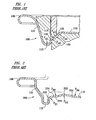
- FIGURE 1 One example of a prior art can lid configuration that employs a structure between the annular countersink and the center panel is depicted in FIGURE 1 .
- the reference numeral 100 generally designates a can lid having a step portion between the annular countersink and the center panel.
- the can lid 100 comprises a peripheral curl portion 108, a chuckwall 114, an annular countersink 112, a center panel 110, a first step portion 116, a transitional portion 118, a second step portion 120, and a third step portion 122.
- negative concavity is relative to concavity in the "downward” direction toward the bottom of the can lid
- positive concavity is relative to concavity in the "upward” direction.
- Can lid 100 is generally circular in shape having the center panel 110, also with a generally circular shape, at the center.
- the peripheral curl 108 portion which is employed to form a double seam with a can body (not shown).
- the chuckwall 114 Immediately adjacent to the peripheral curl portion 108 is the chuckwall 114 that extends radially inward toward the center of the can lid 100 and transitions downward to a lower depth than the peripheral curl portion 108.
- Annular countersink 112 is then formed adjacent to the chuckwall 114 having a radius of curvature r a1 with positive concavity, where the lowest depth of the can lid 100 is located at the apex of the annular countersink 112.
- a transitional portion 118 is employed as the annular countersink 112 transitions from the apex upward, as well as radially inward.
- First step portion 116 with a radius of curvature r a2 with a negative concavity is formed between the annular countersink 112 and the step portion 118.
- Second step portion 120, having a radius of curvature r a3 and positive concavity, and third step portion 122, having a radius of curvature r a4 and negative concavity are utilized to smoothly transition between the depth of the step portion 118 and the center panel 110.
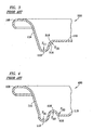
- FIGURE 2 Another example of a prior art can lid configuration that employs a structure between the annular countersink and the center panel is depicted in FIGURE 2 .
- the reference numeral 200 generally designates a can lid having a transitional portion and a raised bead between the annular countersink and the center panel.
- the can lid 200 comprises a peripheral curl portion 108, a chuckwall 114, an annular countersink 112, a center panel 110, a first step portion 216, a transitional portion 214, a second step portion 220, a raised bead 222, and a third step portion 224.
- Can lid 200 is generally circular in shape having the center panel 110, also with a generally circular shape, at the center.
- the peripheral curl 108 portion which is employed to form a double seam with a can body (not shown).
- the chuckwall 114 Immediately adjacent to the peripheral curl portion 108 is the chuckwall 114 that extends radially inward toward the center of the can lid 200 and transitions to a lower depth than the peripheral curl portion 108.
- Annular countersink 112 is then formed adjacent to the chuckwall 114 having a relatively flat bottom parallel to the center panel 110, where the lowest depth of the can lid 200 is located at the bottom portion of the annular countersink 112.
- a transitional portion 214 is employed as the annular countersink 112 transitions from the apex upward, as well as radially inward.
- First step portion 216 with a radius of curvature r b1 with a negative concavity is formed between the annular countersink 112 and the transitional portion 214.
- Transitional portion 214 is at a depth that is approximately equal to center panel 110.
- Second step portion 220, having a radius of curvature r b2 and positive concavity is located between the transitional portion 214 and the raised bead 222, which has a radius of curvature r b3 with negative concavity and a height greater than the center panel 110.
- Third step portion 224, having a radius of curvature r b4 and positive concavity, is utilized to smoothly transition from the raised bead 222 to the center panel 110.
- FIGURE 3 Yet another example of a prior art can lid configuration that employs a structure between the annular countersink and the center panel is depicted in FIGURE 3 .
- the reference numeral 300 generally designates a can lid having a step portion with a bevel between the annular countersink and the center panel.
- the can lid 300 comprises a peripheral curl portion 108, a chuckwall 114, an annular countersink 112, a center panel 110, and a step portion 316.
- Can lid 300 is generally circular in shape having the center panel 110, also with a generally circular shape, at the center.
- the peripheral curl 108 portion which is employed to form a double seam with a can body (not shown).
- the chuckwall 114 Immediately adjacent to the peripheral curl portion 108 is the chuckwall 114 that extends radially inward toward the center of the can lid 300 and transitions to a lower depth than the peripheral curl portion 108.
- Annular countersink 112 is then formed adjacent to the chuckwall 114 having a radius of curvature r c1 with positive concavity relative to the top of the can lid 100, where the lowest depth of the can lid 300 is located at the apex of the annular countersink 112.
- step portion 316 with a radius of curvature r c2 with a negative concavity is formed between the annular countersink 112 and the center panel 110. Additionally, on the outer surface of the step portion 316, a beveled edge 318 is utilized.
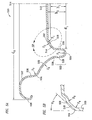
- FIGURE 4 A last example of a prior art can lid configuration that employs a structure between the annular countersink and the center panel is depicted in FIGURE 4 .
- the reference numeral 400 generally designates a can lid having a raised bead between the annular countersink and the center panel.
- the can lid 400 comprises a peripheral curl portion 108, a chuckwall 114, an annular countersink 112, a center panel 110, a raised bead 416, and a step portion 418.
- Can lid 400 is generally circular in shape having the center panel 110, also with a generally circular shape, at the center.
- the peripheral curl 108 portion which is employed to form a double seam with a can body (not shown).
- the chuckwall 114 Immediately adjacent to the peripheral curl portion 108 is the chuckwall 114 that extends radially inward toward the center of the can lid 400 and transitions to a lower depth than the peripheral curl portion 108.
- Annular countersink 112 is then formed adjacent to the chuckwall 114 having a radius of curvature r d1 with positive concavity relative to the top of the can lid 400, where the lowest depth of the can lid 400 is located at the apex of the annular countersink 112.
- Raised bead 416 has a radius of curvature r d2 with a negative concavity where the apex of the raised bead 416 is at a height greater than the center panel 110.
- Transitional portion 418 having a radius of curvature r d3 and positive concavity, couples the raised bead 416 to the center panel 110.
- the present invention provides a lid for a can body.
- the lid comprises a center panel having a central axis that is perpendicular to a diameter of an outer rim of the lid, where the center panel has a height that varies as a function of radial distance relative from the central axis.
- Extending radially outward from the center panel is a first step portion having negative concavity and having a radius of curvature less than about 0,0381 centimeters (0.015 inches).
- a second step portion then, extends radially outward from the first step portion having a positive concavity and having a radius of curvature less than about 0,0381 centimeters (0.015 inches).
- an angled inner wall extends radially outward from the second step portion having an angle from a line extending through each end of the angled inner wall relative to the central axis of less than about 50°.
- an annular countersink portion extends radially outward from the center panel, and a chuckwall extends from the annular countersink.
- a peripheral curl portion extends radially outward from the chuckwall.
- the chuckwall further comprises a number of other features.
- an arcuate portion extends radially outward from the annular countersink and is characterized by a radius of less than about 1,27 centimeters (0.5 inches) with a center point below the surface of the lid, wherein a line passing through the ends of the arcuate portion is at an angle with respect to the central axis of the center panel of from about 20° to about 80°.
- a third step portion extending radially outward from the arcuate portion and characterized by a radius of at least 0,0254 centimeters (0.010 inches), with a center point above the surface of the lid is formed.
- a first transitional portion also extends radially outward from the step portion and being generally frustoconical and inclined at an angle with respect to the central axis of at least about 15° and less than about 25°.
- a second transitional portion extends radially outward from the first transitional portion and is characterized by a radius of at least 0,0508 centimeters (0.020 inches) with a center point below the surface of the lid.
- a line passing through the ends of the angled inner wall is at an angle with respect to the central axis of the center panel from about 25° to about 35° in one embodiment and is about 30° in another embodiment.
- the first step portion has a radius of curvature that is about 0,0254 centimeters (0.010 inches).
- the second step portion has a radius of curvature that is about 0,0254 centimeters (0.010 inches).
- the center panel is substantially domed or arcuate.
- the diameter of the center panel is from about 3,556 to about 5,080 centimeters (about 1.4 to about 2.0 inches), and there is an annular countersink height of from about 0,0762 to about 0,2921 centimeters (about 0.030 to about 0.115 inches).
- the present invention also provides a method of forming a double seam joining a can body to a can lid, the can lid having a center panel having a central axis that is perpendicular to a diameter of an outer rim of the lid, wherein the center panel has a variable height relative to a radial distance relative to the central axis, a first step portion extending radially outward from the center panel, a second step portion extending radially outward from the first step portion, an angled inner wall extending radially outward from the second step portion having an angle from a line extending through each end of the angled inner wall relative to the central axis of less than about 50°, an annular countersink portion extending radially outward from the center panel, a chuckwall having an arcuate step portion and a transitional portion, wherein the chuckwall extends radially outward from the annular countersink, a peripheral curl portion extending radially outward from the chuckwall, and the can body having a
- the method includes or comprises supporting the can body on a base plate and positioning the can lid on the can body with the transitional portion resting on the can body flange. Once positioned, a chuck is provided to engage the can lid with the chuck so as to contact the annular countersink while leaving the arcuate step portion undeformed. The can and lid assembly are then rotated using the chuck to roll the peripheral curl and can body flange together to form an intermediate peripheral seam and to compress the intermediate peripheral seam against the chuck to form a double seam.
- another lid for a can body is provided.
- this lid there is a center panel having a central axis that is the perpendicular to a diameter of an outer rim of the lid.
- Extending radially outward from the center panel portion is an an angled inner wall having an angle from a line extending through each end of the angled inner wall relative to the central axis of less than about 50°.
- extending radially outward from said angled inner wall is an annular countersink portion.
- a chuckwall is also formed, which extends radially outward from the annular countersink. Extending radially outward therefrom is a peripheral curl portion.
- FIGURE 1 depicts an elevational cross-sectional view of a portion of a conventional or prior art can lid having a step portion between the annular countersink and the center panel;
- FIGURE 2 depicts an elevational cross-sectional view of a portion of a conventional or prior art can lid having a step portion and a raised bead between the annular countersink and the center panel;
- FIGURE 3 depicts an elevational cross-sectional view of a portion of a conventional or prior art can lid having a beveled edge in the step portion between the annular countersink and the center panel;
- FIGURE 4 depicts an elevational cross-sectional view of a portion of a conventional or prior art can lid having a raised bead between the annular countersink and the center panel;
- FIGURES 5A and 5B depict elevational cross-sectional views of a portion of a can lid constructed in accordance with the invention
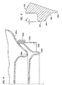
- FIGURE 6 depicts an elevational cross-sectional view of a portion of a can lid according to FIGURE 5 on a can body before the forming of a double seam;
- FIGURE 7 depicts an elevational cross-sectional view of the manner of stacking can lids of FIGURE 5 prior to seaming constructed in accordance with the invention
- FIGURE 8 depicts an elevational cross-sectional view of the manner of stacking filled cans according to FIGURE 5 of the present invention
- FIGURE 9 depicts an elevational cross-sectional view of the chuck used to seam the can lid of FIGURE 5 to the can body.
- FIGURE 10 depicts an elevational cross-sectional view of a second embodiment of the can lid of FIGURE 5 .
- FIGURES 5A and 5B are cross-sectional views of a portion of a can lid 510, illustrative of the currently preferred embodiment of the present invention.
- Can lid 510 comprises a center panel 512, a step portion 552, a step portion 516, an angled inside wall 518, an annular countersink 522, an arcuate portion or arcuate chuckwall 532, a step portion 534, a transitional portion 536, a step portion 537, and a peripheral curl portion 538.
- annular countersink 522 comprises an exterior wall 528, a curved bottom portion 524, and an interior wall 520.
- Can lid 510 is preferably made from sheet metal, although other materials can also be used. Typically, an aluminum alloy is used, such as aluminum alloy 5182.
- the sheet metal typically has a thickness from about 0,01778 to about 0,02540 centimeters (about 0.007 to about 0.010 inches).
- the sheet metal may be coated with a coating (not shown) on at least one side. This coating is usually provided on that side of the sheet metal that will form the interior of the can. Those skilled in the art will be well acquainted with the methods of forming can lids as described herein.
- the can lid 510 has a center panel 512.
- the center panel 512 is generally circular in shape but may be intentionally noncircular.
- the center panel 512 may have a diameter d 1 of from about 3,302 to about 5,080 centimeters (about 1.3 to about 2.0 inches).
- d 1 of from about 3,302 to about 5,080 centimeters (about 1.3 to about 2.0 inches).
- the center panel 512 is shown as being generally peaked or domed, it may also have a generally flat configuration as well, and is not necessarily limited to the peaked or domed configuration shown.
- the center panel 512 has a central axis 514 that is perpendicular to a diameter d 2 of the outer rim, or peripheral curl portion 538, of can lid 510.
- Diameter d 2 is from about 5,715 to 6,350 centimeters (about 2.25 to 2.50 inches) , with a preferred diameter of 5,9436 centimeters (2.34 inches).
- the diameter d 1 of center panel 512 is preferably less than 80% of the diameter d 2 of the outer rim.
- Step portion 552 Around the outside diameter d 1 of the center panel 512 is a step 552 having a radius of curvature r 1 , with a negative concavity that allows transition to a lower depth, that is, from about 0,01524 to about 0,0381 centimeters (about 0.0060 to about 0.015 inches).
- Step portion 516 is adjacent to step portion 552, having a radius of curvature r 2 , with a positive concavity that allows transition to a lower depth, that is, from about 0,0254 to about 0,0381 centimeters (about 0.010 to about 0.015 inches).
- step portion 516 Descending from the bottom of the step portion 516 is an angled inside wall 518, shown in greater detail in FIGURE 5B .
- one end of step portion 516 is attached to a step portion 556 of angled inside wall 518, having a radius of curvature r 3 with negative concavity
- interior wall 520 of annular countersink 522 is attached to a step portion 554 of angled inside wall 518, having a radius of curvature r 4 with negative concavity.
- Angled interior wall 518 is preferably a straight or flat angled interior wall 518; however, it is possible to have an arcuate wall with a negative or positive concavity.
- a straight line can be drawn between the step portion 556 and the step portion 554 (or the ends of wall 518) that forms an acute angle a 1 with respect to central axis 514 of the center panel 512 of about 15° to about 50°.
- the step portion 554 extends radially inward from interior wall 520 toward the remainder of the angled inside wall 518, where the radius of curvature r 4 that is from about 0,01524 to about 0,07620 centimeters (about 0.006 to about 0.03 inches). Additionally, the step portion 556 extends radially inward from the angled inside wall 518, where the radius of curvature r 3 is from about 0,01524 to about 0,07620 centimeters (about 0.006 to about 0.03 inches).
- the angled interior wall 518 can be formed of a surface that includes a pair of curved junctures or step portions with the remainder of the angled interior wall 518 extending linearly and tangentially therebetween; however, it is also possible in an alternative configuration to have a completely arcuate angled inside wall 518 forming a uniform curve or substantially uniform curve.
- the annular countersink 522 is formed from the interior wall 520 and an exterior wall 528, which are spaced apart and extend radially outward from a curved bottom portion 524.
- the inner wall 520 and the outer wall 528 are generally flat and may be parallel to one another and to the central axis 514 but either or both may diverge by an angle of about as much as 15°.
- Bottom portion 524 preferably has a radius of curvature r 5 with positive concavity. Radius of curvature r 4 is from about 0,02286 to about 0,07620 centimeters (about 0.009 to about 0.030 inches).
- the center panel 512 has a depth h 2 of from about 0,1270 to about 0,3810 centimeters (about 0.05 to about 0.15 inches) and may vary.
- the bottom portion 524 of annular countersink 522 may also be formed with different inner and outer radii extending radially outward from a flat portion.
- This particular configuration that includes the formation of the angled inside wall 518, step portion 516, and step portion 552 allows for easier bowing or doming of the center panel 512.
- conventional or prior art can lids typically utilize a center panel, such as center panel 110 of FIGURE 1 , that employs a uniform depth h 1 (shown in FIG. 5 ) of the center panel 512.
- the depth h 2 is variable as a function of the radial distance from the center axis 514, having a generally negative concave shape. This configuration allows for the reduction in the amount of metal used in the lid.
- the use of a negatively concaved center panel 512 increase the internal volume of a can, which in turn reduces internal pressure, so tension can be decreased so as to reduce the probability of premature or unexpected failure of seams within the can lid 510. Additionally, it is also possible, but not preferable, for the center panel 512 to have a positive concave shape.
- the outer wall 528 contains a second chuck contacting portion 550 that is one of two points at which the chuck 544 comes in contact with the interior of the can lid 510 during the seaming operation, the other point being the transitional portion 536.
- An arcuate portion 532 extends radially outward and upward from the outer wall 528.
- the arcuate portion 532 is shown as having a radius of curvature r 6 with negative concavity that is from about 0,2540 to about 0,7620 centimeters (about 0.100 to about 0.300 inches).
- the preferred design parameter for radius of curvature r 6 is 0,01524 to about 0,04699 centimeters (0,006 to about 0.0185 inches).
- the arcuate portion 532 is configured such that a line passing through the innermost end of arcuate portion 532, near the terminus of curved juncture 530, and the outermost end of the arcuate portion 532, near the beginning of step portion 534, forms an acute angle with respect to central axis 514 of the center panel 512. This acute angle is from about 20° to about 80°.
- the preferred lid design uses an angle of about 50°.
- the step portion 534 extends radially outward from the arcuate portion 532.
- Step portion 534 is preferably curved with a radius of curvature r 7 with positive concavity from about 0,0508 to about 0,1524 centimeters (about 0.02 to about 0.06 inches).
- the current lid design parameter for radius of curvature r 7 is 0,11328 centimeters (0.0446 inches).
- First transitional portion 536 extends radially upward and slightly outward from step portion 534.
- First transitional portion 536 forms an angle a 2 with respect to central axis 514 of the center panel 512. This angle is from about 15° to about 25°.
- angle a 2 is intended to be larger than angle a 3 , which is measured relative to central axis 514.
- Angle a 3 is preferably at least about 2° to aid in removing the can from the chuck 544 after the seaming operation and preferably less than about 8°.
- the current design parameter for angle a 3 is about 4°.
- FIGURE 6 shows can lid 510 resting on can body 540, and particularly resting on flange 542 of can body 540.
- the radius r 8 of the can flange 542 is slightly smaller than the step portion 537 radius (not shown). Because the flange radius r 6 and second transitional portion radius are very similar, the lid easily centralizes on the can for seaming.
- the can body has an inside neck diameter d 3 from about 5,21 to about 5,25 centimeters (about 2.051 to about 2.065 inches) , with a target diameter of about 5,23 centimeters (2.058 inches).
- the functional purpose of the chuck 544 in conjunction with can lid 510 is to create a double seam between the can flange 542 and the peripheral curl 538. This is accomplished through the rotation of the chuck 544 so that the peripheral curl 538 can be rolled under the can flange 542 and compressed against the can body 540. Thus, a double seam 554b, as shown in FIGURE 8 , can be formed.
- FIGURE 7 shows the manner in which a plurality of can lids 510a and 510b stack for handling, packaging, and feeding a seaming machine. Underside of peripheral curl 538a bears against upper portion of peripheral curl 538b of adjacent can lid 510b. Can lid 510a is supported and separated from can lid 510b by a height h 3 sufficient to accommodate the thickness of a pull-tab (not shown). In this manner, can lids 510 are compactly and efficiently handled and are more readily positioned for magazine feeding in a mechanized seaming operation.
- FIGURE 8 shows the manner of stacking filled can 564a, closed and sealed according to the present invention on a like filled can 564b. Stand bead 566a rests upon double seam 554b.
- FIGURE 9 shows those portions of the chuck 544 shown in FIGURE 6 , and described above, and also provides a more detailed view of the upper frustoconical portion 546, lower curved portion 580, and the transitional portion 582.
- the upper frustoconical portion 546 and the lower curved portion 580 provide a contact portion for the transitional portion 563 and step portion 534 while the peripheral curl 538 is rolled under the can flange 542 and compressed against the can body 540.
- the transitional portion 582 is designed such that it should not contact the chuckwall 532 during a seaming operation.
- FIG. 10 of the drawings a second embodiment of the present invention of a can lid 510 employing an angled inner wall 518 is depicted. This particular embodiment differs from that of FIG. 5 in that there are not multiple structures interposed between angled inner wall 518 and center panel 512.
- the center panel 512 is generally circular in shape but may be intentionally noncircular.
- the center panel 512 may have a diameter d 1 of from about 3,302 to about 5,080 centimeters (about 1.3 to about 2.0 inches).
- the central axis 514 which is substantially located at the center of can lid 510, is perpendicular to the diameter d 1 of the outer rim of the can lid 510.
- the center panel 512 is shown as having a substantially flat shape with a relatively uniform depth h 1 ; however, it is possible to have a domed or arcuate shape.
- step portion 556 Around the outside diameter d 1 of the center panel 512 is step portion 556 having a radius of curvature r 4 , with a negative concavity that allows transition to a lower depth, which is from about 0,01524 to about 0,0381 centimeters (about 0.0060 to about 0.015 inches). Step portion 556, then, is adjacent to angled inside wall 518. Descending from the bottom of the step portion 556 is angled inside wall 518. Angled interior wall 518 is preferably straight or flat; however, it is possible to have an arcuate wall with a negative or positive concavity. At the end of angled inside wall 518 is step portion 554.
- Step portion 554 is located between angled inside wall 518 and countersink 522, having a radius of curvature r 4 with negative concavity that is from about 0,01524 to about 0,0381 centimeters (about 0.0060 to about 0.015 inches).
- a straight line can, thus, be drawn between the step portion 556 and the step portion 554 (or the ends of wall 518) that forms an acute angle a 1 with respect to central axis 514 of the center panel 512 of about 15° to about 50°.
- this particular configuration would allow for a substantial reduction in the amount of metal used in the production of can lid 510 resulting in a lower cost of production. Additionally, the use of the angled inner wall 518 would help to decrease tension within the center panel 512, which increases the structural integrity of the can lid 510 and which reduces the potential for failure.
Landscapes
- Engineering & Computer Science (AREA)
- Mechanical Engineering (AREA)
- Rigid Containers With Two Or More Constituent Elements (AREA)
- Closures For Containers (AREA)
- Containers Opened By Tearing Frangible Portions (AREA)
Claims (11)
- Couvercle (510) pour corps de boîte comprenant :un panneau central (512) comportant un axe central perpendiculaire à un diamètre d'un rebord extérieur dudit couvercle, dans lequel ledit panneau central a une hauteur variant en fonction de la distance radiale par rapport audit axe central ;une première partie étagée (552) s'étendant dans le sens radial vers l'extérieur à partir dudit panneau central (512) présentant une concavité négative et ayant un rayon de courbure inférieur à 0,0381 centimètres environ (0,015 pouces environ) ;une seconde partie étagée (516) s'étendant dans le sens radial vers l'extérieur à partir de ladite première partie étagée (552) présentant une concavité positive et ayant un rayon de courbure inférieur à 0,0381 centimètres environ (0,015 pouces environ) ;une paroi angulaire intérieure (518) s'étendant dans le sens radial vers l'extérieur à partir de ladite seconde partie étagée (516) faisant un angle, à partir d'une ligne passant par chaque extrémité de ladite paroi angulaire intérieure par rapport audit axe central, inférieur à 50 degrés environ ;une partie de fraisure annulaire (522) s'étendant dans le sens radial vers l'extérieur à partir de ladite paroi angulaire intérieure (518) ;une paroi de serrage (532) s'étendant dans le sens radial vers l'extérieur à partir de ladite fraisure annulaire (522) ; etune partie de courbure périphérique (538) s'étendant dans le sens radial vers l'extérieur à partir de ladite paroi de serrage (532).
- Couvercle selon la revendication 1, dans lequel ladite paroi de serrage (532) comprend en outre :une partie arquée s'étendant dans le sens radial vers l'extérieur à partir de ladite fraisure annulaire (522) et caractérisée par un rayon inférieur à 1,27 centimètres (0,5 pouces), avec un point central en-dessous de la surface du couvercle (510), dans lequel une ligne passant par les extrémités de ladite partie arquée (532) fait un angle avec ledit axe central du panneau central (512) de 20 degrés environ à 80 degrés environ ;une troisième partie étagée (534) s'étendant dans le sens radial vers l'extérieur à partir de ladite partie arquée (532) et caractérisée par un rayon d'au moins 0,0254 centimètres (0,010 pouces), avec un point central au-dessus de la surface du couvercle (510) ;une première partie de transition (536) s'étendant dans le sens radial vers l'extérieur à partir de ladite troisième partie étagée (534) qui est généralement tronconique et inclinée selon un angle d'au moins 15 degrés environ et inférieur à 25 degrés environ, par rapport audit axe central ; etune seconde partie de transition s'étendant dans le sens radial vers l'extérieur à partir de ladite première partie de transition (536) et caractérisée par un rayon d'au moins 0,0508 centimètres (0,020 pouces), avec un point central en-dessous de la surface du couvercle (510).
- Couvercle (510) selon la revendication 1, dans lequel ladite paroi angulaire intérieure (518) comprend en outre une partie étagée (516, 534) à chaque extrémité.
- Couvercle de boîte (510) selon la revendication 1, dans lequel ladite ligne passant par les extrémités de ladite paroi angulaire intérieure (518) fait un angle avec ledit axe central du panneau central (512) de 25 degrés environ à 35 degrés environ.
- Couvercle de boîte (510) selon la revendication 1, dans lequel une ligne passant par les extrémités de ladite paroi angulaire intérieure (518) fait un angle d'environ 30 degrés avec ledit axe central du panneau central (512).
- Couvercle de boîte (510) selon la revendication 1, dans lequel ladite première partie étagée (552) a un rayon de courbure de 0,0254 centimètres environ (0,010 pouces environ).
- Couvercle de boîte (510) selon la revendication 1, dans lequel ladite seconde partie étagée (516) a un rayon de courbure de 0,0254 centimètres environ (0,010 pouces environ).
- Couvercle de boîte (510) selon la revendication 1, dans lequel ledit panneau central (512) est sensiblement bombé ou arqué.
- Couvercle de boîte (510) selon la revendication 1, dans lequel le diamètre dudit panneau central (512) est compris entre 3,556 centimètres environ et 5,08 centimètres environ (entre 1,4 environ et 2,0 pouces environ).
- Couvercle de boîte (510) selon la revendication 1, dans lequel ladite fraisure annulaire (552) a une hauteur comprise entre 0,0762 centimètres environ et 0,2921 centimètres environ (entre 0,030 pouces environ et 0,115 pouces environ).
- Procédé de formation d'un double sertissage reliant un corps de boîte à un couvercle de boîte (510), lequel couvercle de boîte (510) comporte un panneau central ayant un axe central perpendiculaire à un diamètre d'un rebord extérieur dudit couvercle (510), dans lequel ledit panneau central (512) a une hauteur variable par rapport à une distance radiale par rapport audit axe central, une première partie étagée (552) s'étend dans le sens radial vers l'extérieur à partir dudit panneau central (512), une seconde partie étagée (516) s'étend dans le sens radial vers l'extérieur à partir de ladite première partie étagée (552) ; une paroi angulaire intérieure (518) s'étend dans le sens radial vers l'extérieur à partir de ladite seconde partie étagée (516) faisant un angle, à partir d'une ligne passant par chaque extrémité de ladite paroi angulaire intérieure (518) par rapport audit axe central, inférieur à 50 degrés environ ; une partie de fraisure annulaire (522) s'étend dans le sens radial vers l'extérieur à partir dudit panneau central (512), une paroi de serrage (532) présente une partie arquée étagée (534) et une partie de transition (536), dans lequel ladite paroi de serrage (532) s'étend dans le sens radial vers l'extérieur à partir de ladite fraisure annulaire (522), une partie de courbure périphérique (538) s'étend dans le sens radial vers l'extérieur à partir de ladite paroi de serrage (532) et ledit corps de boîte comporte un rebord de corps de boîte, ledit procédé comprenant les étapes suivantes :supporter ledit corps de boîte sur une plaque de base ;positionner ledit couvercle de boîte (510) sur ledit corps de boîte, ladite partie de transition reposant sur ledit rebord du corps de boîte ;prévoir un dispositif de serrage ;mettre en contact ledit couvercle de boîte (510) et ledit dispositif de serrage de manière à venir au contact de ladite fraisure annulaire (522) tout en ne déformant pas ladite partie arquée étagée (534) ;faire tourner ledit ensemble constitué par la boîte et le couvercle (510) en utilisant ledit dispositif de serrage ;faire rouler ladite courbure périphérique (538) et ledit rebord du corps de boîte ensemble pour former un sertissage périphérique intermédiaire ; etcomprimer ledit sertissage périphérique intermédiaire contre ledit dispositif de serrage pour former un double sertissage.
Applications Claiming Priority (2)
| Application Number | Priority Date | Filing Date | Title |
|---|---|---|---|
| US11/188,563 US8490825B2 (en) | 1999-12-08 | 2005-07-25 | Can lid closure and method of joining a can lid closure to a can body |
| PCT/US2006/028824 WO2007014211A1 (fr) | 2005-07-25 | 2006-07-25 | Fermeture de couvercle de boite et procede de jointure d'une fermeture de couvercle de boite a un corps de boite |
Publications (3)
| Publication Number | Publication Date |
|---|---|
| EP1907287A1 EP1907287A1 (fr) | 2008-04-09 |
| EP1907287A4 EP1907287A4 (fr) | 2009-08-12 |
| EP1907287B1 true EP1907287B1 (fr) | 2010-05-05 |
Family
ID=37683682
Family Applications (1)
| Application Number | Title | Priority Date | Filing Date |
|---|---|---|---|
| EP06788417A Not-in-force EP1907287B1 (fr) | 2005-07-25 | 2006-07-25 | Fermeture de couvercle de boite et procede de jointure d'une fermeture de couvercle de boite a un corps de boite |
Country Status (12)
| Country | Link |
|---|---|
| US (1) | US8490825B2 (fr) |
| EP (1) | EP1907287B1 (fr) |
| JP (1) | JP2009502677A (fr) |
| CN (1) | CN101267991B (fr) |
| AT (1) | ATE466780T1 (fr) |
| AU (1) | AU2006272664B2 (fr) |
| BR (1) | BRPI0613898A2 (fr) |
| CA (1) | CA2615779C (fr) |
| DE (1) | DE602006014157D1 (fr) |
| ES (1) | ES2344470T3 (fr) |
| MX (1) | MX2008001101A (fr) |
| WO (1) | WO2007014211A1 (fr) |
Families Citing this family (28)
| Publication number | Priority date | Publication date | Assignee | Title |
|---|---|---|---|---|
| US6419110B1 (en) | 2001-07-03 | 2002-07-16 | Container Development, Ltd. | Double-seamed can end and method for forming |
| DE602005023470D1 (de) | 2004-07-29 | 2010-10-21 | Ball Corp | Verfahren und vorrichtung zur formung des endverschlusses eines metallbehälters |
| WO2006036934A2 (fr) * | 2004-09-27 | 2006-04-06 | Ball Corporation | Fermeture d'extremite de contenant a paroi de retenue et fraisure ameliorees |
| US7506779B2 (en) | 2005-07-01 | 2009-03-24 | Ball Corporation | Method and apparatus for forming a reinforcing bead in a container end closure |
| US8875936B2 (en) * | 2007-04-20 | 2014-11-04 | Rexam Beverage Can Company | Can end with negatively angled wall |
| US8011527B2 (en) * | 2007-08-10 | 2011-09-06 | Rexam Beverage Can Company | Can end with countersink |
| US8973780B2 (en) | 2007-08-10 | 2015-03-10 | Rexam Beverage Can Company | Can end with reinforcing bead |
| JP5468278B2 (ja) * | 2009-03-17 | 2014-04-09 | ユニバーサル製缶株式会社 | 缶蓋 |
| WO2011041304A2 (fr) | 2009-09-29 | 2011-04-07 | Board Of Regents, University Of Texas System | Agents antipaludiques inhibiteurs de la dihydro-orotate déshydrogénase |
| US8727169B2 (en) | 2010-11-18 | 2014-05-20 | Ball Corporation | Metallic beverage can end closure with offset countersink |
| US8939695B2 (en) | 2011-06-16 | 2015-01-27 | Sonoco Development, Inc. | Method for applying a metal end to a container body |
| US8998027B2 (en) | 2011-09-02 | 2015-04-07 | Sonoco Development, Inc. | Retort container with thermally fused double-seamed or crimp-seamed metal end |
| US10131455B2 (en) | 2011-10-28 | 2018-11-20 | Sonoco Development, Inc. | Apparatus and method for induction sealing of conveyed workpieces |
| US10399139B2 (en) | 2012-04-12 | 2019-09-03 | Sonoco Development, Inc. | Method of making a retort container |
| US9821928B2 (en) | 2012-05-14 | 2017-11-21 | Rexam Beverage Can Company | Can end |
| JP2014019479A (ja) * | 2012-07-19 | 2014-02-03 | Daiwa Can Co Ltd | 缶蓋 |
| JP6320398B2 (ja) | 2012-10-18 | 2018-05-09 | ストール マシーナリ カンパニー, エルエルシーStolle Machinery Company, LLC | 圧印加工されたパネルアール部を有するエンドクロージャ及びリフォーム工程 |
| GB201306765D0 (en) * | 2013-04-12 | 2013-05-29 | Crown Packaging Technology Inc | Method and apparatus for manufacturing a can end |
| MY174736A (en) * | 2013-05-31 | 2020-05-12 | Crown Packaging Technology Inc | Beverage can end having an arcuate panel wall and curved transition wall |
| JP2018020334A (ja) * | 2016-08-02 | 2018-02-08 | ユニバーサル製缶株式会社 | 缶蓋、これを用いた缶の巻締め部構造及び缶蓋の巻締め方法 |
| JP6347337B1 (ja) * | 2016-12-22 | 2018-06-27 | 東洋製罐株式会社 | 金属製ボトルの製造方法 |
| US10518926B2 (en) | 2017-08-30 | 2019-12-31 | Stolle Machinery Company, Llc | Reverse pressure can end |
| US10947002B2 (en) * | 2017-08-30 | 2021-03-16 | Stolle Machinery Company, Llc | Reverse pressure can end |
| US10894630B2 (en) | 2017-08-30 | 2021-01-19 | Stolle Machinery Company, Llc | Pressure can end compatible with standard can seamer |
| CN108438434B (zh) * | 2018-04-16 | 2023-12-15 | 苏州斯莱克精密设备股份有限公司 | 一种耐压基本盖、易拉盖以及带易拉盖的易拉罐 |
| CN113993640B (zh) * | 2019-06-13 | 2023-11-17 | 斯多里机械有限责任公司 | 反向压力罐端部 |
| WO2022170343A1 (fr) * | 2021-02-05 | 2022-08-11 | Novelis, Inc. | Extrémité de récipient métallique à bord périphérique matricé et procédés associés |
| US12071280B2 (en) * | 2022-01-05 | 2024-08-27 | Ball Corporation | Metallic end closure for small diameter container |
Family Cites Families (62)
| Publication number | Priority date | Publication date | Assignee | Title |
|---|---|---|---|---|
| US3774801A (en) | 1971-02-22 | 1973-11-27 | American Can Co | Reinforced metal can end |
| US3749277A (en) | 1971-11-01 | 1973-07-31 | Phillips Petroleum Co | Closure having improved resistance to unseating |
| LU66736A1 (fr) | 1972-12-21 | 1974-07-10 | ||
| JPS5429952B2 (fr) | 1974-05-09 | 1979-09-27 | ||
| JPS5474184A (en) | 1977-11-25 | 1979-06-14 | Toyo Seikan Kaisha Ltd | Can lid lockkseaming tool |
| GB1602309A (en) | 1978-05-30 | 1981-11-11 | Metal Box Co Ltd | Containers |
| US4448322A (en) | 1978-12-08 | 1984-05-15 | National Can Corporation | Metal container end |
| JPS6239866Y2 (fr) | 1979-02-22 | 1987-10-12 | ||
| JPS5653836A (en) | 1980-08-29 | 1981-05-13 | Toyo Seikan Kaisha Ltd | Can cap seaming tool |
| JPS5653835A (en) | 1980-08-29 | 1981-05-13 | Toyo Seikan Kaisha Ltd | Can cap seaming tool |
| JPS5744435A (en) | 1980-08-29 | 1982-03-12 | Toyo Seikan Kaisha Ltd | Can lid winding and fastening tool |
| JPS5794436A (en) | 1980-12-03 | 1982-06-11 | Toyo Seikan Kaisha Ltd | Seaming chuck |
| JPS5835028A (ja) | 1981-08-24 | 1983-03-01 | Kishimoto Akira | 2重巻締部の形成方法および工具 |
| JPS5835029A (ja) | 1981-08-24 | 1983-03-01 | Kishimoto Akira | 2重巻締部の形成方法 |
| JPS5870329A (ja) | 1981-10-20 | 1983-04-26 | Mitsubishi Electric Corp | 電力量制御回路 |
| USRE33217E (en) | 1982-03-11 | 1990-05-15 | Ball Corporation | Buckle resistance for metal container closures |
| US4577774A (en) | 1982-03-11 | 1986-03-25 | Ball Corporation | Buckle resistance for metal container closures |
| EP0103074A3 (fr) | 1982-09-09 | 1984-05-23 | Ball Corporation | Obtention d'une rigidité élevée de couvercles métalliques par retournement de segments courbés |
| JPS59144535A (ja) | 1983-02-03 | 1984-08-18 | Kyocera Corp | 缶蓋巻締用工具 |
| JPS6123533A (ja) | 1984-07-11 | 1986-02-01 | Hokkai Can Co Ltd | ネックイン加工缶の製造法 |
| JPS63125152A (ja) | 1986-11-12 | 1988-05-28 | 東洋製罐株式会社 | イ−ジイオ−プン蓋 |
| US4832223A (en) | 1987-07-20 | 1989-05-23 | Ball Corporation | Container closure with increased strength |
| US4796772A (en) | 1987-09-07 | 1989-01-10 | Ball Corporation | Metal closure with circumferentially-variegated strengthening |
| JP2642110B2 (ja) * | 1987-12-23 | 1997-08-20 | 北海製罐株式会社 | 二重巻締用缶蓋及びその製造方法 |
| JPH0798232B2 (ja) | 1987-12-25 | 1995-10-25 | 大和製罐株式会社 | 缶蓋巻締め法 |
| GB8810229D0 (en) | 1988-04-29 | 1988-06-02 | Metal Box Plc | Can end shells |
| JPH01289526A (ja) | 1988-05-17 | 1989-11-21 | Toyo Seikan Kaisha Ltd | 缶蓋の巻締方法 |
| JPH0292426A (ja) | 1988-09-29 | 1990-04-03 | Toppan Printing Co Ltd | ポリエステル製缶の製造方法 |
| JP2544222Y2 (ja) | 1989-04-06 | 1997-08-13 | 東洋製罐株式会社 | 耐圧容器用端壁 |
| US4991735A (en) | 1989-05-08 | 1991-02-12 | Aluminum Company Of America | Pressure resistant end shell for a container and method and apparatus for forming the same |
| JPH0332835A (ja) | 1989-11-10 | 1991-02-13 | Toyo Seikan Kaisha Ltd | 絞りしごき罐 |
| JPH03275443A (ja) | 1990-03-10 | 1991-12-06 | Toyo Seikan Kaisha Ltd | 耐圧缶用蓋の製造方法および耐圧缶用蓋 |
| JP2846928B2 (ja) | 1990-06-25 | 1999-01-13 | 北海製罐株式会社 | 缶蓋の巻締方法 |
| US5149238A (en) | 1991-01-30 | 1992-09-22 | The Stolle Corporation | Pressure resistant sheet metal end closure |
| JP3400804B2 (ja) | 1991-08-29 | 2003-04-28 | 北海製罐株式会社 | 缶蓋の巻締方法及びその装置 |
| GB9204972D0 (en) | 1992-03-06 | 1992-04-22 | Cmb Foodcan Plc | Laminated metal sheet |
| US5253781A (en) | 1992-06-29 | 1993-10-19 | James River Corporation Of Virginia | Disposable drink-through cup lid |
| JP2570560B2 (ja) | 1992-12-08 | 1997-01-08 | 東洋製罐株式会社 | 容易開口罐蓋 |
| GB2315478B (en) | 1994-07-20 | 1998-12-23 | Metal Box Plc | Containers |
| JP2777546B2 (ja) | 1994-12-19 | 1998-07-16 | 東洋食品機械株式会社 | 缶の二重巻締め機 |
| JP3581183B2 (ja) | 1995-01-12 | 2004-10-27 | 三菱マテリアル株式会社 | 缶蓋 |
| GB9510515D0 (en) | 1995-05-24 | 1995-07-19 | Metal Box Plc | Containers |
| GB9702475D0 (en) | 1997-02-07 | 1997-03-26 | Metal Box Plc | Can ends |
| US5975344A (en) | 1998-03-17 | 1999-11-02 | Letica Corporation | Closure having controlled radial flex |
| DE29906170U1 (de) | 1998-04-12 | 1999-09-23 | Schmalbach-Lubeca AG, 40880 Ratingen | Verschlußdeckel mit stapelfähigem Seitenspiel |
| US6102243A (en) | 1998-08-26 | 2000-08-15 | Crown Cork & Seal Technologies Corporation | Can end having a strengthened side wall and apparatus and method of making same |
| JP3784550B2 (ja) | 1998-09-30 | 2006-06-14 | 大和製罐株式会社 | 正内圧缶用缶蓋 |
| EP1470052B1 (fr) | 1999-12-08 | 2012-09-19 | Ball Corporation | Extrémité de canette de boisson métallique avec paroi d'appui et rainure améliorées |
| US6499622B1 (en) | 1999-12-08 | 2002-12-31 | Metal Container Corporation, Inc. | Can lid closure and method of joining a can lid closure to a can body |
| US6561004B1 (en) * | 1999-12-08 | 2003-05-13 | Metal Container Corporation | Can lid closure and method of joining a can lid closure to a can body |
| JP2002178072A (ja) | 2000-12-13 | 2002-06-25 | Daiwa Can Co Ltd | 缶 蓋 |
| US6460723B2 (en) | 2001-01-19 | 2002-10-08 | Ball Corporation | Metallic beverage can end |
| JP4666330B2 (ja) | 2001-04-19 | 2011-04-06 | 大和製罐株式会社 | 正内圧缶用の缶蓋 |
| US6419110B1 (en) | 2001-07-03 | 2002-07-16 | Container Development, Ltd. | Double-seamed can end and method for forming |
| US7819275B2 (en) * | 2001-07-03 | 2010-10-26 | Container Development, Ltd. | Can shell and double-seamed can end |
| US7004345B2 (en) * | 2001-08-16 | 2006-02-28 | Rexam Beverage Can Company | Can end |
| US6748789B2 (en) | 2001-10-19 | 2004-06-15 | Rexam Beverage Can Company | Reformed can end for a container and method for producing same |
| JP4003435B2 (ja) | 2001-10-31 | 2007-11-07 | 東洋製罐株式会社 | 缶蓋 |
| JP4388726B2 (ja) | 2002-01-15 | 2009-12-24 | 東洋製罐株式会社 | 缶蓋 |
| US6932234B2 (en) | 2002-05-29 | 2005-08-23 | Seda S.P.A. | Cup-shaped receptacle and lid |
| HRP20041195B1 (en) * | 2002-05-29 | 2012-06-30 | Seda S.P.A. | Cup-shaped receptacle and lid |
| JP4263551B2 (ja) * | 2003-08-07 | 2009-05-13 | ユニバーサル製缶株式会社 | 缶蓋成形用金型装置 |
-
2005
- 2005-07-25 US US11/188,563 patent/US8490825B2/en not_active Expired - Fee Related
-
2006
- 2006-07-25 CA CA2615779A patent/CA2615779C/fr not_active Expired - Fee Related
- 2006-07-25 EP EP06788417A patent/EP1907287B1/fr not_active Not-in-force
- 2006-07-25 MX MX2008001101A patent/MX2008001101A/es active IP Right Grant
- 2006-07-25 JP JP2008524062A patent/JP2009502677A/ja active Pending
- 2006-07-25 AT AT06788417T patent/ATE466780T1/de not_active IP Right Cessation
- 2006-07-25 BR BRPI0613898-5A patent/BRPI0613898A2/pt not_active Application Discontinuation
- 2006-07-25 DE DE602006014157T patent/DE602006014157D1/de active Active
- 2006-07-25 CN CN2006800344417A patent/CN101267991B/zh not_active Expired - Fee Related
- 2006-07-25 AU AU2006272664A patent/AU2006272664B2/en not_active Ceased
- 2006-07-25 WO PCT/US2006/028824 patent/WO2007014211A1/fr not_active Ceased
- 2006-07-25 ES ES06788417T patent/ES2344470T3/es active Active
Also Published As
| Publication number | Publication date |
|---|---|
| DE602006014157D1 (de) | 2010-06-17 |
| CA2615779A1 (fr) | 2007-02-01 |
| ES2344470T3 (es) | 2010-08-27 |
| EP1907287A4 (fr) | 2009-08-12 |
| MX2008001101A (es) | 2008-03-11 |
| HK1124575A1 (en) | 2009-07-17 |
| JP2009502677A (ja) | 2009-01-29 |
| US20050252922A1 (en) | 2005-11-17 |
| CA2615779C (fr) | 2014-04-22 |
| AU2006272664A1 (en) | 2007-02-01 |
| WO2007014211A1 (fr) | 2007-02-01 |
| BRPI0613898A2 (pt) | 2012-12-18 |
| ATE466780T1 (de) | 2010-05-15 |
| US8490825B2 (en) | 2013-07-23 |
| CN101267991B (zh) | 2011-02-02 |
| AU2006272664B2 (en) | 2012-09-06 |
| CN101267991A (zh) | 2008-09-17 |
| EP1907287A1 (fr) | 2008-04-09 |
Similar Documents
| Publication | Publication Date | Title |
|---|---|---|
| EP1907287B1 (fr) | Fermeture de couvercle de boite et procede de jointure d'une fermeture de couvercle de boite a un corps de boite | |
| US6499622B1 (en) | Can lid closure and method of joining a can lid closure to a can body | |
| US6561004B1 (en) | Can lid closure and method of joining a can lid closure to a can body | |
| US7380684B2 (en) | Can lid closure | |
| AU2002231236A1 (en) | Can lid closure and method of joining a can lid closure to a can body | |
| AU2002354810A1 (en) | Can shell and double-seamed can end | |
| WO2003004716A2 (fr) | Enveloppe de canette et extremite de canette a sertissage double | |
| JP7206046B2 (ja) | ボトル缶およびボトル缶の製造方法 | |
| HK1124575B (en) | Can lid closure and method of joining a can lid closure to a can body | |
| HK1093938B (en) | A method of forming a double seam joining a can body to a can lid | |
| HK1056137B (en) | Can lid closure |
Legal Events
| Date | Code | Title | Description |
|---|---|---|---|
| PUAI | Public reference made under article 153(3) epc to a published international application that has entered the european phase |
Free format text: ORIGINAL CODE: 0009012 |
|
| 17P | Request for examination filed |
Effective date: 20080123 |
|
| AK | Designated contracting states |
Kind code of ref document: A1 Designated state(s): AT BE BG CH CY CZ DE DK EE ES FI FR GB GR HU IE IS IT LI LT LU LV MC NL PL PT RO SE SI SK TR |
|
| A4 | Supplementary search report drawn up and despatched |
Effective date: 20090710 |
|
| RIC1 | Information provided on ipc code assigned before grant |
Ipc: B21D 51/32 20060101ALI20090706BHEP Ipc: B21D 51/30 20060101ALI20090706BHEP Ipc: B65D 1/12 20060101ALI20090706BHEP Ipc: B65D 17/00 20060101AFI20070328BHEP Ipc: B21D 51/26 20060101ALI20090706BHEP |
|
| GRAP | Despatch of communication of intention to grant a patent |
Free format text: ORIGINAL CODE: EPIDOSNIGR1 |
|
| RIN1 | Information on inventor provided before grant (corrected) |
Inventor name: REED, JAMES Inventor name: NEINER, CHRISTOPHER |
|
| GRAS | Grant fee paid |
Free format text: ORIGINAL CODE: EPIDOSNIGR3 |
|
| GRAA | (expected) grant |
Free format text: ORIGINAL CODE: 0009210 |
|
| AK | Designated contracting states |
Kind code of ref document: B1 Designated state(s): AT BE BG CH CY CZ DE DK EE ES FI FR GB GR HU IE IS IT LI LT LU LV MC NL PL PT RO SE SI SK TR |
|
| REG | Reference to a national code |
Ref country code: GB Ref legal event code: FG4D |
|
| REG | Reference to a national code |
Ref country code: CH Ref legal event code: EP |
|
| REG | Reference to a national code |
Ref country code: IE Ref legal event code: FG4D |
|
| REF | Corresponds to: |
Ref document number: 602006014157 Country of ref document: DE Date of ref document: 20100617 Kind code of ref document: P |
|
| REG | Reference to a national code |
Ref country code: NL Ref legal event code: VDEP Effective date: 20100505 |
|
| REG | Reference to a national code |
Ref country code: ES Ref legal event code: FG2A Ref document number: 2344470 Country of ref document: ES Kind code of ref document: T3 |
|
| LTIE | Lt: invalidation of european patent or patent extension |
Effective date: 20100505 |
|
| PG25 | Lapsed in a contracting state [announced via postgrant information from national office to epo] |
Ref country code: NL Free format text: LAPSE BECAUSE OF FAILURE TO SUBMIT A TRANSLATION OF THE DESCRIPTION OR TO PAY THE FEE WITHIN THE PRESCRIBED TIME-LIMIT Effective date: 20100505 Ref country code: SE Free format text: LAPSE BECAUSE OF FAILURE TO SUBMIT A TRANSLATION OF THE DESCRIPTION OR TO PAY THE FEE WITHIN THE PRESCRIBED TIME-LIMIT Effective date: 20100505 Ref country code: LT Free format text: LAPSE BECAUSE OF FAILURE TO SUBMIT A TRANSLATION OF THE DESCRIPTION OR TO PAY THE FEE WITHIN THE PRESCRIBED TIME-LIMIT Effective date: 20100505 |
|
| PG25 | Lapsed in a contracting state [announced via postgrant information from national office to epo] |
Ref country code: LV Free format text: LAPSE BECAUSE OF FAILURE TO SUBMIT A TRANSLATION OF THE DESCRIPTION OR TO PAY THE FEE WITHIN THE PRESCRIBED TIME-LIMIT Effective date: 20100505 Ref country code: IS Free format text: LAPSE BECAUSE OF FAILURE TO SUBMIT A TRANSLATION OF THE DESCRIPTION OR TO PAY THE FEE WITHIN THE PRESCRIBED TIME-LIMIT Effective date: 20100905 Ref country code: SI Free format text: LAPSE BECAUSE OF FAILURE TO SUBMIT A TRANSLATION OF THE DESCRIPTION OR TO PAY THE FEE WITHIN THE PRESCRIBED TIME-LIMIT Effective date: 20100505 Ref country code: AT Free format text: LAPSE BECAUSE OF FAILURE TO SUBMIT A TRANSLATION OF THE DESCRIPTION OR TO PAY THE FEE WITHIN THE PRESCRIBED TIME-LIMIT Effective date: 20100505 Ref country code: FI Free format text: LAPSE BECAUSE OF FAILURE TO SUBMIT A TRANSLATION OF THE DESCRIPTION OR TO PAY THE FEE WITHIN THE PRESCRIBED TIME-LIMIT Effective date: 20100505 |
|
| PG25 | Lapsed in a contracting state [announced via postgrant information from national office to epo] |
Ref country code: PL Free format text: LAPSE BECAUSE OF FAILURE TO SUBMIT A TRANSLATION OF THE DESCRIPTION OR TO PAY THE FEE WITHIN THE PRESCRIBED TIME-LIMIT Effective date: 20100505 Ref country code: CY Free format text: LAPSE BECAUSE OF FAILURE TO SUBMIT A TRANSLATION OF THE DESCRIPTION OR TO PAY THE FEE WITHIN THE PRESCRIBED TIME-LIMIT Effective date: 20100526 Ref country code: GR Free format text: LAPSE BECAUSE OF FAILURE TO SUBMIT A TRANSLATION OF THE DESCRIPTION OR TO PAY THE FEE WITHIN THE PRESCRIBED TIME-LIMIT Effective date: 20100806 |
|
| PG25 | Lapsed in a contracting state [announced via postgrant information from national office to epo] |
Ref country code: EE Free format text: LAPSE BECAUSE OF FAILURE TO SUBMIT A TRANSLATION OF THE DESCRIPTION OR TO PAY THE FEE WITHIN THE PRESCRIBED TIME-LIMIT Effective date: 20100505 Ref country code: DK Free format text: LAPSE BECAUSE OF FAILURE TO SUBMIT A TRANSLATION OF THE DESCRIPTION OR TO PAY THE FEE WITHIN THE PRESCRIBED TIME-LIMIT Effective date: 20100505 Ref country code: PT Free format text: LAPSE BECAUSE OF FAILURE TO SUBMIT A TRANSLATION OF THE DESCRIPTION OR TO PAY THE FEE WITHIN THE PRESCRIBED TIME-LIMIT Effective date: 20100906 |
|
| PG25 | Lapsed in a contracting state [announced via postgrant information from national office to epo] |
Ref country code: BE Free format text: LAPSE BECAUSE OF FAILURE TO SUBMIT A TRANSLATION OF THE DESCRIPTION OR TO PAY THE FEE WITHIN THE PRESCRIBED TIME-LIMIT Effective date: 20100505 Ref country code: CZ Free format text: LAPSE BECAUSE OF FAILURE TO SUBMIT A TRANSLATION OF THE DESCRIPTION OR TO PAY THE FEE WITHIN THE PRESCRIBED TIME-LIMIT Effective date: 20100505 Ref country code: MC Free format text: LAPSE BECAUSE OF NON-PAYMENT OF DUE FEES Effective date: 20100731 Ref country code: RO Free format text: LAPSE BECAUSE OF FAILURE TO SUBMIT A TRANSLATION OF THE DESCRIPTION OR TO PAY THE FEE WITHIN THE PRESCRIBED TIME-LIMIT Effective date: 20100505 Ref country code: SK Free format text: LAPSE BECAUSE OF FAILURE TO SUBMIT A TRANSLATION OF THE DESCRIPTION OR TO PAY THE FEE WITHIN THE PRESCRIBED TIME-LIMIT Effective date: 20100505 |
|
| REG | Reference to a national code |
Ref country code: CH Ref legal event code: PL |
|
| PLBE | No opposition filed within time limit |
Free format text: ORIGINAL CODE: 0009261 |
|
| STAA | Information on the status of an ep patent application or granted ep patent |
Free format text: STATUS: NO OPPOSITION FILED WITHIN TIME LIMIT |
|
| 26N | No opposition filed |
Effective date: 20110208 |
|
| PG25 | Lapsed in a contracting state [announced via postgrant information from national office to epo] |
Ref country code: CH Free format text: LAPSE BECAUSE OF NON-PAYMENT OF DUE FEES Effective date: 20100731 Ref country code: LI Free format text: LAPSE BECAUSE OF NON-PAYMENT OF DUE FEES Effective date: 20100731 |
|
| REG | Reference to a national code |
Ref country code: DE Ref legal event code: R097 Ref document number: 602006014157 Country of ref document: DE Effective date: 20110207 |
|
| PG25 | Lapsed in a contracting state [announced via postgrant information from national office to epo] |
Ref country code: LU Free format text: LAPSE BECAUSE OF NON-PAYMENT OF DUE FEES Effective date: 20100725 Ref country code: HU Free format text: LAPSE BECAUSE OF FAILURE TO SUBMIT A TRANSLATION OF THE DESCRIPTION OR TO PAY THE FEE WITHIN THE PRESCRIBED TIME-LIMIT Effective date: 20101106 Ref country code: BG Free format text: LAPSE BECAUSE OF FAILURE TO SUBMIT A TRANSLATION OF THE DESCRIPTION OR TO PAY THE FEE WITHIN THE PRESCRIBED TIME-LIMIT Effective date: 20100505 |
|
| PG25 | Lapsed in a contracting state [announced via postgrant information from national office to epo] |
Ref country code: TR Free format text: LAPSE BECAUSE OF FAILURE TO SUBMIT A TRANSLATION OF THE DESCRIPTION OR TO PAY THE FEE WITHIN THE PRESCRIBED TIME-LIMIT Effective date: 20100505 |
|
| PG25 | Lapsed in a contracting state [announced via postgrant information from national office to epo] |
Ref country code: BG Free format text: LAPSE BECAUSE OF FAILURE TO SUBMIT A TRANSLATION OF THE DESCRIPTION OR TO PAY THE FEE WITHIN THE PRESCRIBED TIME-LIMIT Effective date: 20100805 |
|
| REG | Reference to a national code |
Ref country code: FR Ref legal event code: PLFP Year of fee payment: 11 |
|
| REG | Reference to a national code |
Ref country code: FR Ref legal event code: PLFP Year of fee payment: 12 |
|
| PGFP | Annual fee paid to national office [announced via postgrant information from national office to epo] |
Ref country code: FR Payment date: 20170613 Year of fee payment: 12 |
|
| PGFP | Annual fee paid to national office [announced via postgrant information from national office to epo] |
Ref country code: ES Payment date: 20170801 Year of fee payment: 12 Ref country code: DE Payment date: 20170719 Year of fee payment: 12 Ref country code: GB Payment date: 20170719 Year of fee payment: 12 Ref country code: IT Payment date: 20170720 Year of fee payment: 12 |
|
| PGFP | Annual fee paid to national office [announced via postgrant information from national office to epo] |
Ref country code: IE Payment date: 20170710 Year of fee payment: 12 |
|
| REG | Reference to a national code |
Ref country code: DE Ref legal event code: R119 Ref document number: 602006014157 Country of ref document: DE |
|
| GBPC | Gb: european patent ceased through non-payment of renewal fee |
Effective date: 20180725 |
|
| REG | Reference to a national code |
Ref country code: IE Ref legal event code: MM4A |
|
| PG25 | Lapsed in a contracting state [announced via postgrant information from national office to epo] |
Ref country code: GB Free format text: LAPSE BECAUSE OF NON-PAYMENT OF DUE FEES Effective date: 20180725 Ref country code: FR Free format text: LAPSE BECAUSE OF NON-PAYMENT OF DUE FEES Effective date: 20180731 Ref country code: IE Free format text: LAPSE BECAUSE OF NON-PAYMENT OF DUE FEES Effective date: 20180725 Ref country code: DE Free format text: LAPSE BECAUSE OF NON-PAYMENT OF DUE FEES Effective date: 20190201 |
|
| PG25 | Lapsed in a contracting state [announced via postgrant information from national office to epo] |
Ref country code: IT Free format text: LAPSE BECAUSE OF NON-PAYMENT OF DUE FEES Effective date: 20180725 |
|
| REG | Reference to a national code |
Ref country code: ES Ref legal event code: FD2A Effective date: 20190917 |
|
| PG25 | Lapsed in a contracting state [announced via postgrant information from national office to epo] |
Ref country code: ES Free format text: LAPSE BECAUSE OF NON-PAYMENT OF DUE FEES Effective date: 20180726 |