EP1909368B1 - Agencement de commutation et procédé de surveillance d'isolation pour des applications de convertisseur - Google Patents
Agencement de commutation et procédé de surveillance d'isolation pour des applications de convertisseur Download PDFInfo
- Publication number
- EP1909368B1 EP1909368B1 EP07405298.6A EP07405298A EP1909368B1 EP 1909368 B1 EP1909368 B1 EP 1909368B1 EP 07405298 A EP07405298 A EP 07405298A EP 1909368 B1 EP1909368 B1 EP 1909368B1
- Authority
- EP
- European Patent Office
- Prior art keywords
- voltage
- branch
- inverter
- phase connections
- insulation
- Prior art date
- Legal status (The legal status is an assumption and is not a legal conclusion. Google has not performed a legal analysis and makes no representation as to the accuracy of the status listed.)
- Ceased
Links
Images


Classifications
-
- H—ELECTRICITY
- H02—GENERATION; CONVERSION OR DISTRIBUTION OF ELECTRIC POWER
- H02H—EMERGENCY PROTECTIVE CIRCUIT ARRANGEMENTS
- H02H7/00—Emergency protective circuit arrangements specially adapted for specific types of electric machines or apparatus or for sectionalised protection of cable or line systems, and effecting automatic switching in the event of an undesired change from normal working conditions
- H02H7/10—Emergency protective circuit arrangements specially adapted for specific types of electric machines or apparatus or for sectionalised protection of cable or line systems, and effecting automatic switching in the event of an undesired change from normal working conditions for converters; for rectifiers
- H02H7/12—Emergency protective circuit arrangements specially adapted for specific types of electric machines or apparatus or for sectionalised protection of cable or line systems, and effecting automatic switching in the event of an undesired change from normal working conditions for converters; for rectifiers for static converters or rectifiers
- H02H7/122—Emergency protective circuit arrangements specially adapted for specific types of electric machines or apparatus or for sectionalised protection of cable or line systems, and effecting automatic switching in the event of an undesired change from normal working conditions for converters; for rectifiers for static converters or rectifiers for inverters, i.e. DC/AC converters
- H02H7/1227—Emergency protective circuit arrangements specially adapted for specific types of electric machines or apparatus or for sectionalised protection of cable or line systems, and effecting automatic switching in the event of an undesired change from normal working conditions for converters; for rectifiers for static converters or rectifiers for inverters, i.e. DC/AC converters responsive to abnormalities in the output circuit, e.g. short circuit
-
- G—PHYSICS
- G01—MEASURING; TESTING
- G01R—MEASURING ELECTRIC VARIABLES; MEASURING MAGNETIC VARIABLES
- G01R27/00—Arrangements for measuring resistance, reactance, impedance, or electric characteristics derived therefrom
- G01R27/02—Measuring real or complex resistance, reactance, impedance, or other two-pole characteristics derived therefrom, e.g. time constant
- G01R27/16—Measuring impedance of element or network through which a current is passing from another source, e.g. cable, power line
- G01R27/18—Measuring resistance to earth, i.e. line to ground
-
- G—PHYSICS
- G01—MEASURING; TESTING
- G01R—MEASURING ELECTRIC VARIABLES; MEASURING MAGNETIC VARIABLES
- G01R31/00—Arrangements for testing electric properties; Arrangements for locating electric faults; Arrangements for electrical testing characterised by what is being tested not provided for elsewhere
- G01R31/50—Testing of electric apparatus, lines, cables or components for short-circuits, continuity, leakage current or incorrect line connections
- G01R31/52—Testing for short-circuits, leakage current or ground faults
-
- G—PHYSICS
- G01—MEASURING; TESTING
- G01R—MEASURING ELECTRIC VARIABLES; MEASURING MAGNETIC VARIABLES
- G01R31/00—Arrangements for testing electric properties; Arrangements for locating electric faults; Arrangements for electrical testing characterised by what is being tested not provided for elsewhere
- G01R31/12—Testing dielectric strength or breakdown voltage ; Testing or monitoring effectiveness or level of insulation, e.g. of a cable or of an apparatus, for example using partial discharge measurements; Electrostatic testing
- G01R31/1227—Testing dielectric strength or breakdown voltage ; Testing or monitoring effectiveness or level of insulation, e.g. of a cable or of an apparatus, for example using partial discharge measurements; Electrostatic testing of components, parts or materials
-
- G—PHYSICS
- G01—MEASURING; TESTING
- G01R—MEASURING ELECTRIC VARIABLES; MEASURING MAGNETIC VARIABLES
- G01R31/00—Arrangements for testing electric properties; Arrangements for locating electric faults; Arrangements for electrical testing characterised by what is being tested not provided for elsewhere
- G01R31/40—Testing power supplies
- G01R31/42—AC power supplies
Definitions
- the invention relates to the field of power electronics. It relates in particular to a method and a device for insulation monitoring for converter applications.
- Insulation monitoring devices must periodically monitor their own functioning. As a rule, additional circuit parts are installed, which in the event of a fault can lead to a loss of insulation, which increases the failure rate of the overall system.
- Isolation defects can occur anywhere in the system and are therefore difficult to locate. This leads to very high error correction costs in complex systems, e.g. the wrong components are replaced repeatedly because the exact cause in the field cannot be determined. Likewise, due to the sporadic increase and decrease in the capacitive fault currents, an actually existing insulation damage cannot be recognized or recognized too late because the fault diagnosis can only be carried out very imprecisely.
- the DE 43 39 946 A1 and the DE 101 06 200 C1 show insulation monitoring by feeding in a measuring voltage via an ohmic measuring coupling.
- the measuring voltage is generated by a special generator circuit.
- DE 696 24 409 T2 shows an insulation monitoring in electric vehicles, in which a measuring alternating voltage is capacitively fed into the network and the current fed in is measured.
- DE 195 03 749 Cl describes a measuring bridge for determining an asymmetry in the electrical system of an electric vehicle, which detects a shift in the positive or the negative supply voltage.
- EP 0 490 388 discloses a fault current detector for a converter, which measures the current through each of the half bridges by means of shunt resistors and signals an earth fault if an overcurrent occurs and at the same time all switches of the upper half bridge or all switches of the lower half bridge are closed.
- This measurement of insulation defects using current sensors can only be used for the hard earth fault in a TN network (Terre Neutre network).
- TN network Terre Neutre network
- EP 1 336 528 A2 shows a detection of earth faults by decoupling the voltage of an intermediate circuit branch via a capacitor and a voltage divider, rectified and filtered to a comparator.
- the branch voltage is detected via a measuring transformer, or a recharging current through a capacity to earth (C3).
- C3 capacity to earth
- US 5,686,839 shows a method of determining earth faults, which is carried out when the motor is not powered.
- Special measuring resistors that is not required for normal operation of the converter (No. 22 in Fig. 2 , see also column 7, from line 53) are arranged between earth and the DC link branches.
- the potential of the intermediate circuit with respect to earth is defined by an earth fault and an earth fault current flows through at least one of the measuring resistors, so that the measuring voltage across these resistors indicates an earth fault.
- To generate this current for example, all of the upper or all of the lower switches of the inverter are closed. In another variant, all six switches are switched on and off individually.
- the difference in the measuring voltages can be used for fault detection, but only ohmic earth faults can be detected. Fault detection during operation is considered to be disadvantageous.
- JP 2000 116144 is to detect an earth fault during the operation of a converter and is based on a measurement of the intermediate circuit current.
- a circuit is also used which detects a state in which all switches of a half bridge of an inverter are switched on.
- WO 2006/069568 A1 discloses a method for monitoring the insulation of a converter application during the operation of an electrical device.
- the converter application has at least one device fed by one converter, but can also have several devices that are fed by the same converter, as well as several converters on the same intermediate circuit.
- the devices are preferably electric drives such as asynchronous machines or synchronous machines, but can also be other consumers or power sources such as heaters, transformers, batteries, welding systems, (solar) generators etc.
- the consumers can be fed in two, three or more phases.
- the determination of insulation defects is preferably based on a difference in partial voltages of the intermediate circuit, hereinafter referred to as "differential voltage".
- the insulation is therefore only monitored with the means already present in the converter, in particular on the basis of the measurements of the intermediate circuit voltage which is required for the converter control and on the basis of the operating state which is specified by the converter control. No additional measuring devices are used for insulation monitoring or measuring devices that are only used for insulation monitoring. As a result, there is no risk of additional errors, such as can arise in the prior art from additional measuring devices or measurement signal feeds.
- the differential voltage it is also possible to use other quantities that are essentially mathematically equivalent and are derived in a different way from the partial voltages (also called “voltage functions”). These contain the same information.
- the intermediate circuit voltage is known if it is regulated to a constant value, for example by its supply, typically a battery or a rectifier. From the one partial voltage and the intermediate circuit voltage, the second partial voltage can be calculated, and from this the differential voltage.
- the entire information of the two partial voltages is also contained in the knowledge of the (predetermined) intermediate circuit voltage and one of the partial voltages. Therefore, the ratio of one of the partial voltages to the intermediate circuit voltage can also be used instead of the differential voltage. If the DC link voltage is constant, one of the partial voltages can alternatively be used alone.
- the monitoring device therefore knows the operating state of the converter and / or can predefine the operating state itself. This makes it possible to deal with the current state in a much more targeted manner.
- a possible error can be detected locally, on the other hand, threshold values, the exceeding of which triggers an error display, can be adapted to the operating state.
- the state of the drive or drives or their individual converters can be taken into account when measuring the system-related capacitive fault currents, and warning and error limits can be defined more precisely.
- characterizing variables are derived from an analysis of the differential voltage in the frequency domain. These are, in particular, amplitudes or energy components of the differential voltage in a specific frequency range, that is to say after filtering.
- reference values are values of characterizing variables, which are preferably acquired experimentally in a teach-in phase when the converter device is started up and represent a nominal state with good insulation.
- any exceeding of a limit value can lead to the assumption that there is an insulation fault. How this assumption is reacted depends on the circumstances and the nature of the suspected error: an assumption can immediately trigger an alarm or a warning display, but can also be processed together with other indicators, so that, for example, a confirmation by measurements with methods according to other variants of the invention or at a different time or in a different operating state is required in order to confirm acceptance and trigger an alarm.
- a temporary increase in the capacitive or ohmic fault currents caused by an extreme situation can be made visible by a warning. After the cause has been rectified (drying / cleaning), the omission of the warning indicates that this rectification has been carried out successfully.
- switch positions of the converter are therefore specified for determining the operating state and the switches, typically power semiconductors, of the converter are switched in accordance with this specification.
- the operating state of the converter is characterized by the switch positions of its switching elements.
- the monitoring device can thus be integrated into a converter control. Compared to an existing converter control, it is therefore preferred that no further physical components are required, in particular no active means for feeding in measurement signals, and in addition to the intermediate circuit measurement that is required anyway for modern drive control, no further physical measuring devices. In the case of a microprocessor-controlled converter control, its software can only be expanded to implement the insulation monitoring method.
- phase connections are only connected to one branch of the intermediate circuit, and the remaining (possibly no) phase connections are not connected to the opposite branch.
- ohmic insulation fault no continuous current can flow into the device.
- the capacities of the lines and devices are reloaded, so that the resulting short-term dips in the intermediate circuit voltages, which are particularly evident in the differential voltage, allow conclusions to be drawn about these capacities.
- the voltage level of the entire intermediate circuit shifts, which leads to a stationary shift of the differential voltage as long as the half bridge is switched through.
- this process is repeated for the opposite half-bridge, so that a recharging takes place in the opposite direction.
- An asymmetry between the two recharging processes shows an asymmetry of the intermediate circuit voltage measurements and can thus be used to check the intermediate circuit voltage measurement itself. The asymmetry is also evident when the values of the two opposite-pole measurements are compared with one another without taking the sign into account, for example by forming the difference between the absolute values of the two measurements.
- the method according to this variant is preferably carried out in an operating phase during normal operation of the converter or of the device.
- the operating state of the converter is therefore characterized in particular by the output frequency and / or by the modulation frequency of the converter.
- These frequency components of the converter voltage also lead to corresponding currents due to parasitic interference capacities and fault capacities and thus to changes in the two partial voltage measurements, so that the change in insulation fault impedances can be determined on the basis of the change in these partial voltages, in particular the differential voltage.
- the measured intermediate circuit voltages are specifically analyzed for changes or disturbances in these frequency ranges.
- filter settings are made when filtering the DC link voltages or signals derived from them (also called voltage functions).
- the insulation measurement also uses the existing DC link voltage measuring device ensures that it works correctly: Especially in modern drives, the DC link voltage measurement has a crucial task, since this measurement significantly influences the control quality of the drive. Even small deviations lead to malfunctions in the drive, so that a gradual increase in a measurement error in the control becomes noticeable before the insulation measurement delivers incorrect results.
- the measurement of the intermediate circuit voltage is therefore monitored on the basis of the behavior of the drive control, and self-monitoring of the voltage measurement is implemented in this way. If the drive control works correctly (for example, voltages and currents do not reach the stop), it is assumed that the measurements of the branch voltages also work correctly.
- Figure 1 shows a converter arrangement: an intermediate circuit 7 with an intermediate circuit capacitance C ZK is fed by a source (not shown), for example an active or passive rectifier (directly or via a DC network) or a battery, which can be connected directly or via a DC voltage regulator .
- a rectifier is typical fed by a transformer or a generator.
- a zero point 6 of the intermediate circuit 7 is electrically connected to earth, a vehicle chassis and / or to housing parts of the devices in the IT network.
- the intermediate circuit 7 has a positive branch 3, the voltage + U ZK of which can be measured with respect to the zero point 6 by a first branch voltage measurement 5, and a negative branch 4, whose voltage -U ZK can be measured by a second branch voltage measurement 5 '.
- a converter 10 is formed in a known manner by electronic circuit breakers, which are designated by the reference number 1.
- a first group of these switches 1 with the reference symbols 1a, 1b, 1c forms an upper half bridge, a second group 1a ', 1b', 1c 'forms a lower half bridge.
- the switches 1 connect phase connections 2a, 2b, 2c (collectively designated by the reference number 2) either to the positive branch 3 or to the negative branch 4.
- pulse width modulation for example, the voltages Ua, Ub, Uc at the phase connections 2 are thus known controlled.
- IGBTs Insulated Gate Bipolar Transistor
- the invention can also be implemented, for example, with MOSFETs, GTOs, thyristors etc. regardless of the switch type.
- a drive 11 is connected to the phase connections 2 via a line 15. or generally a device 11 with device impedances Xa, Xb, Xc.
- a drive 11 is mentioned below, although the invention can in principle be used for connected devices of any type.
- the drive 11 or the lines 15 can have ammeters 8a, 8c for measuring the current through the phase connections 2.
- Parasitic capacitances C 1 which represent line and drive capacitances, are shown on the conductors of line 15. Likewise, further capacitances C 3 are drawn in between the positive branch 3 or the negative branch 4 and the zero point 6. These capacitances C 3 are also parasitic in nature, or are deliberately inserted capacitors. The capacities C 1 , C 3 mentioned disrupt conventional insulation test methods.
- the insulation defects are detected on the basis of a difference in the partial voltages of the intermediate circuit.
- This difference is preferably used exclusively, so that no further measuring devices are required.
- the explanation is based on the differential voltage, but in principle the analysis of other derived signals, which result from a single partial voltage or a combination of the two partial voltages, can be carried out in an analogous manner. I.e. that e.g. stationary end values, time constants of transient processes and analyzes in the frequency domain in the case of such derived signals can also be used due to their temporal change and by comparison with reference values for the detection of insulation faults and / or faults in the measurement value acquisition.
- the total voltage remains essentially constant, but the voltage level of the positive branch 3 and the negative branch 4 with respect to the zero point 6 shifts, and a differential voltage that is different from zero arises.
- the differential voltage would remain zero.
- a first trajectory 31 and a second trajectory 32 correspond to insulation faults of different sizes when the upper switches 1a, 1b, 1c are switched on, for example.
- An insulation fault can be assumed, for example, if the stationary end value or the value of the differential voltage exceeds a predetermined reference value after a predetermined time.
- the stationary end value is primarily a function of an ohmic insulation fault. If a specified reference value is exceeded, an insulation fault is assumed. If this stationary end value increases too quickly in the course of time, i.e. in the case of several tests that are repeated at intervals, an insulation fault can also be assumed.
- the insulation quality can also be inferred from the time constants of the trajectories. If the time constant increases over the course of time (i.e. over minutes to days), an increase in parasitic capacities is assumed. If the time constant exceeds a reference value, a becomes capacitive insulation fault assumed. The time constant is therefore a measure of the amount of a capacitive earth fault.
- other variables which also describe the time profile or the trajectory of the function (and not just a momentary value), can preferably be evaluated. Such variables are, for example, a sequence of values of the function at specific sampling times, an integral of the function over a predefined period of time, or a value of the function at a predefined time after the switches have been switched in accordance with the test configuration.
- the third trajectory 33 is the exemplary result if in a second test configuration only the negative branch 4 is connected to the phase connections 2 via lower switches 1a ', 1b', 1c '. If the second trajectory 32 comes from the same system when the upper switches are switched on, the third trajectory 33 would have to run symmetrically to the second trajectory 32. If this is not the case, ie the functions of the voltages in the two test configurations are asymmetrical to one another, an error in the voltage measurement is assumed when a certain deviation from the symmetry is exceeded.
- a measure of the deviation can be, for example, a deviation in the absolute amounts of the stationary end values or the integrals of the trajectories 32, 33.
- An insulation monitoring device 14 can be designed as a separate unit (shown in dash-dot lines) or as part of one of the converter controls 9, 9 ', 9 ".
- the insulation monitoring device 14 preferably also has communication devices 13 for receiving operating parameters of other converter controls 9, 9', 9".
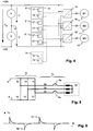
- Figure 5 shows a switch configuration to control the continuity of the device connections.
- At least one phase connection 2a, 2c is connected to the positive branch 3 and at least one further phase connection 2b to the negative branch 4.
- the continuity of the connections is determined using current measurements 8a, 8c, which are often already present in drive control.
- two phase connections 2a, 2c are connected to one branch and the remaining phase connection 2b to the other branch.
- the remaining phase connection is the one that does not have a current measurement (a redundant measurement is omitted for cost reasons). If one of the two measured currents is zero, the corresponding phase connection 2a or 2c is interrupted, if both are zero, the remaining phase connection 2b is interrupted.
- Figure 6 shows a profile of a differential voltage in the time domain during the operation of a converter 10.
- Each switchover of a phase connection 2 from one branch to the other leads to an abrupt and then decaying positive 61 or negative peak 62.
- the distance between successive peaks is a function of the modulation frequency of the converter, their height and decay time is a function of the capacities in lines 15 and drives 11.
- the tips overlap accordingly.
- a self-test of the insulation monitoring or the device 14 is carried out as follows. If it is known, for example in a test operating state, that no lines 15 are connected, there are no cable capacities and the peaks should be much smaller than if a line 15 is connected. A measure of the size of the peaks, ie a measure of a transient deviation of the function from a reference value, is thus formed. This is, for example, a characteristic variable such as an amplitude of the peak, an integral of absolute values, an RMS value, etc., in each case either filtered or unfiltered. If this measure exceeds a predetermined size in this test operating state, it is assumed that there is a fault in the insulation monitoring itself, in particular in the measurement value acquisition.
- Modulation frequencies are typically in the kHz range, for example around 6 to 8 kHz, stator frequencies in drives are typically between zero and 1000 Hz.
- bandpass filters preferably implemented in software, are used, the center frequency of which is equal to the respective stator frequency or modulation frequency .
- the modulation frequencies and / or stator frequencies are used for insulation monitoring 14 preferably transmitted by the converter controller (s) 9, for example via a fieldbus.
- these frequencies can be determined in one, several or all of the drives 11 by analyzing the intermediate circuit voltage (s) in the frequency range, for example by an FFT (Fast Fourier Transform), which determines signal components at different frequencies. This means that a signal component at a varying frequency can also be tracked in real time and its deviations from reference values can be determined.
- FFT Fast Fourier Transform
- the reference values S M1 , S M2 , E are also individually aligned to the drives 11, 11 ', 11 "used.
- the frequency components of a drive are determined based on theoretical specifications or preferably in a learning phase or” teach-in "phase One or more modulation frequencies and one or more output frequencies provided in operation are measured. A value higher by a predetermined factor is selected as the reference value.
- the amount of separate reference values gives the reference value envelope E.
- each drive can have its own reference value envelope E, but a common reference value envelope E can also be defined for simplification.
- the signal component at its current output frequency is calculated for each of the drives 11, 11 ', 11 "and compared with its reference value envelope E. If this is exceeded, an insulation fault is assumed. The same happens for the signal components at the modulation frequencies, whereby these are generally unchangeable, for example when f M1 the reference value S M1 is exceeded.
- two drives can, for example, temporarily have the same stator frequency, or work permanently with the same modulation frequency.
- the reference value can be the sum of the reference values for the two drives at this frequency
- the basic principle remains that the information about the converter states is taken into account when assessing the interference spectrum.
- the modulation frequencies is shown in the figure by way of example with the comparatively high reference value S M2 at f M2 , assuming two of the in Figure 7 represented three drives with the same modulation frequency f M2 work.
- FIG. 8 shows qualitatively a common frequency-voltage characteristic of a drive converter.
- Frequency and voltage typically relate to the frequency and voltage amplitude of the fundamental wave of the stator voltage.
- the signal component is preferably normalized or scaled with respect to the voltage amplitude (depending on the point of view), for example by dividing the signal component before or after filtering by the voltage amplitude.
- Mathematically essentially equivalent methods can be applied to the signal energy, or by raising reference values proportional to the voltage amplitude.
- Figure 9 shows a measuring arrangement for measuring intermediate circuit voltages: two measuring amplifiers 21, 21 'amplify the voltage at taps of voltage dividers R1 / R2 and R3 / R4 for detecting the upper and lower ones Partial tension.
- a microprocessor 22 which can be identical to the data processing unit 12 of the insulation monitoring device 14, determines the intermediate circuit voltage as the sum of the partial voltages for converter control, for example, and the differential voltage for insulation monitoring. Alternatively, the summation or difference formation can also be done using analog means.
- a fault impedance Zf is also shown, which illustrates that the symmetry of the voltages shifts in the event of an insulation fault.
- the insulation quality of the DC link itself can be determined from the differential voltage. Possible insulation faults in the drive 11 or in the line 15 are not visible in this state because the power semiconductors 1 are not conducting.
- the invention is explained on the basis of two-point inverters, but it can also be applied analogously to three-point inverters.
Landscapes
- Engineering & Computer Science (AREA)
- Power Engineering (AREA)
- Physics & Mathematics (AREA)
- General Physics & Mathematics (AREA)
- Inverter Devices (AREA)
- Testing Of Short-Circuits, Discontinuities, Leakage, Or Incorrect Line Connections (AREA)
Claims (17)
- Procédé de surveillance de l'isolation d'un système convertisseur statique dans une phase de test du système convertisseur statique lors de la mise en marche d'au moins un appareil électrique, le système convertisseur statique comprenant- un circuit intermédiaire de tension (7) pourvu d'au moins une branche positive (3) et une branche négative (4) ;- l'au moins un appareil électrique (11), lequel possède au moins deux bornes de phase (2) ; et- au moins un convertisseur statique (10) pourvu d'éléments de commutation (1) servant à la connexion électrique des bornes de phase (2) à la branche positive (3) ou à la branche négative (4) du circuit intermédiaire de tension (7) ;et le procédé comprenant les étapes suivantes :- dans une première configuration de test, mise en circuit d'un élément de commutation (1) ou mise en circuit simultanée de plusieurs éléments de commutation (1) en vue de connecter soit la branche positive (3), soit la branche négative (4) du convertisseur statique à une ou plusieurs bornes de phase (2),- mesure d'au moins l'une parmi- une tension de la branche positive (3) et- une tension de la branche négative (4) ;- détermination de valeurs de grandeurs caractéristiques ou d'une fonction d'au moins l'une de ces tensions mesurées ;- détermination de défauts d'isolation au niveau du circuit intermédiaire de tension (7) et/ou au niveau des bornes de phase (2) et/ou au niveau de l'appareil électrique (11) par comparaison de ces grandeurs caractéristiques avec des valeurs de référence correspondantes et, dans le cas où un écart par rapport aux valeurs de référence dépasse une mesure prédéfinie, supposition d'un défaut d'isolation ;- charge ou décharge du circuit intermédiaire à une tension de circuit intermédiaire réduite ;- application de courte durée de différentes tensions à au moins deux bornes de phase (2a, 2b, 2c) au moyen des éléments de commutation (1) du convertisseur statique ;- interprétation d'au moins un courant qui s'établit et/ou interprétation de la réaction d'une surveillance de court-circuit ; et- constatation, conformément à cette ou à ces interprétations, si au moins deux bornes de phase (2a, 2b, 2c) sont en court-circuit.
- Procédé selon la revendication 1, la fonction de l'au moins une tension mesurée étant une différence de tensions partielles ou le rapport entre une tension partielle et la tension totale du circuit intermédiaire (7) ou une tension partielle individuelle.
- Procédé selon la revendication 1 ou 2, l'étape de détermination de grandeurs caractéristiques comprenant cette fonction :- calcul d'une grandeur qui décrit le tracé dans le temps de la fonction.
- Procédé selon la revendication 3, la grandeur qui décrit le tracé dans le temps de la fonction étant- une constante de temps ; ou- une séquence de valeurs de la fonction ; ou- une période transitoire, ou- une intégrale de la fonction sur une durée prédéfinie ; ou- une valeur de la fonction à un instant prédéfini après la commutation du commutateur selon la configuration de test.
- Procédé selon la revendication 3 ou 4, comprenant l'étape supplémentaire :- calcul, à partir de la valeur de la grandeur qui décrit le tracé dans le temps de la fonction, d'une valeur correspondant à une amplitude d'un défaut de terre capacitif.
- Procédé selon l'une des revendications 1 à 5 ; comprenant l'étape supplémentaire servant à l'autotest de la surveillance de l'isolation :- dans une deuxième configuration de test, mise en circuit d'un élément de commutation (1) ou mise en circuit simultanée de plusieurs éléments de commutation (1) en vue de connecter à une ou plusieurs bornes de phase (2) la branche du convertisseur statique qui n'est pas connectée à l'une ou les plusieurs bornes de phase (2) dans la première configuration de test ; et- comparaison des fonctions de tensions partielles de la première et de la deuxième configuration de test et, dans le cas où les fonctions des deux configurations de test sont asymétriques l'une par rapport à l'autre, supposition de la présence d'un défaut dans les mesures des tensions de branche.
- Procédé selon la revendication 6, la comparaison des fonctions étant effectuée par- comparaison de grandeurs caractéristiques des fonctions des tensions partielles, notamment des différences entre la première et la deuxième configuration de test, et dans le cas où l'écart entre ces valeurs dépasse une mesure prédéfinie, supposition de la présence d'un défaut dans les mesures des tensions de branche.
- Procédé selon la revendication 7, la grandeur caractéristique des fonctions observées des tensions partielles étant une valeur absolue de la valeur finale fixe ou une valeur après une durée prédéfinie ou une intégrale de la fonction respective.
- Procédé selon l'une des revendications 1 à 8, comprenant l'étape supplémentaire servant à l'autotest de la surveillance de l'isolation dans un état de fonctionnement dans lequel le convertisseur statique (10) n'est pas relié à une ligne (15) :- supposition de la présence d'un défaut dans la surveillance de l'isolation dans le cas où les valeurs de la grandeur caractéristique de la fonction des tensions partielles dépassent une mesure prédéfinie.
- Procédé selon la revendication 9, la grandeur caractéristique étant une mesure d'un écart transitoire de la fonction par rapport à une valeur de référence et la fonction étant de préférence une tension différentielle.
- Procédé selon l'une des revendications 1 à 10, comprenant les étapes supplémentaires :- mise en circuit simultanée et de courte durée de plusieurs éléments de commutation (1) en vue de connecter au moins l'une des bornes de phase (2a, 2c) à la branche positive (3) et au moins l'une des autres bornes de phase (2b) à la branche négative (4) du convertisseur statique ;- mesure d'au moins un courant à travers l'une des bornes de phase (2) ainsi connectées pendant la mise en circuit ;- constatation si au moins une connexion des bornes de phase (2) avec l'appareil est interrompue en fonction de l'au moins une mesure du courant.
- Procédé selon la revendication 11, chacune des bornes de phase (2) étant connectée à la branche positive (3) ou à la branche négative (4) du convertisseur statique (10) et une interruption d'une connexion étant signalée lorsqu'au moins l'une des mesures du courant ne mesure aucun courant et, en option, la ou les connexions qui sont interrompues étant déterminées par comparaison des mesures du courant.
- Arrangement (14) de surveillance de l'isolation d'un système convertisseur statique lors de la mise en marche d'au moins un appareil électrique, le système convertisseur statique comprenant- un circuit intermédiaire de tension (7) pourvu d'au moins une branche positive (3) et une branche négative (4) ;- l'au moins un appareil électrique (11), lequel possède au moins deux bornes de phase (2) ; et- au moins un convertisseur statique (10) pourvu d'éléments de commutation (1) servant à la connexion électrique des bornes de phase (2) à la branche positive (3) ou à la branche négative (4) du circuit intermédiaire de tension (7) ;et l'arrangement (14) comprenant :- des moyens de commande destinés à déterminer un état de fonctionnement du convertisseur statique (10) par excitation des éléments de commutation (1) du convertisseur statique (10) ;- des moyens de mesure destinés à déterminer au moins l'une parmi- une tension de la branche positive (3) et- une tension de la branche négative (4) ;- une unité de traitement de données (12) destinée à déterminer des défauts d'isolation au niveau du circuit intermédiaire de tension (7) et/ou au niveau des bornes de phase (2) et/ou au niveau de l'appareil électrique (11) d'après les indications des tensions mesurées et de l'état de fonctionnement du convertisseur statique (10) ;- l'arrangement (14), outre les éléments de commutation (1) du convertisseur statique (10) qui sont de toute façon présents, ne possédant aucun moyen actif servant à l'injection de signaux de mesure en vue de la surveillance de l'isolation et/ou en vue de l'autotest de la surveillance de l'isolation ; et- l'arrangement (14) étant configuré pour mettre en œuvre le procédé selon l'une des revendications précédentes.
- Arrangement (14) selon la revendication 13, la mesure de la tension de circuit intermédiaire possédant deux dispositifs de mesure de tension partielle (5, 5') qui mesurent une première tension partielle entre la branche positive (3) et un point zéro (6) ou une deuxième tension partielle entre le point zéro (6) et la branche négative (4) ; et l'unité de traitement de données (12) étant configurée pour déterminer des défauts d'isolation à l'aide d'une fonction de l'une ou des deux tensions partielles, la fonction étant de préférence une différence des tensions partielles ou un rapport entre une tension partielle et la tension totale du circuit intermédiaire ou une tension partielle individuelle.
- Arrangement (14) selon l'une des revendications 13 ou 14, l'arrangement (14) faisant partie intégrante d'une commande de convertisseur statique (9).
- Arrangement (14) selon l'une des revendications 13 à 15, l'arrangement étant équipé d'un moyen de communication (13) en vue de la détermination de l'état de fonctionnement, lequel moyen de communication (13) est configuré pour communiquer des instructions de commutation à une commande de convertisseur statique (9) .
- Procédé de fabrication d'un appareil de surveillance (9 ; 14) destiné à la surveillance de l'isolation de systèmes convertisseurs statiques lors de la mise en marche d'au moins un appareil électrique, comprenant les étapes- fourniture d'une unité de traitement de données (12) et d'une unité de mémoire de l'appareil de surveillance (9 ; 14) ainsi que des entrées de mesure ou des moyens de communication servant à acquérir des valeurs mesurées et à les communiquer à l'unité de traitement de données (12) ; et- mémorisation d'un code de programme dans une unité de mémoire de l'appareil de surveillance (14) ;- le code de programme, lors de son exécution dans l'unité de traitement de données (12), provoquant la mise en œuvre du procédé selon l'une des revendications 1 à 12.
Applications Claiming Priority (1)
| Application Number | Priority Date | Filing Date | Title |
|---|---|---|---|
| CH16022006 | 2006-10-06 |
Publications (3)
| Publication Number | Publication Date |
|---|---|
| EP1909368A2 EP1909368A2 (fr) | 2008-04-09 |
| EP1909368A3 EP1909368A3 (fr) | 2016-08-24 |
| EP1909368B1 true EP1909368B1 (fr) | 2020-05-20 |
Family
ID=37560756
Family Applications (2)
| Application Number | Title | Priority Date | Filing Date |
|---|---|---|---|
| EP07405298.6A Ceased EP1909368B1 (fr) | 2006-10-06 | 2007-10-04 | Agencement de commutation et procédé de surveillance d'isolation pour des applications de convertisseur |
| EP07405299.4A Ceased EP1909369B1 (fr) | 2006-10-06 | 2007-10-04 | Agencement de commutation et procédé de surveillance d'isolation pour des applications de convertisseur en fonctionnement |
Family Applications After (1)
| Application Number | Title | Priority Date | Filing Date |
|---|---|---|---|
| EP07405299.4A Ceased EP1909369B1 (fr) | 2006-10-06 | 2007-10-04 | Agencement de commutation et procédé de surveillance d'isolation pour des applications de convertisseur en fonctionnement |
Country Status (2)
| Country | Link |
|---|---|
| US (1) | US8310242B2 (fr) |
| EP (2) | EP1909368B1 (fr) |
Cited By (1)
| Publication number | Priority date | Publication date | Assignee | Title |
|---|---|---|---|---|
| EP3014753B1 (fr) * | 2013-06-28 | 2023-02-22 | Schmidhauser AG | Convertisseur |
Families Citing this family (53)
| Publication number | Priority date | Publication date | Assignee | Title |
|---|---|---|---|---|
| US7759888B2 (en) * | 2005-04-15 | 2010-07-20 | Hitachi, Ltd. | AC motor controller |
| CN101981774B (zh) * | 2008-04-03 | 2014-06-25 | 西门子公司 | 用于产生故障信号的方法、装置和现场设备 |
| US8513951B2 (en) | 2008-07-30 | 2013-08-20 | Northrop Grumman Systems Corporation | Method and apparatus for fast fault detection |
| DE102009021238A1 (de) * | 2009-05-14 | 2010-11-18 | Siemens Aktiengesellschaft | Verfahren zur Identifizierung von Verschmutzung und /oder Betauung von Bauelementen eines Spannungszwischenkreis-Umrichters |
| US8310272B2 (en) * | 2009-07-29 | 2012-11-13 | GM Global Technology Operations LLC | Method and system for testing electric automotive drive systems |
| EP2482088B1 (fr) * | 2009-09-24 | 2018-11-07 | Nissan Motor Co., Ltd. | Appareil et procédé pour détecter des anomalies de circuit haute tension |
| DE102009049934B4 (de) * | 2009-10-19 | 2014-05-15 | Sew-Eurodrive Gmbh & Co Kg | Aus einem elektrischen Wechselstromnetz versorgbares Elektrogerät und Verfahren zur Fehlererkennung |
| DE102010030079A1 (de) * | 2010-06-15 | 2011-12-15 | Robert Bosch Gmbh | Verfahren und Vorrichtung zur Überwachung des Isolationswiderstandes in einem ungeerdeten elektrischen Netz |
| DE102010030083A1 (de) * | 2010-06-15 | 2011-12-15 | Robert Bosch Gmbh | Schaltungsanordnung zur Bestimmung einer Spannungsschwankung von Leiterpotentialen in einem ungeerdeten elektrischen Netz |
| DE102010030129A1 (de) * | 2010-06-15 | 2011-12-15 | Robert Bosch Gmbh | Schaltungsanordnung zur Bestimmung einer Spannungsschwankung von Leiterpotentialen in einem ungeerdeten elektrischen Netz |
| DE102010030133A1 (de) | 2010-06-15 | 2011-12-15 | Robert Bosch Gmbh | Schaltungsanordnung zur Bestimmung einer Spannungsschwankung von Leiterpotentialen in einem ungeerdeten elektrischen Netz |
| DE102010054413A1 (de) | 2010-12-14 | 2011-08-25 | Daimler AG, 70327 | Verfahren zum Lokalisieren eines Isolationsfehlers |
| EP2487496A1 (fr) * | 2011-02-11 | 2012-08-15 | Saab Automobile Ab | Procédé de mesures d'isolation utilisant un circuit pré-chargé et de décharge |
| AT511790A3 (de) | 2011-07-26 | 2020-06-15 | Eaton Gmbh | Verfahren zur adaption eines lichtbogensensors |
| EP2568557B1 (fr) * | 2011-09-07 | 2014-02-26 | Siemens Aktiengesellschaft | Procédé de fonctionnement d'un disjoncteur à courant de fuite et disjoncteur à courant de fuite pour un convertisseur de courant |
| DE102011089606A1 (de) * | 2011-12-22 | 2013-06-27 | Ge Energy Power Conversion Gmbh | Verfahren zum Betreiben einer elektrischen Schaltung |
| FR2989235B1 (fr) * | 2012-04-06 | 2014-03-14 | Schneider Electric Ind Sas | Systeme de controle d'isolement pour reseau electrique securise |
| DE102012209586A1 (de) * | 2012-06-06 | 2013-12-12 | Bender Gmbh & Co. Kg | Isolationsfehlerüberwachung mit Signalqualitätsanzeige |
| US8970148B2 (en) * | 2012-07-31 | 2015-03-03 | Rockwell Automation Technologies, Inc. | Method and apparatus for reducing radiated emissions in switching power converters |
| EP2706365B1 (fr) * | 2012-09-06 | 2015-03-11 | Vetco Gray Controls Limited | Test d'un fusible |
| DE102013002018B4 (de) | 2013-02-06 | 2022-06-09 | Sew-Eurodrive Gmbh & Co Kg | Verfahren zur Isolationsüberwachung einer Schaltungsanordnung |
| US20140333286A1 (en) * | 2013-05-07 | 2014-11-13 | Eaton Corporation | Load panel branch circuit monitor employing an intelligent current sensor module |
| KR101452636B1 (ko) * | 2013-06-03 | 2014-10-22 | 엘에스산전 주식회사 | 인버터 시스템 및 이의 전력 케이블 상태 검출 방법 |
| CN104802655B (zh) * | 2014-01-24 | 2017-03-29 | 联合汽车电子有限公司 | 电动汽车电驱动系统高压直流端开路诊断系统 |
| FR3018609B1 (fr) * | 2014-03-14 | 2016-03-25 | Renault Sas | Procede et systeme de commande d'une machine electrique avec diagnostic de l'onduleur d'alimentation. |
| DE102014204870A1 (de) * | 2014-03-17 | 2015-09-17 | Continental Automotive Gmbh | Vorrichtung und Verfahren zur Überwachung einer elektrischen Isolation bei einem Bordnetz eines Fahrzeugs |
| WO2016098481A1 (fr) * | 2014-12-15 | 2016-06-23 | 日立オートモティブシステムズ株式会社 | Dispositif de conversion de puissance électrique |
| EP3073635B8 (fr) * | 2015-03-25 | 2018-11-21 | GE Renewable Technologies Wind B.V. | Protection d'un générateur à aimant permanent |
| CN106154076B (zh) * | 2015-04-17 | 2019-05-03 | 湖南南车时代电动汽车股份有限公司 | 用于检测逆变器故障的方法及装置 |
| DE102015207456B3 (de) * | 2015-04-23 | 2016-09-22 | Bender Gmbh & Co. Kg | Isolationsüberwachungsgerät mit Spannungsüberwachung und zugrunde liegendes Verfahren |
| CN105093132B (zh) * | 2015-06-30 | 2018-05-22 | 许昌许继软件技术有限公司 | 一种大功率整流器开路故障快速在线诊断方法 |
| DE102016200309B3 (de) | 2016-01-13 | 2017-03-09 | Bender Gmbh & Co. Kg | Verfahren zum Erkennen einer Unterbrechung eines aktiven Leiters in einem ungeerdeten Gleichspannungs-Stromversorgungssystem |
| DE102016208322B4 (de) * | 2016-05-13 | 2020-11-26 | Bender Gmbh & Co. Kg | Verfahren und Vorrichtung zur Fehlerlichtbogen-Erkennung in einem ungeerdeten Stromversorgungssystem |
| JP6714448B2 (ja) * | 2016-06-23 | 2020-06-24 | 株式会社日立産機システム | 電力変換装置および地絡箇所判定方法 |
| DE102016214063A1 (de) * | 2016-07-29 | 2018-02-01 | Schmidhauser Ag | Schaltung zum Vorladen eines Zwischenkreises und elektrisches System |
| DE102017001849A1 (de) | 2017-02-25 | 2018-08-30 | Man Truck & Bus Ag | Technik zur Isolationsüberwachung in Fahrzeugen |
| DE102017002483A1 (de) | 2017-03-15 | 2018-09-20 | Man Truck & Bus Ag | Technik zur Isolationsüberwachung in Fahrzeugen |
| EP3435503A1 (fr) * | 2017-07-27 | 2019-01-30 | Siemens Aktiengesellschaft | Localisation d'un défaut de terre dans un réseau it |
| WO2019146114A1 (fr) * | 2018-01-29 | 2019-08-01 | 東芝三菱電機産業システム株式会社 | Dispositif et procédé de surveillance de dégradation d'isolation |
| US10848053B2 (en) | 2018-07-13 | 2020-11-24 | Kohler Co. | Robust inverter topology |
| US10756532B2 (en) | 2018-07-13 | 2020-08-25 | Kohler Co. | Ground fault minimization |
| DE102018126235B4 (de) * | 2018-10-22 | 2020-06-04 | Sma Solar Technology Ag | Verfahren zur Isolationswiderstandsmessung in Wechselrichtern mit Mehrpunkttopologie und Wechselrichter mit Mehrpunkttopologie |
| US11604217B2 (en) * | 2018-11-13 | 2023-03-14 | Shenzhen Vmax New Energy Co., Ltd. | Insulation detection circuit and detection method thereof for two-way on-board charger |
| DE102018221479A1 (de) * | 2018-12-12 | 2020-06-18 | Robert Bosch Gmbh | Schaltungsanordnung zur Fehlererkennung in einem ungeerdeten Hochvoltsystem |
| DE102019217747A1 (de) * | 2019-11-18 | 2021-05-20 | Rolls-Royce Deutschland Ltd & Co Kg | Ermitteln eines Inverterkurzschlusses zwischen zwei Phasen |
| DE102020111901B3 (de) * | 2020-05-03 | 2021-04-22 | Iav Gmbh Ingenieurgesellschaft Auto Und Verkehr | Verfahren und Vorrichtung zur Bestimmung des Zwischenkreisstromes eines Stromrichters |
| CN112557754B (zh) * | 2020-11-20 | 2021-11-16 | 珠海格力电器股份有限公司 | 光伏逆变器的绝缘阻抗检测方法及装置 |
| DE102021204209B4 (de) | 2021-04-28 | 2025-06-05 | Bucher Hydraulics Ag | Frequenzumrichter |
| DE102021127848A1 (de) * | 2021-10-26 | 2023-04-27 | Bender Gmbh & Co. Kg | Verfahren und Vorrichtung zur Erkennung und Lokalisierung von zyklischen Kurzzeit-Isolationsfehlern in einem ungeerdeten Stromversorgungssystem |
| EP4209790B1 (fr) | 2022-01-05 | 2024-10-09 | Hamilton Sundstrand Corporation | Procédé et système de surveillance d'isolation dans les districts de puissance d'aéronef et leurs charges |
| DE102022124416A1 (de) | 2022-09-22 | 2024-03-28 | Bayerische Motoren Werke Aktiengesellschaft | Verfahren zum Laden eines Zwischenkreiskondensators eines Zwischenkreises einer elektrischen Antriebseinrichtung für ein Kraftfahrzeug |
| CN118534188B (zh) * | 2024-07-24 | 2024-10-01 | 国网陕西省电力有限公司电力科学研究院 | Gis隔离开关驱动电机功率采样方法、装置及故障诊断方法 |
| WO2026063914A1 (fr) * | 2024-09-17 | 2026-03-26 | General Electric Renovables Espana S.L. | Système et procédé de détection de dégradation de câbles d'une machine électrique polyphasée |
Family Cites Families (18)
| Publication number | Priority date | Publication date | Assignee | Title |
|---|---|---|---|---|
| DE3135239A1 (de) | 1981-09-05 | 1983-03-17 | Basf Ag, 6700 Ludwigshafen | N-substituierte brenztraubensaeureamide, verfahren zu ihrer herstellung und diese enthaltende fungizide |
| JPH04210779A (ja) | 1990-12-14 | 1992-07-31 | Mitsubishi Electric Corp | インバータ装置の地絡検出器及び地絡検出方法 |
| DE4203299A1 (de) | 1992-01-31 | 1993-08-05 | Siemens Ag | Schaltungsanordnung zur isolationsueberwachung von spannungszwischenkreisen |
| DE4339946A1 (de) | 1993-11-24 | 1995-06-01 | Walther Bender Gmbh & Co Kg Di | Verfahren und Einrichtung zur Isolationsüberwachung vom ungeerdeten Gleich- und Wechselstromnetzen |
| JPH07241002A (ja) * | 1994-02-24 | 1995-09-12 | Toyota Motor Corp | 電気自動車の漏電検出装置 |
| JP3224977B2 (ja) * | 1994-12-12 | 2001-11-05 | 本田技研工業株式会社 | 非接地電源の絶縁検出方法及び装置 |
| DE19503749C1 (de) | 1995-02-04 | 1996-04-18 | Daimler Benz Ag | Fahrzeug mit einem brennstoffzellen- oder batteriegespeisten Energieversorgungsnetz |
| IT1276445B1 (it) | 1995-06-27 | 1997-10-31 | Fiat Auto Spa | Metodo e dispositivo di monitoraggio e segnalazione della assenza di isolamento elettrico tra impianto di trazione e carrozzeria in veicoli |
| US5818192A (en) * | 1995-08-04 | 1998-10-06 | The Boeing Company | Starting of synchronous machine without rotor position of speed measurement |
| JP2000116144A (ja) * | 1998-09-30 | 2000-04-21 | Yaskawa Electric Corp | インバータ装置 |
| US6291987B1 (en) * | 1999-10-28 | 2001-09-18 | General Electric Company | Method and system for detecting incipient failures in a power inverter |
| DE10106200C1 (de) | 2001-02-10 | 2002-09-05 | Ean Elektroschaltanlagen Gmbh | Verfahren und Einrichtung zur Isolationsüberwachung ungeerdeter elektrischer Netze |
| DE10126168A1 (de) * | 2001-05-30 | 2002-12-05 | Kostal Leopold Gmbh & Co Kg | Verfahren zum Bestimmen der Frequenz der im Ankerstromsignal eines kommutierten Gleichstrommotors enthaltenen Stromrippel |
| US6856137B2 (en) * | 2002-02-19 | 2005-02-15 | Bae Systems Controls Inc. | Ground fault detection system and method |
| US6900643B2 (en) * | 2003-08-06 | 2005-05-31 | Ballard Power Systems Corporation | Ride through in electronic power converters |
| DE112004003035B4 (de) * | 2004-12-27 | 2018-02-08 | Danfoss Drives A/S | Verfahren zur Feststellung von Zuständen mit Erdschluss bei einer Motorsteuerung |
| JP4554501B2 (ja) * | 2005-01-18 | 2010-09-29 | ファナック株式会社 | モータの絶縁抵抗劣化検出方法、絶縁抵抗劣化検出装置およびモータ駆動装置 |
| JP4254738B2 (ja) * | 2005-03-31 | 2009-04-15 | 株式会社デンソー | 車両用発電機の発電制御装置 |
-
2007
- 2007-10-04 EP EP07405298.6A patent/EP1909368B1/fr not_active Ceased
- 2007-10-04 EP EP07405299.4A patent/EP1909369B1/fr not_active Ceased
- 2007-10-05 US US11/867,687 patent/US8310242B2/en active Active
Non-Patent Citations (1)
| Title |
|---|
| None * |
Cited By (1)
| Publication number | Priority date | Publication date | Assignee | Title |
|---|---|---|---|---|
| EP3014753B1 (fr) * | 2013-06-28 | 2023-02-22 | Schmidhauser AG | Convertisseur |
Also Published As
| Publication number | Publication date |
|---|---|
| EP1909369B1 (fr) | 2020-05-20 |
| EP1909368A2 (fr) | 2008-04-09 |
| EP1909368A3 (fr) | 2016-08-24 |
| US8310242B2 (en) | 2012-11-13 |
| EP1909369A3 (fr) | 2016-08-24 |
| EP1909369A2 (fr) | 2008-04-09 |
| US20080084215A1 (en) | 2008-04-10 |
Similar Documents
| Publication | Publication Date | Title |
|---|---|---|
| EP1909368B1 (fr) | Agencement de commutation et procédé de surveillance d'isolation pour des applications de convertisseur | |
| DE112014002853B4 (de) | Isolationsdetektor und elektrische Vorrichtung | |
| EP3637114B1 (fr) | Système de haut voltage et procédé de surveillance des erreurs d'isolation dans un système de haut voltage | |
| EP3625863B1 (fr) | Localisation d'un défaut de terre dans un réseau it | |
| DE102010010042B4 (de) | System und Verfahren zum Detektieren eines Isolationsverlusts in einem Motorsystem mit einem Wechselrichter | |
| DE102011014561B4 (de) | Verfahren und Vorrichtung zum Überwachen einer Elektromotor-Steuerschaltung | |
| EP2205984B1 (fr) | Montage destiné à surveiller une isolation électrique | |
| EP2851692B1 (fr) | Système de recherche de défaut d'isolation doté d'une alimentation à sélection de branchement et système de surveillance d'isolation sélectif ainsi que procédé de détermination d'une impédance de ligne inter-automatique entre deux sous-systèmes | |
| DE102019103757B3 (de) | Verfahren, Isolationswächter und System zur Isolationsüberwachung einer dynamisch umkonfigurierbaren modularen Wechselstrombatterie | |
| DE102011076320B4 (de) | Erdungsüberwachungs-Vorrichtung und Ladesystem | |
| EP3126181B1 (fr) | Procédé de contrôle d'une connexion entre un réseau basse tension et une batterie, et véhicule automobile | |
| EP2887081B1 (fr) | Dispositif destiné à la surveillance d'isolation | |
| DE102011050590A1 (de) | Isolationsüberwachung mit einem Prüfsignal variabler Frequenz | |
| EP0642027A1 (fr) | Procédé et dispositif pour détecter des défaults à la terre des fils conducteurs dans une machine électrique | |
| EP3631976B1 (fr) | Procédé servant à identifier un contact défectueux dans une installation photovoltaïque | |
| EP3069359B1 (fr) | Procédé et dispositif de surveillance de condensateurs de traversée pour réseau de courant alternatif triphasé | |
| WO2018007106A1 (fr) | Procédé permettant de détecter une panne dans un réseau de bord | |
| EP3451477A1 (fr) | Détection d'une erreur dans un système de transmission de courant continu | |
| DE112019000888T5 (de) | System zur Erdung und Diagnose | |
| EP3433625B1 (fr) | Procédé de détection d'une défaillance, dispositif de commande, capteur batterie et réseau de bord | |
| EP3824524B1 (fr) | Procédé de vérification d'un point de séparation d'un onduleur photovoltaïque et un tel onduleur photovoltaïque | |
| WO2015144390A1 (fr) | Procédé de détection et de signalement d'un défaut de contact à l'intérieur d'un module photovoltaïque | |
| EP1340988B1 (fr) | Méthode et appareil pour mesurer l'impedance dans un réseau d'alimentation électrique | |
| EP3532857B1 (fr) | Dispositif et procédé pour le diagnostic de la détection d'un courant électrique polyphasé | |
| DE102013013950A1 (de) | Verfahren, Messanordnung und Messgerät zur Bestimmung von lsolationswiderständen von Einzelzellen einer Hochvoltbatterie |
Legal Events
| Date | Code | Title | Description |
|---|---|---|---|
| PUAI | Public reference made under article 153(3) epc to a published international application that has entered the european phase |
Free format text: ORIGINAL CODE: 0009012 |
|
| AK | Designated contracting states |
Kind code of ref document: A2 Designated state(s): AT BE BG CH CY CZ DE DK EE ES FI FR GB GR HU IE IS IT LI LT LU LV MC MT NL PL PT RO SE SI SK TR |
|
| AX | Request for extension of the european patent |
Extension state: AL BA HR MK RS |
|
| PUAL | Search report despatched |
Free format text: ORIGINAL CODE: 0009013 |
|
| AK | Designated contracting states |
Kind code of ref document: A3 Designated state(s): AT BE BG CH CY CZ DE DK EE ES FI FR GB GR HU IE IS IT LI LT LU LV MC MT NL PL PT RO SE SI SK TR |
|
| AX | Request for extension of the european patent |
Extension state: AL BA HR MK RS |
|
| RIC1 | Information provided on ipc code assigned before grant |
Ipc: H02H 7/122 20060101AFI20160719BHEP Ipc: G01R 31/02 20060101ALI20160719BHEP Ipc: G01R 27/18 20060101ALI20160719BHEP |
|
| STAA | Information on the status of an ep patent application or granted ep patent |
Free format text: STATUS: REQUEST FOR EXAMINATION WAS MADE |
|
| 17P | Request for examination filed |
Effective date: 20170221 |
|
| RBV | Designated contracting states (corrected) |
Designated state(s): AT BE BG CH CY CZ DE DK EE ES FI FR GB GR HU IE IS IT LI LT LU LV MC MT NL PL PT RO SE SI SK TR |
|
| AKX | Designation fees paid |
Designated state(s): DE |
|
| AXX | Extension fees paid |
Extension state: MK Extension state: RS Extension state: BA Extension state: AL Extension state: HR |
|
| STAA | Information on the status of an ep patent application or granted ep patent |
Free format text: STATUS: EXAMINATION IS IN PROGRESS |
|
| 17Q | First examination report despatched |
Effective date: 20190213 |
|
| GRAP | Despatch of communication of intention to grant a patent |
Free format text: ORIGINAL CODE: EPIDOSNIGR1 |
|
| STAA | Information on the status of an ep patent application or granted ep patent |
Free format text: STATUS: GRANT OF PATENT IS INTENDED |
|
| INTG | Intention to grant announced |
Effective date: 20190912 |
|
| GRAJ | Information related to disapproval of communication of intention to grant by the applicant or resumption of examination proceedings by the epo deleted |
Free format text: ORIGINAL CODE: EPIDOSDIGR1 |
|
| STAA | Information on the status of an ep patent application or granted ep patent |
Free format text: STATUS: EXAMINATION IS IN PROGRESS |
|
| GRAP | Despatch of communication of intention to grant a patent |
Free format text: ORIGINAL CODE: EPIDOSNIGR1 |
|
| STAA | Information on the status of an ep patent application or granted ep patent |
Free format text: STATUS: GRANT OF PATENT IS INTENDED |
|
| INTG | Intention to grant announced |
Effective date: 20200212 |
|
| RIC1 | Information provided on ipc code assigned before grant |
Ipc: H02H 7/122 20060101AFI20200204BHEP Ipc: G01R 27/18 20060101ALI20200204BHEP |
|
| GRAS | Grant fee paid |
Free format text: ORIGINAL CODE: EPIDOSNIGR3 |
|
| GRAA | (expected) grant |
Free format text: ORIGINAL CODE: 0009210 |
|
| STAA | Information on the status of an ep patent application or granted ep patent |
Free format text: STATUS: THE PATENT HAS BEEN GRANTED |
|
| AK | Designated contracting states |
Kind code of ref document: B1 Designated state(s): DE |
|
| REG | Reference to a national code |
Ref country code: DE Ref legal event code: R096 Ref document number: 502007016881 Country of ref document: DE |
|
| REG | Reference to a national code |
Ref country code: DE Ref legal event code: R097 Ref document number: 502007016881 Country of ref document: DE |
|
| PLBE | No opposition filed within time limit |
Free format text: ORIGINAL CODE: 0009261 |
|
| STAA | Information on the status of an ep patent application or granted ep patent |
Free format text: STATUS: NO OPPOSITION FILED WITHIN TIME LIMIT |
|
| 26N | No opposition filed |
Effective date: 20210223 |
|
| REG | Reference to a national code |
Ref country code: DE Ref legal event code: R081 Ref document number: 502007016881 Country of ref document: DE Owner name: LENZE SWISS AG, CH Free format text: FORMER OWNER: SCHMIDHAUSER AG, ROMANSHORN, CH |
|
| PGFP | Annual fee paid to national office [announced via postgrant information from national office to epo] |
Ref country code: DE Payment date: 20231018 Year of fee payment: 17 |
|
| REG | Reference to a national code |
Ref country code: DE Ref legal event code: R119 Ref document number: 502007016881 Country of ref document: DE |
|
| PG25 | Lapsed in a contracting state [announced via postgrant information from national office to epo] |
Ref country code: DE Free format text: LAPSE BECAUSE OF NON-PAYMENT OF DUE FEES Effective date: 20250501 |