EP1909532A1 - Système audio de conférence - Google Patents
Système audio de conférence Download PDFInfo
- Publication number
- EP1909532A1 EP1909532A1 EP05768404A EP05768404A EP1909532A1 EP 1909532 A1 EP1909532 A1 EP 1909532A1 EP 05768404 A EP05768404 A EP 05768404A EP 05768404 A EP05768404 A EP 05768404A EP 1909532 A1 EP1909532 A1 EP 1909532A1
- Authority
- EP
- European Patent Office
- Prior art keywords
- audio
- audio data
- microphone
- level detector
- analog
- Prior art date
- Legal status (The legal status is an assumption and is not a legal conclusion. Google has not performed a legal analysis and makes no representation as to the accuracy of the status listed.)
- Granted
Links
Images


Classifications
-
- H—ELECTRICITY
- H04—ELECTRIC COMMUNICATION TECHNIQUE
- H04R—LOUDSPEAKERS, MICROPHONES, GRAMOPHONE PICK-UPS OR LIKE ACOUSTIC ELECTROMECHANICAL TRANSDUCERS; ELECTRIC HEARING AIDS; PUBLIC ADDRESS SYSTEMS
- H04R3/00—Circuits for transducers
-
- H—ELECTRICITY
- H04—ELECTRIC COMMUNICATION TECHNIQUE
- H04R—LOUDSPEAKERS, MICROPHONES, GRAMOPHONE PICK-UPS OR LIKE ACOUSTIC ELECTROMECHANICAL TRANSDUCERS; ELECTRIC HEARING AIDS; PUBLIC ADDRESS SYSTEMS
- H04R3/00—Circuits for transducers
- H04R3/005—Circuits for transducers for combining the signals of two or more microphones
-
- H—ELECTRICITY
- H04—ELECTRIC COMMUNICATION TECHNIQUE
- H04R—LOUDSPEAKERS, MICROPHONES, GRAMOPHONE PICK-UPS OR LIKE ACOUSTIC ELECTROMECHANICAL TRANSDUCERS; ELECTRIC HEARING AIDS; PUBLIC ADDRESS SYSTEMS
- H04R27/00—Public address systems
-
- H—ELECTRICITY
- H04—ELECTRIC COMMUNICATION TECHNIQUE
- H04R—LOUDSPEAKERS, MICROPHONES, GRAMOPHONE PICK-UPS OR LIKE ACOUSTIC ELECTROMECHANICAL TRANSDUCERS; ELECTRIC HEARING AIDS; PUBLIC ADDRESS SYSTEMS
- H04R2201/00—Details of transducers, loudspeakers or microphones covered by H04R1/00 but not provided for in any of its subgroups
- H04R2201/40—Details of arrangements for obtaining desired directional characteristic by combining a number of identical transducers covered by H04R1/40 but not provided for in any of its subgroups
- H04R2201/403—Linear arrays of transducers
-
- H—ELECTRICITY
- H04—ELECTRIC COMMUNICATION TECHNIQUE
- H04R—LOUDSPEAKERS, MICROPHONES, GRAMOPHONE PICK-UPS OR LIKE ACOUSTIC ELECTROMECHANICAL TRANSDUCERS; ELECTRIC HEARING AIDS; PUBLIC ADDRESS SYSTEMS
- H04R2420/00—Details of connection covered by H04R, not provided for in its groups
- H04R2420/07—Applications of wireless loudspeakers or wireless microphones
Definitions
- the present invention relates to a conference audio system and, more particularly, to a conference audio system capable of avoiding front-end-clipping of delayed speech in a cordless audio conferencing system using infrared light.
- a conference audio system When a conference attended by many persons is held, a conference audio system is used, in which speaker's utterance is picked up by a microphone, amplified by an amplifier, and output from a speaker in a conference hall so that the speaker's utterance can be heard by all attendees.
- many microphones are used. If many microphones are being turned on at the same time, that is, in an active state, audios picked up by these microphones are amplified and output from the speaker, and therefore, audios other than those of the speaker are heard as noises and the audio of the speaker cannot be heard clearly. In addition, a howl becomes more likely to occur. Because of this, a system has been widely used, in which an attendee turns on a microphone switch at hand when making a statement and turns off the switch after completing the statement.
- Fig. 6 shows a concept of the system.
- Fig. 6 on a table 1 in a conference hall, many microphones 11, 12, ⁇ , and In are arranged erectly on microphone stands 21, 22, ⁇ , and 2n. There are cases where each person uses each microphone and where two or more persons share one microphone.
- the microphone stands 21, 22, ⁇ , and 2n are each provided with a switch with which each microphone is turned on or off by the operation of an attendee. Audio signals from a microphone that has been turned on by the switch operation are input to a mixer 2 and the audio signals mixed in the mixer 2 are amplified by an amplifier 3 and the audios are output toward the attendees from a speaker 4 installed in the conference hall.
- Fig. 7 shows the time delay.
- a waveform a represented by the solid line shows an attendee's utterance signal and a waveform b represented by the dotted line shows an audio signal from the speaker 4.
- a time delay ⁇ t between the waveform a and the waveform b.
- the time delay ⁇ t is about 10 ms and there will arise no auditory problem because there is no auditorily uncomfortable feeling.
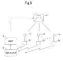
- a conference audio system of cordless type as shown in Fig. 8 is proposed.
- the microphones 11, 12, ⁇ , and 1n stand respectively on microphone stands 31, 32, ⁇ , and 3n placed on the table.
- Each of the microphone stands 31, 32, ⁇ , and 3n incorporates a transmitter and transmits an audio signal converted in the microphone to a receiver 5.
- This transmission/reception system may be an optical communication system that uses infrared light etc., or a communication system that uses radio waves.
- the receiver 5 demodulates the received signal into an audio signal and the amplifier 3 amplifies the demodulated signal, and thus the audio is output from the speaker 4 installed in the conference hall toward the attendees.
- a conference audio system equipped with an automatic mute release device is proposed.
- an audio level detector is provided, which detects utterance or silence depending on whether or not the output level of each microphone exceeds a predetermined level, and normally, the microphone is put in an off state, that is, in a state of mute, and the audio level detector, when detecting utterance, turns on the microphone, that is, the mute is released.
- the automatic mute release device can also be applied to a wired system shown in Fig 6 and a cordless system shown in Fig. 8 .
- an audio level picked up by a microphone is detected and when the audio level becomes equal to or exceeds a predetermined threshold level (hereinafter, referred to as a "threshold"), the audio signal converted in the microphone is turned on.
- a predetermined threshold level hereinafter, referred to as a "threshold”
- the audio signal converted in the microphone is turned on.
- a method of automatically detecting beginning of speech in which when an analog audio signal level from a microphone is equal to or greater than a threshold, a voice switch is turned on and while the voice switch is on, a digital recording circuit is activated and at the same time, the analog audio signal is input to a digital recording circuit for digital recording with a delay by a delay circuit corresponding to the maximum operation delay time when the voice switch is switched from the off-state to on-state (for example, refer to Patent document 1).
- the application of the technique described in Patent document 1 to a conference audio system will result in always causing a fixed time delay between when voice utterance is picked up by a microphone and when the audio is output from a speaker.
- a recording device based on the same concept as that of the invention described in Patent document 1 is also known, which uses a tape recorder by an endless tape in place of a digital recording circuit (for example, refer to Patent document 2).
- the application of the invention described in Patent document 2 to a conference audio system will also result in the same problem as that encountered when the invention described in Patent document 1 is applied to a conference audio system.
- an audio communication recording device in which an audio signal input from a microphone is converted into a digital signal and when the quantity of data stored in an FIFO buffer reaches a predetermined quantity, if there is no audio signal, the data is discarded and if there is an audio signal, the data is stored in the buffer or transmitted (refer to Patent document 3).
- the invention described in Patent document 3 states that it is possible to realize a natural conversation because a delay time between when the audio signal is received and when the audio is heard is short.
- Patent document 1 Japanese Unexamined Patent Application Publication No. 60-163250
- Patent document 2 Japanese Unexamined Utility Model Application Publication No. 60-142805
- Patent document 3 Japanese Unexamined Patent Application Publication No. 8-265337
- the present invention has been achieved in order to eliminate the problems of the prior art as described above, and an object thereof is to provide a conference audio system capable of eliminating an uncomfortable feeling by reducing the delay time between the utterance toward a microphone and the output of the audio from a speaker even in a system including an automatic mute release device that automatically turns on only the microphone that has picked up the audio when the audio is uttered.
- the present invention includes a plurality of microphones, an analog/digital converter that converts an audio signal from each microphone into a digital signal, an audio level detector that detects utterance or silence depending on whether or not the level of the converted digital signal exceeds a predetermined level, an audio data storage unit that temporarily stores the digital signal detected its utterance by the audio level detector and converted by the analog/digital converter, a controller that controls the storage of audio data to the audio data storage unit and the reading of the stored audio data, and a digital/analog converter that converts the read audio data into an analog audio signal, and the reading controller hastens a read timing of the audio data in accordance with a time period of silent portion when the audio level detector detects silence in a series of the audio data.
- the audio level detector detects the utterance and the audio data storage unit stores audio data picked up by the microphone and converted digitally.
- the stored audio data is read under the control of the controller and converted into an analog signal. If the utterance toward the microphone is interrupted temporarily due to breathing etc. , the audio level detector determines the state as silence and hastens the read timing of the audio data by the time period corresponding to the silent time.
- the audio is converted into an analog signal with a delay from the time point of utterance, however, when the utterance is interrupted temporarily, the audio is converted into an analog signal with a delay time reduced by the time period of interrupt, and then, the audio is converted into an analog signal substantially in synchronization with the utterance. If, for example, the speaker is driven by the analog signal, although there occurs a time delay only at the beginning of the utterance, soon the audio is output from the speaker without time delay, and it is possible to obtain a conference audio system without an uncomfortable feeling.
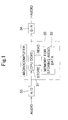
- Fig. 1 shows essential parts in the embodiment of the conference audio system according to the present invention, however, a microphone which is an entrance of an audio signal, a speaker which is an outlet of an audio, an amplifier provided before the speaker, etc. , are not shown schematically.
- the constitutional parts shown in Fig. 1 are arranged in accordance with each microphone.
- an analog/digital converter 33 which converts an audio signal, which is an analog signal converted by each microphone, into a digital signal.
- the digital audio signal converted by the analog/digital converter 33 is input to a central processing unit (hereinafter, referred to as "CPU") 31 in a microcomputer 30.
- the microcomputer includes a read-only-memory (ROM), a random-access-memory (RAM), etc. , with the CPU 31 as a controller as the central component.
- the RAM is used as an audio data storage unit 32.
- the CPU 31 as a controller carries out the control to store the audio data in the audio data storage unit 32 and the control to read the audio data from the audio data storage unit 32.
- the digital audio data read from the audio data storage unit 32 is converted into an analog audio signal by a digital/analog converter 34 and a speaker is driven by the analog audio signal via an amplifier not shown schematically and the audio is output from the speaker.
- the analog signal converted by the digital/analog converter 34 in each microphone is input to the mixer as described with reference to Fig. 6 via, for example, a cable, or the analog signal is transmitted from the cordless signal transmitter as described with reference to Fig. 8 and received by the receiver to drive the speaker via the amplifier.
- audio signals from a number of microphones, or light signals or radio waves modulated by the audio signal are sent.
- the automatic mute is released by an automatic mute release device and the audio signal, light signal, or radio wave is sent to the mixer or receiver, and the audio signal or demodulated audio signal is output from the speaker.
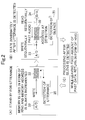
- Fig. 2(A) shows an image of a standby state for utterance by the audio level detector.
- the audio level detector detects utterance or silence depending on whether or not the level of the digital audio signal picked up by the microphone and converted by the analog/digital converter 33 exceeds a predetermined level, that is, a threshold, and the detector itself is a well-known technique.
- the block denoted by "detection of utterance” corresponds to an audio level detector 35.
- the audio level detector 35 detects the level of the digital audio signal and stores the digital audio signal in the audio data storage unit 32 when the level exceeds the threshold.
- the audio data storage unit 32 uses a memory with a fixed amount of capacity in the form of a ring and always increments the memory address regardless of the detection by the audio data storage unit. In other words, the digital audio data is stored sequentially in each address and rewritten.
- the control of the memory is carried out by the controller 31.
- Fig. 2(B) shows an image of a state immediately after the audio level detector 35 detects utterance.
- the controller 31 sequentially writes the digital audio data in the audio data storage unit 32. Further, the controller 31 causes the digital audio data to be read sequentially from the audio data storage unit 32 with a predetermined time delayed from the point of time of the detection of utterance, for example, of about 100 to 200 ms, which will occur inevitably. As a result, the writing to the audio data storage unit 32 and the reading from the audio data storage unit 32 are carried out at the same time.
- Fig. 2(B) shows an image of a state immediately after the audio level detector 35 detects utterance.
- the audio data stored in the audio data storage unit 32 is represented by "past audio", however, the wording "past” used here means “immediately before” and therefore the “past audio” means the audio immediately before the data is read. In this manner, immediately after the audio level detector 35 detects the utterance, the audio is output from the speaker with a fixed time delay. In this operation mode, the audio level detector 35 is ready to detect silence.
- the controller 31 stops the writing to the audio data storage unit 32 at that point of time, however, causes the reading from the audio data storage unit 32 to continue.
- Fig. 2(C) shows this operation.
- the controller 31 causes the reading to continue.
- the time delay of the audio output from the speaker is shortened by the time period corresponding to the above silent time.
- the controller 31 stops the writing to the audio data storage unit 32, however, causes the reading from the audio data storage unit 32 to continue. Then, at the point of time when the audio level detector 35 detects utterance again, the time delay is further shortened by the time period corresponding to the above silent time and then the audio is output from the speaker.
- the maximum value of the time delay to be shortened is the predetermined time of about 100 to 200 ms as described above, however, when the total of the time delays to be shortened several times reaches the above predetermined time, there is no time delay afterward and therefore the audio is output from the speaker in real time.
- the first silent time is the same as the predetermined time or longer than that, the audio is output from the speaker in real time immediately after that.
- Fig. 3(a) to Fig. 5 show images of the operation in the embodiment.
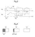
- Figs. 3 (a) and 3 (b) show the operation with an example of an audio signal waveform:
- Fig. 3 (a) shows an analog audio signal converted by a microphone;
- Fig. 3 (b) shows an audio signal that is read from the audio data storage unit, converted into an analog signal, and output from a speaker.
- the utterance or silence of the analog audio signal converted in the microphone is detected by the audio level detector depending on whether or not the predetermined threshold SL is exceeded.
- the audio is output from the speaker with a delay of ⁇ t from the analog audio signal converted in the microphone.
- Fig. 4 (a) shows an image of the audio data storage unit at this time, showing that the reading is carried out with a delay corresponding to the capacity of memory corresponding to ⁇ t1 of the limited amount of memory capacity.
- the period of silent time at this time is shorter than ⁇ t, the time delay is shortened by ⁇ t1 and the audio is output from the speaker with a time delay corresponding to ⁇ t - ⁇ t1 (refer to Fig. 4(b) ).
- the analog audio signal converted in the microphone is temporarily interrupted again and ⁇ t2, the period of silent time at this time, is longer than ⁇ t - ⁇ t1, in other words, ⁇ t1 + ⁇ t2 is longer than ⁇ t, there is no time delay afterward, and the audio signal converted in the microphone is output from the speaker in real time (refer to Fig. 4(c) ).
- Fig. 5 is a conceptual diagram showing an example of the operation of writing and reading by the audio data storage unit 32.
- the audio data storage unit 32 has addresses from 0 to n. It is assumed that digital audio data, such as "A”, “B”, “C”, “D”, “E”, ⁇ , converted into an electric signal in the microphone and converted by the analog/digital converter, are written in the order of the addresses. There is a limit to the number of addresses of the audio data storage unit 32 and when audio data are recorded up to the last address n, the order returns to the first in the form of a ring and the data are replaced with new data from address 0, 1, 2, ⁇ .
- the controller specifies the pointer of the audio data storage unit 32 with a delay of the addresses corresponding to the time delay ⁇ t as described earlier, and reads the digital audio data.
- the controller specifies the pointer of the audio data storage unit 32 with a delay of the addresses corresponding to the time delay ⁇ t as described earlier, and reads the digital audio data.
- the audio level detector detects a temporary silence, the read address is put nearer to the write address by the amount of addresses corresponding to the period of silent time and then the read address matches with the write address and the reading is carried out in real time.
- a digital/analog converter that converts read audio data into an analog audio signal can constitute a conference audio system by driving a speaker with its analog-converted output, and, the analog-converted output of the digital/analog converter can be input to recorders, communication devices, and other devices for recording, communication, etc.
Landscapes
- Physics & Mathematics (AREA)
- Engineering & Computer Science (AREA)
- Acoustics & Sound (AREA)
- Signal Processing (AREA)
- Health & Medical Sciences (AREA)
- General Health & Medical Sciences (AREA)
- Otolaryngology (AREA)
- Circuit For Audible Band Transducer (AREA)
- Telephonic Communication Services (AREA)
- Telephone Function (AREA)
- Two-Way Televisions, Distribution Of Moving Picture Or The Like (AREA)
Applications Claiming Priority (1)
| Application Number | Priority Date | Filing Date | Title |
|---|---|---|---|
| PCT/JP2005/014145 WO2007013180A1 (fr) | 2005-07-27 | 2005-07-27 | Système audio de conférence |
Publications (3)
| Publication Number | Publication Date |
|---|---|
| EP1909532A1 true EP1909532A1 (fr) | 2008-04-09 |
| EP1909532A4 EP1909532A4 (fr) | 2011-03-30 |
| EP1909532B1 EP1909532B1 (fr) | 2019-06-26 |
Family
ID=37683088
Family Applications (1)
| Application Number | Title | Priority Date | Filing Date |
|---|---|---|---|
| EP05768404.5A Expired - Lifetime EP1909532B1 (fr) | 2005-07-27 | 2005-07-27 | Système audio de conférence |
Country Status (8)
| Country | Link |
|---|---|
| US (1) | US8045728B2 (fr) |
| EP (1) | EP1909532B1 (fr) |
| JP (1) | JP4137176B2 (fr) |
| KR (1) | KR101121231B1 (fr) |
| CN (1) | CN101228810B (fr) |
| AU (1) | AU2005334879B2 (fr) |
| CA (1) | CA2616305C (fr) |
| WO (1) | WO2007013180A1 (fr) |
Cited By (1)
| Publication number | Priority date | Publication date | Assignee | Title |
|---|---|---|---|---|
| EP3081011B1 (fr) * | 2013-12-13 | 2019-09-18 | Harman International Industries, Inc. | Dispositif d'écoute sensible au nom |
Families Citing this family (39)
| Publication number | Priority date | Publication date | Assignee | Title |
|---|---|---|---|---|
| CN101326801B (zh) * | 2005-10-31 | 2012-09-05 | 艾利森电话股份有限公司 | 用于电话会议期间捕获语音的方法和装置 |
| JP5076974B2 (ja) * | 2008-03-03 | 2012-11-21 | ヤマハ株式会社 | 音処理装置およびプログラム |
| US8712362B2 (en) * | 2008-07-26 | 2014-04-29 | Enforcement Video, Llc | Method and system of extending battery life of a wireless microphone unit |
| CN102025972A (zh) * | 2010-12-16 | 2011-04-20 | 中兴通讯股份有限公司 | 应用于视频会议的静音指示的方法及装置 |
| US9288331B2 (en) * | 2011-08-16 | 2016-03-15 | Cisco Technology, Inc. | System and method for muting audio associated with a source |
| US20130156204A1 (en) * | 2011-12-14 | 2013-06-20 | Mitel Networks Corporation | Visual feedback of audio input levels |
| US9319513B2 (en) | 2012-07-12 | 2016-04-19 | International Business Machines Corporation | Automatic un-muting of a telephone call |
| US9607630B2 (en) * | 2013-04-16 | 2017-03-28 | International Business Machines Corporation | Prevention of unintended distribution of audio information |
| EP3079278B1 (fr) * | 2015-04-07 | 2018-01-03 | Televic Conference NV | Procédé et système pour transmettre une pluralité de canaux audio au-dessus des bandes infrarouge modulées en fréquence |
| US9565493B2 (en) | 2015-04-30 | 2017-02-07 | Shure Acquisition Holdings, Inc. | Array microphone system and method of assembling the same |
| US9554207B2 (en) | 2015-04-30 | 2017-01-24 | Shure Acquisition Holdings, Inc. | Offset cartridge microphones |
| JP6519336B2 (ja) * | 2015-06-16 | 2019-05-29 | ヤマハ株式会社 | オーディオ機器および同期再生方法 |
| WO2017027846A1 (fr) * | 2015-08-13 | 2017-02-16 | Bluebeam Software, Inc. | Procédé permettant l'archivage d'une session de collaboration avec un flux de données multimédia et des paramètres de visualisation |
| US10367948B2 (en) | 2017-01-13 | 2019-07-30 | Shure Acquisition Holdings, Inc. | Post-mixing acoustic echo cancellation systems and methods |
| JP6846753B2 (ja) * | 2017-06-28 | 2021-03-24 | 株式会社オプティム | コンピュータシステム、Web会議音声補助方法及びプログラム |
| US10997982B2 (en) * | 2018-05-31 | 2021-05-04 | Shure Acquisition Holdings, Inc. | Systems and methods for intelligent voice activation for auto-mixing |
| CN112335261B (zh) | 2018-06-01 | 2023-07-18 | 舒尔获得控股公司 | 图案形成麦克风阵列 |
| US11297423B2 (en) | 2018-06-15 | 2022-04-05 | Shure Acquisition Holdings, Inc. | Endfire linear array microphone |
| US11310596B2 (en) | 2018-09-20 | 2022-04-19 | Shure Acquisition Holdings, Inc. | Adjustable lobe shape for array microphones |
| US11303981B2 (en) | 2019-03-21 | 2022-04-12 | Shure Acquisition Holdings, Inc. | Housings and associated design features for ceiling array microphones |
| JP7572964B2 (ja) | 2019-03-21 | 2024-10-24 | シュアー アクイジッション ホールディングス インコーポレイテッド | 阻止機能を伴うビーム形成マイクロフォンローブの自動集束、領域内自動集束、および自動配置 |
| US11558693B2 (en) | 2019-03-21 | 2023-01-17 | Shure Acquisition Holdings, Inc. | Auto focus, auto focus within regions, and auto placement of beamformed microphone lobes with inhibition and voice activity detection functionality |
| TW202101422A (zh) | 2019-05-23 | 2021-01-01 | 美商舒爾獲得控股公司 | 可操縱揚聲器陣列、系統及其方法 |
| WO2020243471A1 (fr) | 2019-05-31 | 2020-12-03 | Shure Acquisition Holdings, Inc. | Automélangeur à faible latence, à détection d'activité vocale et de bruit intégrée |
| CN114467312A (zh) | 2019-08-23 | 2022-05-10 | 舒尔获得控股公司 | 具有改进方向性的二维麦克风阵列 |
| US12028678B2 (en) | 2019-11-01 | 2024-07-02 | Shure Acquisition Holdings, Inc. | Proximity microphone |
| US11552611B2 (en) | 2020-02-07 | 2023-01-10 | Shure Acquisition Holdings, Inc. | System and method for automatic adjustment of reference gain |
| US11706562B2 (en) | 2020-05-29 | 2023-07-18 | Shure Acquisition Holdings, Inc. | Transducer steering and configuration systems and methods using a local positioning system |
| JP7814400B2 (ja) | 2021-01-28 | 2026-02-16 | シュアー アクイジッション ホールディングス インコーポレイテッド | ハイブリッドオーディオビーム形成システム |
| US12452584B2 (en) | 2021-01-29 | 2025-10-21 | Shure Acquisition Holdings, Inc. | Scalable conferencing systems and methods |
| US11670317B2 (en) * | 2021-02-23 | 2023-06-06 | Kyndryl, Inc. | Dynamic audio quality enhancement |
| CN117837170A (zh) | 2021-07-01 | 2024-04-05 | 舒尔·阿奎西什控股公司 | 可扩展的多用户音频系统和方法 |
| JP7694217B2 (ja) * | 2021-07-15 | 2025-06-18 | 沖電気工業株式会社 | 通信端末、判定方法及びプログラム |
| US12542123B2 (en) | 2021-08-31 | 2026-02-03 | Shure Acquisition Holdings, Inc. | Mask non-linear processor for acoustic echo cancellation |
| US12289584B2 (en) | 2021-10-04 | 2025-04-29 | Shure Acquisition Holdings, Inc. | Networked automixer systems and methods |
| EP4427465A1 (fr) | 2021-11-05 | 2024-09-11 | Shure Acquisition Holdings, Inc. | Algorithme distribué pour auto-mélange de la parole sur des réseaux sans fil |
| US12250526B2 (en) | 2022-01-07 | 2025-03-11 | Shure Acquisition Holdings, Inc. | Audio beamforming with nulling control system and methods |
| US12598261B2 (en) | 2022-09-28 | 2026-04-07 | Shure Acquisition Holdings, Inc. | Wideband doubletalk detection for optimization of acoustic echo cancellation |
| JP7404568B1 (ja) | 2023-01-18 | 2023-12-25 | Kddi株式会社 | プログラム、情報処理装置、及び情報処理方法 |
Family Cites Families (16)
| Publication number | Priority date | Publication date | Assignee | Title |
|---|---|---|---|---|
| US4090032A (en) * | 1976-05-05 | 1978-05-16 | Wm. A. Holmin Corporation | Control system for audio amplifying system having multiple microphones |
| JPS60142805A (ja) | 1983-12-29 | 1985-07-29 | ワイケイケイ株式会社 | スライドフアスナ−用フアスナ−エレメントの製造方法並びに製造装置 |
| JPS60163250A (ja) * | 1984-02-03 | 1985-08-26 | Japan Radio Co Ltd | デイジタル録音における自動頭出しの方法 |
| JPS60142805U (ja) | 1984-02-29 | 1985-09-21 | 富士通株式会社 | 磁気テ−プ録音装置 |
| US5157728A (en) * | 1990-10-01 | 1992-10-20 | Motorola, Inc. | Automatic length-reducing audio delay line |
| US5404397A (en) * | 1992-04-16 | 1995-04-04 | U.S. Phillips Corporation | Conference system with automatic speaker detection and speaker unit |
| JP3258474B2 (ja) * | 1993-12-14 | 2002-02-18 | 株式会社リコー | 遠隔会議通信端末の制御方法 |
| JPH08265337A (ja) * | 1995-03-27 | 1996-10-11 | Kyocera Corp | 音声通信録音装置 |
| KR19980076702A (ko) * | 1997-04-12 | 1998-11-16 | 윤종용 | 화상정보 저장 및 자동접속 기능을 갖는 화상통신시스템 및 그 방법 |
| JP2001333402A (ja) * | 2000-05-19 | 2001-11-30 | Canon Inc | テレビ会議システム並びに情報処理方法及び装置並びに記憶媒体 |
| US20030059061A1 (en) * | 2001-09-14 | 2003-03-27 | Sony Corporation | Audio input unit, audio input method and audio input and output unit |
| JP4301956B2 (ja) * | 2002-01-18 | 2009-07-22 | アメリカン・テクノロジー・コーポレーション | 変調器及び増幅器 |
| US20030220971A1 (en) * | 2002-05-23 | 2003-11-27 | International Business Machines Corporation | Method and apparatus for video conferencing with audio redirection within a 360 degree view |
| JP4453294B2 (ja) * | 2003-07-31 | 2010-04-21 | ソニー株式会社 | マイクロフォン・スピーカ一体構成型・通話装置 |
| US8644525B2 (en) * | 2004-06-02 | 2014-02-04 | Clearone Communications, Inc. | Virtual microphones in electronic conferencing systems |
| US7650285B2 (en) * | 2004-06-25 | 2010-01-19 | Numerex Corporation | Method and system for adjusting digital audio playback sampling rate |
-
2005
- 2005-07-27 KR KR1020087001836A patent/KR101121231B1/ko not_active Expired - Lifetime
- 2005-07-27 WO PCT/JP2005/014145 patent/WO2007013180A1/fr not_active Ceased
- 2005-07-27 EP EP05768404.5A patent/EP1909532B1/fr not_active Expired - Lifetime
- 2005-07-27 AU AU2005334879A patent/AU2005334879B2/en not_active Ceased
- 2005-07-27 US US11/996,697 patent/US8045728B2/en active Active
- 2005-07-27 CA CA2616305A patent/CA2616305C/fr not_active Expired - Fee Related
- 2005-07-27 CN CN2005800511862A patent/CN101228810B/zh not_active Expired - Lifetime
- 2005-07-27 JP JP2007526801A patent/JP4137176B2/ja not_active Expired - Fee Related
Cited By (2)
| Publication number | Priority date | Publication date | Assignee | Title |
|---|---|---|---|---|
| EP3081011B1 (fr) * | 2013-12-13 | 2019-09-18 | Harman International Industries, Inc. | Dispositif d'écoute sensible au nom |
| US10720153B2 (en) | 2013-12-13 | 2020-07-21 | Harman International Industries, Incorporated | Name-sensitive listening device |
Also Published As
| Publication number | Publication date |
|---|---|
| WO2007013180A1 (fr) | 2007-02-01 |
| US8045728B2 (en) | 2011-10-25 |
| EP1909532A4 (fr) | 2011-03-30 |
| CA2616305A1 (fr) | 2007-02-01 |
| US20100142721A1 (en) | 2010-06-10 |
| CN101228810A (zh) | 2008-07-23 |
| KR20080049707A (ko) | 2008-06-04 |
| CA2616305C (fr) | 2013-12-31 |
| HK1117324A1 (en) | 2009-01-09 |
| CN101228810B (zh) | 2011-06-08 |
| EP1909532B1 (fr) | 2019-06-26 |
| AU2005334879A1 (en) | 2007-02-01 |
| JPWO2007013180A1 (ja) | 2009-02-05 |
| AU2005334879B2 (en) | 2009-11-26 |
| JP4137176B2 (ja) | 2008-08-20 |
| KR101121231B1 (ko) | 2012-03-23 |
Similar Documents
| Publication | Publication Date | Title |
|---|---|---|
| EP1909532B1 (fr) | Système audio de conférence | |
| CA2089478C (fr) | Ligne audio a reduction automatique de la duree des retards | |
| JP6695069B2 (ja) | 電話装置 | |
| US6205217B1 (en) | Portable telephone set | |
| US20030035550A1 (en) | Broadcast receiving system | |
| JP6798399B2 (ja) | 無線通信機 | |
| HK1117324B (en) | Conference audio system | |
| US6202050B1 (en) | Without losing words of voice activate transmitting device for two way radio | |
| JP6866828B2 (ja) | 無線通信機 | |
| EP0606755A1 (fr) | Appareil à dicter constitué d'une combinaison d'un ordinateur portatif et d'un combiné | |
| JPS6223836B2 (fr) | ||
| JP3420725B2 (ja) | 音声消去システム及びこれを用いた放送用受信機 | |
| US8666087B2 (en) | Integrated audio/communication system for use in a motor vehicle | |
| JP6675079B2 (ja) | 電話装置 | |
| JPH02103599A (ja) | 音声認識装置 | |
| JP3154914B2 (ja) | 通信装置 | |
| JPS63215248A (ja) | 音響機器の音量自動制御方式 | |
| KR100741678B1 (ko) | 휴대폰과 핸즈프리 시스템을 이용하여 저장매체에 저장된텍스트를 음성으로 변환하는 장치와 그 방법 | |
| JP3125632B2 (ja) | 信号検出装置及びその方法 | |
| KR19980067064A (ko) | 디지탈 비디오 카메라의 음성녹음장치 | |
| JPH08251276A (ja) | 電話機 | |
| JPH04167650A (ja) | 音声応答認識装置 | |
| JPH1070601A (ja) | ハンズフリー装置 | |
| JP2007212967A (ja) | 話速変換装置 | |
| JP2005114898A (ja) | 録音装置 |
Legal Events
| Date | Code | Title | Description |
|---|---|---|---|
| PUAI | Public reference made under article 153(3) epc to a published international application that has entered the european phase |
Free format text: ORIGINAL CODE: 0009012 |
|
| 17P | Request for examination filed |
Effective date: 20080108 |
|
| AK | Designated contracting states |
Kind code of ref document: A1 Designated state(s): AT BE BG CH CY CZ DE DK EE ES FI FR GB GR HU IE IS IT LI LT LU LV MC NL PL PT RO SE SI SK TR |
|
| A4 | Supplementary search report drawn up and despatched |
Effective date: 20110302 |
|
| DAX | Request for extension of the european patent (deleted) | ||
| STAA | Information on the status of an ep patent application or granted ep patent |
Free format text: STATUS: EXAMINATION IS IN PROGRESS |
|
| 17Q | First examination report despatched |
Effective date: 20170609 |
|
| REG | Reference to a national code |
Ref country code: DE Ref legal event code: R079 Ref document number: 602005055970 Country of ref document: DE Free format text: PREVIOUS MAIN CLASS: H04R0003000000 Ipc: H04R0027000000 |
|
| GRAP | Despatch of communication of intention to grant a patent |
Free format text: ORIGINAL CODE: EPIDOSNIGR1 |
|
| STAA | Information on the status of an ep patent application or granted ep patent |
Free format text: STATUS: GRANT OF PATENT IS INTENDED |
|
| RIC1 | Information provided on ipc code assigned before grant |
Ipc: H04R 27/00 20060101AFI20190125BHEP Ipc: H04R 3/00 20060101ALI20190125BHEP |
|
| INTG | Intention to grant announced |
Effective date: 20190213 |
|
| RIN1 | Information on inventor provided before grant (corrected) |
Inventor name: WADA, ARIISA Inventor name: HARIMA, TATSUJI |
|
| GRAS | Grant fee paid |
Free format text: ORIGINAL CODE: EPIDOSNIGR3 |
|
| GRAA | (expected) grant |
Free format text: ORIGINAL CODE: 0009210 |
|
| STAA | Information on the status of an ep patent application or granted ep patent |
Free format text: STATUS: THE PATENT HAS BEEN GRANTED |
|
| AK | Designated contracting states |
Kind code of ref document: B1 Designated state(s): AT BE BG CH CY CZ DE DK EE ES FI FR GB GR HU IE IS IT LI LT LU LV MC NL PL PT RO SE SI SK TR |
|
| REG | Reference to a national code |
Ref country code: GB Ref legal event code: FG4D |
|
| REG | Reference to a national code |
Ref country code: CH Ref legal event code: EP |
|
| REG | Reference to a national code |
Ref country code: DE Ref legal event code: R096 Ref document number: 602005055970 Country of ref document: DE |
|
| REG | Reference to a national code |
Ref country code: AT Ref legal event code: REF Ref document number: 1149722 Country of ref document: AT Kind code of ref document: T Effective date: 20190715 |
|
| REG | Reference to a national code |
Ref country code: IE Ref legal event code: FG4D |
|
| REG | Reference to a national code |
Ref country code: NL Ref legal event code: MP Effective date: 20190626 |
|
| PG25 | Lapsed in a contracting state [announced via postgrant information from national office to epo] |
Ref country code: SE Free format text: LAPSE BECAUSE OF FAILURE TO SUBMIT A TRANSLATION OF THE DESCRIPTION OR TO PAY THE FEE WITHIN THE PRESCRIBED TIME-LIMIT Effective date: 20190626 Ref country code: FI Free format text: LAPSE BECAUSE OF FAILURE TO SUBMIT A TRANSLATION OF THE DESCRIPTION OR TO PAY THE FEE WITHIN THE PRESCRIBED TIME-LIMIT Effective date: 20190626 Ref country code: LT Free format text: LAPSE BECAUSE OF FAILURE TO SUBMIT A TRANSLATION OF THE DESCRIPTION OR TO PAY THE FEE WITHIN THE PRESCRIBED TIME-LIMIT Effective date: 20190626 |
|
| REG | Reference to a national code |
Ref country code: LT Ref legal event code: MG4D |
|
| PG25 | Lapsed in a contracting state [announced via postgrant information from national office to epo] |
Ref country code: BG Free format text: LAPSE BECAUSE OF FAILURE TO SUBMIT A TRANSLATION OF THE DESCRIPTION OR TO PAY THE FEE WITHIN THE PRESCRIBED TIME-LIMIT Effective date: 20190926 Ref country code: GR Free format text: LAPSE BECAUSE OF FAILURE TO SUBMIT A TRANSLATION OF THE DESCRIPTION OR TO PAY THE FEE WITHIN THE PRESCRIBED TIME-LIMIT Effective date: 20190927 Ref country code: LV Free format text: LAPSE BECAUSE OF FAILURE TO SUBMIT A TRANSLATION OF THE DESCRIPTION OR TO PAY THE FEE WITHIN THE PRESCRIBED TIME-LIMIT Effective date: 20190626 |
|
| REG | Reference to a national code |
Ref country code: AT Ref legal event code: MK05 Ref document number: 1149722 Country of ref document: AT Kind code of ref document: T Effective date: 20190626 |
|
| PG25 | Lapsed in a contracting state [announced via postgrant information from national office to epo] |
Ref country code: AT Free format text: LAPSE BECAUSE OF FAILURE TO SUBMIT A TRANSLATION OF THE DESCRIPTION OR TO PAY THE FEE WITHIN THE PRESCRIBED TIME-LIMIT Effective date: 20190626 Ref country code: NL Free format text: LAPSE BECAUSE OF FAILURE TO SUBMIT A TRANSLATION OF THE DESCRIPTION OR TO PAY THE FEE WITHIN THE PRESCRIBED TIME-LIMIT Effective date: 20190626 Ref country code: CZ Free format text: LAPSE BECAUSE OF FAILURE TO SUBMIT A TRANSLATION OF THE DESCRIPTION OR TO PAY THE FEE WITHIN THE PRESCRIBED TIME-LIMIT Effective date: 20190626 Ref country code: RO Free format text: LAPSE BECAUSE OF FAILURE TO SUBMIT A TRANSLATION OF THE DESCRIPTION OR TO PAY THE FEE WITHIN THE PRESCRIBED TIME-LIMIT Effective date: 20190626 Ref country code: EE Free format text: LAPSE BECAUSE OF FAILURE TO SUBMIT A TRANSLATION OF THE DESCRIPTION OR TO PAY THE FEE WITHIN THE PRESCRIBED TIME-LIMIT Effective date: 20190626 Ref country code: PT Free format text: LAPSE BECAUSE OF FAILURE TO SUBMIT A TRANSLATION OF THE DESCRIPTION OR TO PAY THE FEE WITHIN THE PRESCRIBED TIME-LIMIT Effective date: 20191028 Ref country code: SK Free format text: LAPSE BECAUSE OF FAILURE TO SUBMIT A TRANSLATION OF THE DESCRIPTION OR TO PAY THE FEE WITHIN THE PRESCRIBED TIME-LIMIT Effective date: 20190626 |
|
| PG25 | Lapsed in a contracting state [announced via postgrant information from national office to epo] |
Ref country code: IT Free format text: LAPSE BECAUSE OF FAILURE TO SUBMIT A TRANSLATION OF THE DESCRIPTION OR TO PAY THE FEE WITHIN THE PRESCRIBED TIME-LIMIT Effective date: 20190626 Ref country code: IS Free format text: LAPSE BECAUSE OF FAILURE TO SUBMIT A TRANSLATION OF THE DESCRIPTION OR TO PAY THE FEE WITHIN THE PRESCRIBED TIME-LIMIT Effective date: 20191026 Ref country code: ES Free format text: LAPSE BECAUSE OF FAILURE TO SUBMIT A TRANSLATION OF THE DESCRIPTION OR TO PAY THE FEE WITHIN THE PRESCRIBED TIME-LIMIT Effective date: 20190626 |
|
| REG | Reference to a national code |
Ref country code: CH Ref legal event code: PL |
|
| PG25 | Lapsed in a contracting state [announced via postgrant information from national office to epo] |
Ref country code: TR Free format text: LAPSE BECAUSE OF FAILURE TO SUBMIT A TRANSLATION OF THE DESCRIPTION OR TO PAY THE FEE WITHIN THE PRESCRIBED TIME-LIMIT Effective date: 20190626 Ref country code: MC Free format text: LAPSE BECAUSE OF FAILURE TO SUBMIT A TRANSLATION OF THE DESCRIPTION OR TO PAY THE FEE WITHIN THE PRESCRIBED TIME-LIMIT Effective date: 20190626 |
|
| REG | Reference to a national code |
Ref country code: BE Ref legal event code: MM Effective date: 20190731 |
|
| PG25 | Lapsed in a contracting state [announced via postgrant information from national office to epo] |
Ref country code: PL Free format text: LAPSE BECAUSE OF FAILURE TO SUBMIT A TRANSLATION OF THE DESCRIPTION OR TO PAY THE FEE WITHIN THE PRESCRIBED TIME-LIMIT Effective date: 20190626 Ref country code: DK Free format text: LAPSE BECAUSE OF FAILURE TO SUBMIT A TRANSLATION OF THE DESCRIPTION OR TO PAY THE FEE WITHIN THE PRESCRIBED TIME-LIMIT Effective date: 20190626 |
|
| PG25 | Lapsed in a contracting state [announced via postgrant information from national office to epo] |
Ref country code: LI Free format text: LAPSE BECAUSE OF NON-PAYMENT OF DUE FEES Effective date: 20190731 Ref country code: CH Free format text: LAPSE BECAUSE OF NON-PAYMENT OF DUE FEES Effective date: 20190731 Ref country code: IS Free format text: LAPSE BECAUSE OF FAILURE TO SUBMIT A TRANSLATION OF THE DESCRIPTION OR TO PAY THE FEE WITHIN THE PRESCRIBED TIME-LIMIT Effective date: 20200224 Ref country code: LU Free format text: LAPSE BECAUSE OF NON-PAYMENT OF DUE FEES Effective date: 20190727 Ref country code: BE Free format text: LAPSE BECAUSE OF NON-PAYMENT OF DUE FEES Effective date: 20190731 |
|
| REG | Reference to a national code |
Ref country code: DE Ref legal event code: R097 Ref document number: 602005055970 Country of ref document: DE |
|
| PLBE | No opposition filed within time limit |
Free format text: ORIGINAL CODE: 0009261 |
|
| STAA | Information on the status of an ep patent application or granted ep patent |
Free format text: STATUS: NO OPPOSITION FILED WITHIN TIME LIMIT |
|
| PG2D | Information on lapse in contracting state deleted |
Ref country code: IS |
|
| PG25 | Lapsed in a contracting state [announced via postgrant information from national office to epo] |
Ref country code: IE Free format text: LAPSE BECAUSE OF NON-PAYMENT OF DUE FEES Effective date: 20190727 |
|
| 26N | No opposition filed |
Effective date: 20200603 |
|
| PG25 | Lapsed in a contracting state [announced via postgrant information from national office to epo] |
Ref country code: SI Free format text: LAPSE BECAUSE OF FAILURE TO SUBMIT A TRANSLATION OF THE DESCRIPTION OR TO PAY THE FEE WITHIN THE PRESCRIBED TIME-LIMIT Effective date: 20190626 |
|
| PG25 | Lapsed in a contracting state [announced via postgrant information from national office to epo] |
Ref country code: CY Free format text: LAPSE BECAUSE OF FAILURE TO SUBMIT A TRANSLATION OF THE DESCRIPTION OR TO PAY THE FEE WITHIN THE PRESCRIBED TIME-LIMIT Effective date: 20190626 |
|
| PG25 | Lapsed in a contracting state [announced via postgrant information from national office to epo] |
Ref country code: HU Free format text: LAPSE BECAUSE OF FAILURE TO SUBMIT A TRANSLATION OF THE DESCRIPTION OR TO PAY THE FEE WITHIN THE PRESCRIBED TIME-LIMIT; INVALID AB INITIO Effective date: 20050727 |
|
| PGFP | Annual fee paid to national office [announced via postgrant information from national office to epo] |
Ref country code: DE Payment date: 20240719 Year of fee payment: 20 |
|
| PGFP | Annual fee paid to national office [announced via postgrant information from national office to epo] |
Ref country code: GB Payment date: 20240722 Year of fee payment: 20 |
|
| PGFP | Annual fee paid to national office [announced via postgrant information from national office to epo] |
Ref country code: FR Payment date: 20240729 Year of fee payment: 20 |
|
| REG | Reference to a national code |
Ref country code: DE Ref legal event code: R071 Ref document number: 602005055970 Country of ref document: DE |
|
| REG | Reference to a national code |
Ref country code: GB Ref legal event code: PE20 Expiry date: 20250726 |