EP1910864B1 - Système et procédé pour positionner un répéteur - Google Patents
Système et procédé pour positionner un répéteur Download PDFInfo
- Publication number
- EP1910864B1 EP1910864B1 EP06766176A EP06766176A EP1910864B1 EP 1910864 B1 EP1910864 B1 EP 1910864B1 EP 06766176 A EP06766176 A EP 06766176A EP 06766176 A EP06766176 A EP 06766176A EP 1910864 B1 EP1910864 B1 EP 1910864B1
- Authority
- EP
- European Patent Office
- Prior art keywords
- transponder
- signal
- positioning
- frequency
- antennas
- Prior art date
- Legal status (The legal status is an assumption and is not a legal conclusion. Google has not performed a legal analysis and makes no representation as to the accuracy of the status listed.)
- Not-in-force
Links
Images





Classifications
-
- G—PHYSICS
- G01—MEASURING; TESTING
- G01S—RADIO DIRECTION-FINDING; RADIO NAVIGATION; DETERMINING DISTANCE OR VELOCITY BY USE OF RADIO WAVES; LOCATING OR PRESENCE-DETECTING BY USE OF THE REFLECTION OR RERADIATION OF RADIO WAVES; ANALOGOUS ARRANGEMENTS USING OTHER WAVES
- G01S13/00—Systems using the reflection or reradiation of radio waves, e.g. radar systems; Analogous systems using reflection or reradiation of waves whose nature or wavelength is irrelevant or unspecified
- G01S13/87—Combinations of radar systems, e.g. primary radar and secondary radar
- G01S13/878—Combination of several spaced transmitters or receivers of known location for determining the position of a transponder or a reflector
-
- G—PHYSICS
- G01—MEASURING; TESTING
- G01S—RADIO DIRECTION-FINDING; RADIO NAVIGATION; DETERMINING DISTANCE OR VELOCITY BY USE OF RADIO WAVES; LOCATING OR PRESENCE-DETECTING BY USE OF THE REFLECTION OR RERADIATION OF RADIO WAVES; ANALOGOUS ARRANGEMENTS USING OTHER WAVES
- G01S3/00—Direction-finders for determining the direction from which infrasonic, sonic, ultrasonic or electromagnetic waves, or particle emission, not having a directional significance, are being received
- G01S3/02—Direction-finders for determining the direction from which infrasonic, sonic, ultrasonic or electromagnetic waves, or particle emission, not having a directional significance, are being received using radio waves
- G01S3/14—Systems for determining direction or deviation from predetermined direction
- G01S3/46—Systems for determining direction or deviation from predetermined direction using antennas spaced apart and measuring phase or time difference between signals therefrom, i.e. path-difference systems
- G01S3/48—Systems for determining direction or deviation from predetermined direction using antennas spaced apart and measuring phase or time difference between signals therefrom, i.e. path-difference systems the waves arriving at the antennas being continuous or intermittent and the phase difference of signals derived therefrom being measured
Definitions
- This invention relates to transmitting/receiving systems and methods and more specifically, to positioning systems and methods.
- US Patent No. 6,876,326 discloses a high accuracy search and tracking system that uses a round-trip messaging scheme in which the Time of Arrival (TOA) of ranging signals is accurately determined to yield the range estimates between a target communications device and one or more search communications devices. Successive ranging estimates are used by a search device to home in upon the target device.
- the physical location pinpoint communications system can be used alone, or in combination with other location estimation systems that can be used initially, or throughout the search and tracking process to pinpoint the physical location of the target device.
- the search radio(s) transmits ranging signals to the target radio which responds by transmitting reply ranging signals. Upon reception of the reply ranging signal, the search radio determines the range to the reference radio from the signal propagation time. Errors in TOA estimates can be minimized using advanced processing techniques, if required.
- US Patent No. 6,270,433 discloses a system for locating players on a field including first and second directional scanning antennas located adjacent the field.
- a transponder carried by the players detects the radiation from each antenna and transmits timing signals.
- the timing signals are received at a central station and compared to reference timing signals synchronized with the scanning of the antennas to provide an indication of the angular position of each player from the scanning antenna locations.
- the actual field position of the players can then be computed.
- the system can also locate the position of a playing object, such as a ball.
- US Patent No. 3,981,015 discloses a phase comparison radio navigation system in which a prime transmitting station and one or more secondary transmitting stations radiate phase-locked signals of the same frequency in a time-shared sequence. Phase locking at the secondary station or stations is effected by using a common phase comparator both for locking a phase memory oscillator to the receiving prime signals and for locking the secondary signals at the antenna with the phase memory oscillator.
- US Patent No. 4,975,710 discloses methods, algorithms and apparatus for Direction of Arrival (DOA) measurement/computation based on long-baseline, phase-difference, paired-antenna interferometry and on DOA-computing array processing algorithms. Specifically, methods and algorithms based on direct, cyclically unambiguous estimation of the cosine of the DOA are described for resolving the cyclic ambiguities in long-baseline, phase-difference paired-antenna interferometers, and for steering the computations to the vicinities of the solutions in computation-intensive array processing algorithms, thereby reducing computation load and time.
- DOA Direction of Arrival
- US Patent No. 4,197,542 discloses an electronic navigation system ground station, which may be either an omni-range beacon (such as VOR) or a passive direction finder.
- a circular array of antenna elements has a feed arrangement which includes switched programming of at least one discrete set of phase shifters to effect successively changed phase-rotation fields for minimizing the adverse effects of multipath signals between the ground station and a remote station, aboard an aircraft for example.
- US Patent Nos. 6,573,865 and 5,084,709 disclose a multi-element antenna clusters or arrays for the reception and transmission of radio waves for direction-finding, navigation aid and emitter and/or receiver location purposes.
- it relates to arrangements of multiple antennas whereby the direction of propagation (arrival or departure) of a wavefront is determined from a combination of the amplitudes of phasor (or total individual antenna output) differences between pairs of antennas, said arrangements being along certain geometrical patterns, such as a circle, an ellipse, a polygon, an open straight line, etc., with at least one longest dimension measuring more than one wavelength of the incident or departing wave.
- US Patent No. 3,967,277 discloses a radio navigation system which includes a first pair of fixed transmitting stations, a second pair of fixed transmitting stations and a mobile station.
- the mobile station includes a receiver having first means for deriving a first signal indicative of the difference in the distances between the mobile station and each of the first pair of fixed stations and second means for deriving a second signal indicative of the difference in the distances between the mobile station and each of the second pair of fixed stations.
- Summing means are provided for adding the first and second signals to obtain a third signal indicative of a first line of position on which the mobile station is located, and difference means are provided for subtracting one of the first and second signals from the other to obtain a fourth signal indicative of a second line of position on which the mobile station is located.
- WO 86/00716 discloses a method for determining a mutual position between two objects, comprising transmitting a microwave signal from the first object towards the second object, causing the second object to receive the transmittal signal and re-transmit a signal, which is caused to be received by the first object.
- the first object includes a transmitter/receiver unit (S/M-unit), which transmits the aforesaid signal (fo) from a transmitter antenna.
- the second object (T) is caused to re-transmit the aforesaid signal modulated with a signal (fm), the first object being caused to receive the transmitted signal through at least two antennae (M 1, M2) placed symmetrically on a respective side of the transmitter antenna (S) and in an antenna plane common with the transmitter antenna (S).
- the angle ( ⁇ ) between the antenna plane and the second object, at least in one dimension, is determined by a phase comparison or an amplitude comparison of received signals, in dependence on whether or not the second object (T) is located in the so-called proximity
- the invention also relates to an apparatus for carrying out the method.
- the measurement station is determining the direction, which facilitates (electronical or mechanical) changes.
- the measurement station may be on board of a navigating vehicle or it may be a traffic monitoring station. That is, the data may be generated at either a fixed station or a moving station.
- the evaluation of angles and distances may be done either by means of a transponder or by means of the measurement station.
- a system for positioning a transponder comprising an antenna array of at least two spaced-apart antennas coupled to a common generating and switching unit, said generating and switching unit is configured for generating a periodic signal and switching the signal between said at least two antennas, constituting a positioning signal transmitted to the transponder;
- the system comprises a receiver for receiving a returned signal and a phase difference estimator coupled to the receiver and operable to measure phase differences between portions of the returned signal; the system further comprising a positioning utility coupled to said phase difference estimator and configured to determine the position of the transponder relative to the positioning system.
- the determination of the position of the transponder includes determination of the direction of the transponder relative to the positioning system.
- the determination of the position of the transponder includes determination of the range of the transponder relative to the positioning system, based on TOA (Time of Arrival) comparison between the positioning signal transmitted by the system and the signal returned by the transponder.
- the determination of the position of the transponder includes determination of the range of the transponder relative to the positioning system, based on information received from a source external to the system, about the range of the transponder relative to the system.
- the positioning system is further configured, based on the determination of the position of the transponder, to transmit the transponder position related information (e.g. navigation instructions).
- a method for positioning a transponder comprising:
- Fig. 1 is a schematic illustration of a simplified architecture of a positioning system 10 according to an embodiment of the invention.
- the positioning system 10 includes a base station 110 of a known position, having an array of two spaced-apart RF transmit antennas 120 and 130, and a common generating and switching unit 140 coupled to the antennas.
- System 10 further comprises a receive antenna 125 and a time and phase difference estimator 145.
- System 10 radiates (transmits) a positioning signal TS, which can be received at a certain local zone Z.
- An object 100 of an unknown position (a ground platform in this non-limiting example), equipped with an RF receiver/transmitter (transponder) and one antenna (not shown in Fig.
- Fig. 1 receives signal TS and returns it (signal RS ) to the base station 140, through receive antenna 125 .
- the returned signal RS carries information about the relative position of the object 100 with respect to the base station 140.
- the returned signal is analyzed for the purpose of positioning the transponder.
- FIG. 1 is another object 102 (another ground vehicle) travelling within zone Z , receiving positioning signal TS from base station 140 and returning a signal that carries information about the position of vehicle 102.
- Positioning Signal TS is a periodic signal (e.g. a 1GHz sinusoidal signal) generated by unit 140 and switched between antenna 120 and antenna 130.
- signal TS includes signal portions emitted by antenna 120 which alternates with signal portions emitted by antenna 130 (see discussion below referring to Figs. 5-6 ).
- the returned signal RS carries information about the orientation and the ranging of the object 100 relative to the base station: Using the time and phase difference estimator for estimating the frequency and phase of the received signal, the base station is able to estimate the phase differences ⁇ between portions of the positioning signal emitted by antennas 120 and 130 as received by the object 100.
- Phase differences detected at one point within zone Z differ from those detected at another point (e.g., by object 102), and correspond to the geometrical disposition of the receiver relative to antennas 120 and 130.
- the base station uses time and phase difference estimator for estimating the time delay between the transmitted signal TS and the returned signal RS , the base station is able to determine the range to the object.
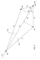
- FIG. 2 there is presented another illustration of the positioning system 10, showing the geometrical disposition of the positioning system operating in zone Z (zone Z is not shown in Fig. 2 ) and an object 100 located within zone Z.
- the portions of signal TS that are emitted by antenna 120 travels a slant distance R 1 , which is longer by ⁇ R comparing those portions emitted by antenna 130, that travel a distance R 2 .
- ⁇ t is the time delay between portions of the positioning signal emitted by the spaced-apart antennas 120 and 130, as received at point 100 (note that for simplicity, a delay D that characterized the operation of the phase difference estimator, and is a predefined and known parameter, is not included in relation (1));
- N is an integer indicating the number of cycles of signal TS along ⁇ R (for simplicity, the discussion relating to Fig. 2 will continue based on the assumption that N is known. The ambiguity of N is discussed further below, with reference to Fig. 5 ); and c is the speed of light.
- a surface CS is defined, which is the surface of a cone generated by angle ⁇ , onto which points 100, 120 and 130 are located. This provides information indicating the orientation of point 100 relative to points 120 and 130.
- the orientation of point 100 relative to points 120 and 130 could be determined using additional information, e.g. information gathered in a manner detailed below with reference to Fig. 3 , or elimination procedures known per-se in the field of interferometry (including, but not limited to the use of the assumed or measured height of point 100).
- a system 110 further includes a third antenna 150, located at a distance R 4 away from antenna 120.
- signal TS is generated by the common unit 140 and switched between the three spaced-apart antennas 120, 130 and 150.
- the positioning signal TS includes signal portions that are alternately transmitted by antennas 120, 130 and 150.
- ⁇ 1 and ⁇ 2 are determined with respect to antennas 120, 130 and 100; and ⁇ 2 is determined with respect to antennas 120, 150 (the other antenna) and 100. Consequently, two Surfaces, CS 1 (representing the surface of a cone onto which points 100, 120 and 130 are located) and CS 2 (representing the surface of a cone onto which points 100, 120 and 150 are located) are defined. CS 1 and CS 2 intersect with each other, and the intersection line represents the pointing vector PV (orientation) between antenna 120 and the unknown point 100 . In other words, by measuring parameters f and ⁇ of the returned signal, which indicate the phase differences between portions of the positioning signal as received by the transponder, the orientation of the transponder could be determined.
- the positioning signal TS transmitted by the base station 140 (switched between antennas 120 and 130), as picked up at point 100, carries information about the direction of point 100 relative to the base station.
- Object 100 is configured to return the positioning signal (signal RS ) to the base station and therefore the position information carried by signal RS is now available to the base station, allowing it to determine the orientation of the object relative thereto.
- RS may have a different frequency than signal TS.
- TOA/DTOA Time of Arrival/Time Difference of Arrival
- Figs. 4a-4c schematically illustrate antenna array configurations according to various embodiments of the invention.
- Fig. 4a schematically illustrates an antenna array 400 according to the embodiment of the invention illustrated in Fig. 2 .
- the antenna array 400 comprises two spaced-apart transmit antennas, (namely antennas 120 and 130, shown in Fig. 2 ).
- Antennas 120 and 130 are coupled to a common signal generating and switching unit 140.
- Unit 140 generates a periodic signal (e.g. a sinusoidal signal) and switches the signal between antennas 120 and 130.
- a periodic signal e.g. a sinusoidal signal
- the antennas are coupled to the switching unit 140 via substantially identical feed lines (note that non-identical feed lines could also be used, with appropriate means for compensation for consequent delays), such that the output of unit 140 feeds the antennas in a switched manner, thereby giving rise to a positioning signal which includes portions of signal transmitted alternately from the antennas.
- Fig. 4a allows for the determination of the orientation of point 100 relative to the positioning system in two dimensions only. This is most suitable for planar applications (e.g. when object 100, shown in Fig. 1 , travels a substantially planar path). If the altitude of object 100 is known. e.g. using other devices (e.g. an altimeter), then its three-dimensional orientation could be defined in a manner known per-se using the determination of the pointing vector PV between the platform and antenna 120 (shown in Fig. 2 ), in combination with the readings of the altimeter at point 100.
- other devices e.g. an altimeter
- An antenna array 410 according to another embodiment of the invention is shown in Fig. 4b .
- Array 410 comprises three antennas, 120, 130 and 150 which are coupled to a common generating and switching unit 145. This configuration relates to the embodiment of the invention shown in Fig. 3 , which allows the determination of the orientation of the object (pointing vector PV) in three dimensions.
- Array 420 comprises four antennas (120, 130, 150 and 170), coupled to a common generating and switching unit 145.
- the antenna array 420 is arranged in a tetrahedron form, in which antennas 120, 130 and 150 are located onto the same plane, and antenna 170 is located outside that plane.
- Zone Z the zone in which the positioning signal TS can be received.
- the resultant positioning system is substantially omni-directional. Note that the discussion above relating to Figs. 4a-4c focuses in the antenna array for transmission:
- another antenna e.g. element 125 shown in Fig. 1
- the discussion above did not include discussion regarding the ambiguity relating to the determination of parameter N, indicating the integer number of cycles of signal TS along ⁇ R.
- N the ambiguity of N is solved in the following manner, discussed with reference to Figs. 5 and 6 together with Fig. 2 :
- the positioning signal TS may include signal portions having a first frequency f 1 , and signal portions having a second frequency, f 2 .
- the signal portions having the frequency f 1 are switched between, and emitted by all the antennas at the antenna array (two antennas 120 and 130 in the example shown in Fig. 2 ), as well as those having the frequency f 2 . Therefore, a first phase difference ⁇ 1 corresponding to the first frequency f 1 , and a second phase difference ⁇ 2 , corresponding to the second frequency f 2 , could be measured.
- the difference between the detected values of ⁇ 1 and ⁇ 2 is used for determining N, in the following manner:
- Frequencies f 1 and f 2 are selected such that N 1 and N 2 , indicating the integer number of cycles of signal TS along ⁇ R, will follow the relation:
- N 1 (k) f 1 ⁇ ⁇ 1 + f 2 ⁇ ⁇ 2 / 2 ⁇ ⁇ ⁇ f 2 - f 1 + f 1 ⁇ k / f 2 - f 1
- N 1 is determined as the optimal solution of relation (7) (e.g. when the minimum of a truncN 1 or (1 - truncN 1 ) is achieved).
- the periodic signal includes two frequencies of a predefined difference (e.g.
- the predefined difference gives rise to a limited set of values for k, and therefore the value of N could easily be determined by measuring parameters f and ⁇ of signal portions of both frequencies (that is, f 1 , f 2 , ⁇ 1 and ⁇ 2 ).
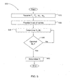
- Fig. 5 is a flow chart showing a sequence of operations 500 carried out for the determination of parameter N:
- k could be provided from a reference table according to the difference between f 1 and f 2 (e.g., for a 100MHz difference, the set of values for k includes the values 1, 2 and 3);
- the selected N 1 (k) is determined as parameter N.
- the positioning signal TS may include signal portions having a first frequency f 1 , and signal portions having a second frequency, f 2 .
- the portions transmitted by one antenna need not be identical in length to those transmitted by the other antenna/s.
- the timing and duration of the switching of the signal between the transmitting antennas can be changed along the transmission of the positioning signal.
- additional signal portions carrying additional information e.g. the identity of the base station, and more
- the periodic signal needs to be transmitted while being alternately switched between the antennas, thereby constituting the positioning signal.
- phase difference between portions of positioning signal alternately transmitted by the different antennas is affected by the geometrical arrangement of the antennas.
- the phase difference detected for positioning is derived by comparing a portion of the returned positioning signal RS with a delayed portion of the same returned positioning signal.
- Fig. 7 is a block diagram showing a positioning system 700 according to one embodiment of the invention.
- system 700 is presented as having a 'transmit' part - comprising an antenna array (e.g. antenna array of two antennas 120 and 130, as shown in Fig. 4a ) and a common generating and switching unit 140, all responsible for the transmission of the positioning signal TS; and a 'receive' part - comprising a receive antenna 125, a time and phase difference estimator 145 and a positioning utility 180, which is a processing hardware/software utility, responsible for receiving and analyzing the returned positioning signal RS.
- antenna array e.g. antenna array of two antennas 120 and 130, as shown in Fig. 4a
- a common generating and switching unit 140 all responsible for the transmission of the positioning signal TS
- a 'receive' part - comprising a receive antenna 125, a time and phase difference estimator 145 and a positioning utility 180, which is a processing hardware/software utility, responsible
- phase difference estimator 145 can be realized based on any devices and methods known in the art for estimating phase differences.
- phase difference estimator 145 may include a digital comparator for comparing a currently received portion of signal with a previously received portion of the same signal (a portion fed via a delay component, e.g. a FIFO (First In First Out) buffer providing a 0.5 ⁇ sec. delay).
- a delay component e.g. a FIFO (First In First Out) buffer providing a 0.5 ⁇ sec. delay
- the phase difference estimator 145 can be realized based on a Modulation-on-Pulse device, known in the art.
- Positioning utility 180 comprises, inter-alia, an f/ ⁇ determination module 185 for determining the frequency f and phase ⁇ of various portions of the received signal, N determination module 190 for determination of parameter N (see discussion above with reference to Fig. 5 ), and position determination module 195 for calculating the position of the transponder.
- Fig. 7 are Analog-to Digital converters, which may be required.
- Positioning system 700 could also comprise a ranging utility (not shown in Fig. 7 ) operable for determining the range of the transponder relative to the system based on TOA/DTOA measurements and comparisons of the transmitted and returned signals, or for receiving range information from an external source (e.g. external unit performing TOA/DTOA analysis).
- Position determination module 195 may also be configured for determining the position of the transponder based on the orientation and range of the transponder relative to the system.
- the receive antenna 125 could be integrated with one of the transmit antennas. Furthermore, all elements could be integrated to form a positioning device compact in size and weight. In addition, the operation of the generating and switching unit 145 could be controlled by the processing utility 180.
- System 700 is illustrated in Fig. 7 in a non-limiting manner as a stand-alone system. However, it should be understood that the system can be integrated with additional hardware and software without departing from the scope of the invention.
- the positioning system is integrated with a system for providing the object to be positioned with position-based information, e.g. navigation information.
- Fig. 8 illustrates a positioning method according to an embodiment of the invention, showing a sequence of operations 800 carried out by a positioning system in order to determine the position of an unknown transponder.
- the positioning method comprises the following operation:
- the periodic signal may include one frequency (parameter f as discussed with reference to Figs. 2 and 3 ), or may have portions having a first frequency and portions having a second frequency (parameters f 1 and f 2 , as discussed above with reference to Figs. 5 and 6 ).
- the transponder Transmitting the signal to the transponder and receiving a returned signal.
- the transponder receives a positioning signal that has portions of signal transmitted alternately by each of the spaced-apart antennas (two, three or more, as the case may be).
- the transponder returns the signal at the same - or at a different frequency, and the return signal carries phase differences between portions of signal transmitted by different antennas as received by the transponder (this is discussed above mainly with reference to Fig. 2 ).
- the positioning signal transmitted to the transponder includes portions of the first frequency alternately transmitted by all of the antennas, and portions of the second frequency alternately transmitted by all of the antennas (this is illustrated in Fig. 6 ).
- the returned signal therefore, carries-phase differences corresponding to the first and second frequencies.
- the phase difference estimator (element 145 shown in Fig. 7 ) measures the above mentioned phase differences (parameters f and ⁇ - or f 1 , f 2 , ⁇ 1 , ⁇ 2 are measured, as discussed with reference to Figs. 2 , 3 , 5 and 6 ).
- the positioning utility (element 180 shown in Fig. 7 ) determines the orientation of the transponder relative to the system. In case information about the range of the transponder relative to the positioning system is available (e.g. by TOA/DTOA comparison of the transmitted signal and returned signal, or from an external source), the position of the transponder can be easily determined based on method known per-se .
- Sequence of operations 800 may also comprise one or all of the following operations:
- the invention was described mainly with reference to a ground platform. It should be noted that the invention is also applicable for airborne and sea-borne vehicles, with the required alterations and modifications. The invention could also be realized as a hand-held mobile device.
- the present invention could be integrated with a cellular communication network, e.g. for supporting geographically-based services.
- a cellular communication network is formed as a grid of cells covering a service area.
- network components e.g. cell site or base station, including transmitting/receiving equipment
- serving the mobile communication devices currently located within the cell and communicating with other network components (e.g. other cell sites, central components, etc.).
- Each mobile communication device communicates in a timely manner with its cell site, receiving and returning a control signal, thereby providing the network with information indicating the current range between the mobile device and the serving cell site.
- the specific position (orientation) of the mobile device within a cell is unknown to the network. For example, as is clear, in light of the detailed discussion above, by proving a cell site having two antennas and switching the control signal therebetween, information about the direction of the mobile device relative to the cell site can be established.
- the present invention could be integrated with other positioning systems (e.g. GPS (Global Positioning system) or INS (Inertial Navigation System), in order to validate the readings of those other positioning systems and assess their accuracy. For example, by comparing the position of an object determined according to the invention with a GPS-based position, it is possible to determine if the GPS signal is jammed or deceived. By providing accurate positioning information, the present invention could also be used for correlating timed information between different and remote systems, and for calibrating INS devices.
- GPS Global Positioning system
- INS Inertial Navigation System
- the positioning system provides high precision position measurements.
- the precision is affected by the range of frequencies, and it is clear that at higher frequencies, better precision is yielded. However, in order to provide greater system range, lower frequencies are required. Note that while at the frequency range of about 1GHz, Line of Site (LOS) transmission is required; this limitation is decreased at lower frequencies.
- the precision is further affected by the geometry of the array of the antennas which are coupled to a common switch. Additional precision is achieved by averaging phase measurements over a period of time (e.g. over 1 msec.). System errors are minimal as there is no need to compensate for receiver errors and to correlate readings from different receivers.
- the positioning system provides high update rate.
- the update rate is affected by the width of the periodic signal as well as by the length of the switching cycle (i.e. the length of time needed for transmission of the periodic signal by all antennas in the antenna array). For example, by setting the width of a 1GHz periodic signal to 1 msec, and the length of the switching cycle to 4 msec, a 100KHz update rate is maintained. Note that high update rate provides better navigation precision and better signal-to-noise ratio, and consequently, larger coverage area.
- the positioning system according to the present invention is better protected against jamming.
- the positioning signal available to transponders located within the coverage area of the positioning system is stronger than the GPS signal available in most areas covered by the GPS system, and therefore stronger signal is required for jamming.
- the invention was described with reference to RF radiation, and mainly to RF radiation of frequencies of about 1Ghz. It should be noted that the invention is not limited by the exemplified frequencies, and could be employed along other portions of the radio spectrum as well as other electromagnetic radiation spectra. Furthermore, the invention is not limited to electromagnetic radiation and is applicable to any other form of propagating wave-borne energy, such as acoustic, ultrasonic, etc.
- positioning systems were described as stand-alone systems. It should be noted that a positioning system, according to the invention, could be integrated with other systems, e.g. other positioning systems, direction-finders, radar systems and many more, with the required alterations and modifications.
Landscapes
- Engineering & Computer Science (AREA)
- Radar, Positioning & Navigation (AREA)
- Remote Sensing (AREA)
- Physics & Mathematics (AREA)
- General Physics & Mathematics (AREA)
- Computer Networks & Wireless Communication (AREA)
- Position Fixing By Use Of Radio Waves (AREA)
- Radar Systems Or Details Thereof (AREA)
Claims (16)
- Système pour positionner un répéteur, le système comprenant un groupement d'antennes d'au moins deux antennes espacées (120, 130, 150, 170) couplées à une unité commune de génération et de commutation (140), ladite unité de génération et de commutation étant configurée pour générer un signal périodique (TS) et aiguiller ce signal parmi lesdites au moins deux antennes, en constituant un signal de positionnement transmis au répéteur ; le système comprenant un récepteur pour recevoir un signal renvoyé (RS) et un estimateur de différence de phase (145) couplé au récepteur et utilisable pour mesurer des différences de phases entre des segments du signal renvoyé ; le système comprenant en outre un utilitaire de positionnement (180) couplé audit estimateur de différence de phase et configuré pour déterminer la position du répéteur relativement au système de positionnement.
- Système selon la revendication 1, dans lequel la détermination de la position du répéteur inclut la détermination de la direction du répéteur relativement au système de positionnement.
- Système selon la revendication 1, dans lequel la détermination de la position du répéteur inclut la détermination de la distance du répéteur relativement au système de positionnement, en se fondant sur une comparaison d'instants d'arrivée (TOA) entre le signal de positionnement émis par le système et le signal renvoyé par le répéteur.
- Système selon la revendication 1, dans lequel la détermination de la position du répéteur inclut la détermination de la distance du répéteur relativement au système de positionnement, en se fondant sur des informations reçues depuis une source externe au système, concernant la distance du répéteur relativement au système.
- Système selon la revendication 1, dans lequel ledit signal périodique inclut des segments ayant une première fréquence et des segments ayant une seconde fréquence ; des segments ayant la même fréquence étant aiguillés parmi lesdites au moins deux antennes espacées.
- Système selon la revendication 5, dans lequel ladite première fréquence est dans la gamme d'environ 1 GHz ou plus et la seconde fréquence diffère de la première fréquence d'environ 1 MHz.
- Système selon l'une quelconque des revendications précédentes, dans lequel lesdites antennes espacées sont couplées à ladite unité de génération et de commutation par l'intermédiaire de lignes d'alimentation d'antennes sensiblement identiques.
- Système selon l'une quelconque des revendications précédentes, dans lequel ledit groupement d'antennes comprend quatre antennes disposées en tétraèdre.
- Système selon la revendication 1, configuré en outre, en se fondant sur la détermination de la position du répéteur, pour émettre les informations relatives à la position du répéteur.
- Procédé pour positionner un répéteur, le procédé comprenant les étapes consistant à : générer (810) un signal périodique et aiguiller le signal périodique parmi un groupement d'antenne d'au moins deux antennes espacées, de positions connues, couplées à une unité commune de génération et de commutation ; transmettre (820) le signal au répéteur et recevoir un signal renvoyé ; en se fondant sur des mesures de différences de phases entre des segments du signal renvoyé, déterminer (830) la direction du répéteur relativement au système, en permettant ainsi la détermination de la position du répéteur relativement au système de positionnement.
- Procédé selon la revendication 10, comprenant en outre l'étape consistant à :en se fondant sur une comparaison d'instants d'arrivée (TOA) entre le signal émis par le système et le signal renvoyé par le répéteur, déterminer la distance du répéteur relativement au système de positionnement.
- Procédé selon la revendication 10, comprenant en outre l'étape consistant à :recevoir depuis une source externe des informations concernant la distance durépéteur relativement au système de positionnement et déterminer la position du répéteur.
- Procédé selon la revendication 10, comprenant en outre l'étape consistant à :comparer la position du répéteur avec des informations de position sur la position du répéteur établies en utilisant des systèmes GPS (système de positionnement global) et/ou INS (système de navigation inertielle), en permettant ainsi d'évaluer la précision desdites informations de position.
- Procédé selon l'une quelconque des revendications 10 à 13, dans lequel ledit signal périodique inclut des segments ayant une première fréquence et des segments ayant une seconde fréquence ; des segments ayant la même fréquence étant aiguillés parmi lesdites au moins deux antennes espacées.
- Procédé selon l'une quelconque des revendications 10 à 14, dans lequel ladite première fréquence est dans la gamme d'environ 1 GHz ou plus et la seconde fréquence diffère de la première fréquence d'environ 1 MHz.
- Procédé selon l'une quelconque des revendications 10 à 15, dans lequel ledit groupement d'antennes comprend quatre antennes disposées en tétraèdre.
Applications Claiming Priority (2)
| Application Number | Priority Date | Filing Date | Title |
|---|---|---|---|
| IL169854A IL169854A (en) | 2005-07-25 | 2005-07-25 | System and method for finding receiver-transmitter location |
| PCT/IL2006/000861 WO2007013069A1 (fr) | 2005-07-25 | 2006-07-25 | Systeme et procede pour positionner un repeteur |
Publications (2)
| Publication Number | Publication Date |
|---|---|
| EP1910864A1 EP1910864A1 (fr) | 2008-04-16 |
| EP1910864B1 true EP1910864B1 (fr) | 2011-07-20 |
Family
ID=37033385
Family Applications (1)
| Application Number | Title | Priority Date | Filing Date |
|---|---|---|---|
| EP06766176A Not-in-force EP1910864B1 (fr) | 2005-07-25 | 2006-07-25 | Système et procédé pour positionner un répéteur |
Country Status (6)
| Country | Link |
|---|---|
| US (1) | US8229472B2 (fr) |
| EP (1) | EP1910864B1 (fr) |
| AT (1) | ATE517359T1 (fr) |
| ES (1) | ES2369996T3 (fr) |
| IL (1) | IL169854A (fr) |
| WO (1) | WO2007013069A1 (fr) |
Cited By (1)
| Publication number | Priority date | Publication date | Assignee | Title |
|---|---|---|---|---|
| US12461227B2 (en) * | 2022-01-18 | 2025-11-04 | Kapsch Trafficcom Ag | Method and apparatus for determining a lateral vehicle position |
Families Citing this family (26)
| Publication number | Priority date | Publication date | Assignee | Title |
|---|---|---|---|---|
| US7889133B2 (en) | 1999-03-05 | 2011-02-15 | Itt Manufacturing Enterprises, Inc. | Multilateration enhancements for noise and operations management |
| US7570214B2 (en) | 1999-03-05 | 2009-08-04 | Era Systems, Inc. | Method and apparatus for ADS-B validation, active and passive multilateration, and elliptical surviellance |
| US8446321B2 (en) | 1999-03-05 | 2013-05-21 | Omnipol A.S. | Deployable intelligence and tracking system for homeland security and search and rescue |
| US7777675B2 (en) | 1999-03-05 | 2010-08-17 | Era Systems Corporation | Deployable passive broadband aircraft tracking |
| US7739167B2 (en) | 1999-03-05 | 2010-06-15 | Era Systems Corporation | Automated management of airport revenues |
| US7612716B2 (en) | 1999-03-05 | 2009-11-03 | Era Systems Corporation | Correlation of flight track data with other data sources |
| US8203486B1 (en) | 1999-03-05 | 2012-06-19 | Omnipol A.S. | Transmitter independent techniques to extend the performance of passive coherent location |
| US7782256B2 (en) | 1999-03-05 | 2010-08-24 | Era Systems Corporation | Enhanced passive coherent location techniques to track and identify UAVs, UCAVs, MAVs, and other objects |
| US7667647B2 (en) | 1999-03-05 | 2010-02-23 | Era Systems Corporation | Extension of aircraft tracking and positive identification from movement areas into non-movement areas |
| US7908077B2 (en) | 2003-06-10 | 2011-03-15 | Itt Manufacturing Enterprises, Inc. | Land use compatibility planning software |
| IL169854A (en) | 2005-07-25 | 2013-11-28 | Elta Systems Ltd | System and method for finding receiver-transmitter location |
| IL169855A (en) * | 2005-07-25 | 2014-05-28 | Elta Systems Ltd | A system and method for locating a receiver location |
| US7965227B2 (en) | 2006-05-08 | 2011-06-21 | Era Systems, Inc. | Aircraft tracking using low cost tagging as a discriminator |
| FR2926891A1 (fr) * | 2008-01-30 | 2009-07-31 | Astrium Sas Soc Par Actions Si | Procede et systeme pour la determination d'angles de visee entre deux dispositifs |
| US20130088395A1 (en) * | 2010-06-19 | 2013-04-11 | Nokia Corporation | Method and apparatus for estimating direction of arrival |
| US20120223811A1 (en) * | 2011-03-03 | 2012-09-06 | Checkpoint Systems, Inc. | Multiple Antenna Localizing |
| EP3187893B1 (fr) | 2011-05-18 | 2022-07-06 | Lambda: 4 Entwicklungen GmbH | Procédé de détermination de l'emplacement d'un récepteur |
| DE202011051720U1 (de) * | 2011-10-21 | 2013-01-22 | Hanning & Kahl Gmbh & Co. Kg | Vorrichtung zur Übermittlung von ortsgebundenen Nachrichten von Fahrzeugen an eine ortsfeste Infrastruktur |
| US9001621B2 (en) | 2012-04-20 | 2015-04-07 | Symbol Technologies, Inc. | Dual frequency ultrasonic locationing system |
| TWI452322B (zh) * | 2012-08-17 | 2014-09-11 | Au Optronics Corp | 使用聲波測量物體空間位置的方法及系統 |
| US9702970B2 (en) * | 2013-08-30 | 2017-07-11 | Maxim Integrated Products, Inc. | Time of arrival delay cancellations |
| US9606224B2 (en) * | 2014-01-14 | 2017-03-28 | Alstom Transport Technologies | Systems and methods for vehicle position detection |
| EP3415946B1 (fr) * | 2017-06-13 | 2021-08-04 | Swiss Timing Ltd. | Procédé pour calculer une position d'un transpondeur dans une zone d'intérêt |
| EP3726241A1 (fr) * | 2019-04-19 | 2020-10-21 | Siemens Mobility GmbH | Procédé et système de localisation d'un objet |
| DE102020133788A1 (de) * | 2020-12-16 | 2022-06-23 | Sick Ag | Sicherheitssystem und ein Verfahren zur Lokalisierung |
| EP4202492A1 (fr) | 2021-12-23 | 2023-06-28 | Volvo Autonomous Solutions AB | Système de localisation de véhicule |
Family Cites Families (32)
| Publication number | Priority date | Publication date | Assignee | Title |
|---|---|---|---|---|
| US3808597A (en) * | 1968-03-14 | 1974-04-30 | Teledyne Inc | Iso-phase position determining system |
| GB1468016A (en) * | 1973-11-16 | 1977-03-23 | Decca Ltd | Phase comparison radio navigation systems |
| US3946385A (en) * | 1975-01-20 | 1976-03-23 | The United States Of America As Represented By The Secretary Of The Department Of Transportation | Interferometric navigation and guidance system |
| CA1050140A (fr) * | 1975-12-19 | 1979-03-06 | National Research Council Of Canada | Indicateur de position radio vlf |
| DE2715383C3 (de) * | 1977-04-06 | 1981-02-19 | Standard Elektrik Lorenz Ag, 7000 Stuttgart | Funknavigationsanlage |
| US4283726A (en) * | 1978-09-05 | 1981-08-11 | Lewis C. Spence | Dual frequency distance measuring system |
| DE2843253A1 (de) | 1978-10-04 | 1980-04-17 | Standard Elektrik Lorenz Ag | Navigationssystem zur richtungs- und entfernungsmessung |
| FR2481465A1 (fr) * | 1980-04-25 | 1981-10-30 | Trt Telecom Radio Electr | Procede et dispositif pour la determination precise d'azimut a partir de la mesure de plusieurs dephasages |
| SE442348B (sv) | 1984-07-04 | 1985-12-16 | Stiftelsen Inst Mikrovags | Forfarande och anordning for bestemning av inbordes lege mellan tva objekt |
| US5099245A (en) * | 1987-10-23 | 1992-03-24 | Hughes Aircraft Company | Vehicle location system accuracy enhancement for airborne vehicles |
| US4975710A (en) * | 1989-08-01 | 1990-12-04 | Baghdady Elie J | Methods and apparatus for direction of arrival measurement and radio navigation aids |
| US5084709A (en) * | 1990-05-17 | 1992-01-28 | Baghdady Elie J | Method and apparatus for radio location |
| US5126513A (en) * | 1991-05-10 | 1992-06-30 | U.S. Philips Corporation | Interactive display system |
| US5883598A (en) * | 1995-12-15 | 1999-03-16 | Signatron Technology Corporation | Position location system and method |
| US6270433B1 (en) | 1997-12-15 | 2001-08-07 | Toy Builders | Player position detection system |
| US6347229B1 (en) * | 1999-08-26 | 2002-02-12 | Intech 21, Inc. | Method for tracking the location of mobile units |
| US6489923B1 (en) * | 1999-09-16 | 2002-12-03 | Nortel Networks Limited | Position location method and apparatus for a mobile telecommunications system |
| US6590498B2 (en) * | 1999-10-19 | 2003-07-08 | Lucent Technologies Inc. | Method and apparatus for improving the interrogation range of an RF-Tag |
| CN1280640C (zh) * | 2000-06-05 | 2006-10-18 | Tc许可有限公司 | 确定调制的反向散射通信系统中应答器方向的方法和设备 |
| US6868073B1 (en) | 2000-06-06 | 2005-03-15 | Battelle Memorial Institute K1-53 | Distance/ranging by determination of RF phase delta |
| US7024331B2 (en) * | 2000-11-15 | 2006-04-04 | Scientific Generics Limited | Tag tracking |
| US6784826B2 (en) * | 2001-01-26 | 2004-08-31 | Tera Research Incorporated | Body motion tracking system |
| US6876326B2 (en) * | 2001-04-23 | 2005-04-05 | Itt Manufacturing Enterprises, Inc. | Method and apparatus for high-accuracy position location using search mode ranging techniques |
| US6700536B1 (en) * | 2001-10-25 | 2004-03-02 | Richard J. Wiegand | System and method for determining a direction of incident electromagnetic signals |
| FI111037B (fi) * | 2002-02-25 | 2003-05-15 | Nokia Corp | Menetelmä ja järjestelmä elektroniikkalaitteen sijainnin määrittämiseksi ja elektroniikkalaite |
| JP2003339070A (ja) * | 2002-05-21 | 2003-11-28 | Hitachi Ltd | 位置検出システムおよび携帯端末およびサーバ |
| WO2004002012A1 (fr) * | 2002-06-21 | 2003-12-31 | Siemens Aktiengesellschaft | Determination de la position d'un utilisateur dans un systeme de communication radio a diversite d'emission |
| US6914559B2 (en) * | 2003-09-22 | 2005-07-05 | Northrop Grumman Corporation | Direction finding method and system using digital directional correlators |
| US7260408B2 (en) * | 2004-02-20 | 2007-08-21 | Airespace, Inc. | Wireless node location mechanism using antenna pattern diversity to enhance accuracy of location estimates |
| US7778651B2 (en) * | 2005-02-16 | 2010-08-17 | Harris Corporation | Wireless network range estimation and associated methods |
| IL169854A (en) | 2005-07-25 | 2013-11-28 | Elta Systems Ltd | System and method for finding receiver-transmitter location |
| IL169855A (en) * | 2005-07-25 | 2014-05-28 | Elta Systems Ltd | A system and method for locating a receiver location |
-
2005
- 2005-07-25 IL IL169854A patent/IL169854A/en active IP Right Grant
-
2006
- 2006-07-25 US US11/989,478 patent/US8229472B2/en not_active Expired - Fee Related
- 2006-07-25 ES ES06766176T patent/ES2369996T3/es active Active
- 2006-07-25 WO PCT/IL2006/000861 patent/WO2007013069A1/fr not_active Ceased
- 2006-07-25 AT AT06766176T patent/ATE517359T1/de not_active IP Right Cessation
- 2006-07-25 EP EP06766176A patent/EP1910864B1/fr not_active Not-in-force
Cited By (1)
| Publication number | Priority date | Publication date | Assignee | Title |
|---|---|---|---|---|
| US12461227B2 (en) * | 2022-01-18 | 2025-11-04 | Kapsch Trafficcom Ag | Method and apparatus for determining a lateral vehicle position |
Also Published As
| Publication number | Publication date |
|---|---|
| IL169854A (en) | 2013-11-28 |
| US20100001896A1 (en) | 2010-01-07 |
| WO2007013069A1 (fr) | 2007-02-01 |
| US8229472B2 (en) | 2012-07-24 |
| ES2369996T3 (es) | 2011-12-09 |
| EP1910864A1 (fr) | 2008-04-16 |
| ATE517359T1 (de) | 2011-08-15 |
Similar Documents
| Publication | Publication Date | Title |
|---|---|---|
| EP1910864B1 (fr) | Système et procédé pour positionner un répéteur | |
| Jami et al. | Comparison of methods of locating and tracking cellular mobiles | |
| US8416071B2 (en) | Relative location determination of mobile sensor nodes | |
| US8120526B2 (en) | Methods, apparatuses and systems for locating non-cooperative objects | |
| US11092665B2 (en) | High frequency geo-location methods and systems | |
| EP1910860B1 (fr) | Système de positionnement et procédé | |
| JP2021509171A (ja) | 第2のデバイスの既知のロケーションに基づいて第1のデバイスのロケーションを求めるミリ波通信システム及び方法 | |
| US5615175A (en) | Passive direction finding device | |
| EP2449626A1 (fr) | Antenne réseau à commande de phase conformée à auto-étalonnage | |
| KR100904681B1 (ko) | 하나의 무선수신국을 이용한 무선발신기의 위치측정 방법및 장치 | |
| RU2275649C2 (ru) | Способ местоопределения источников радиоизлучения и пассивная радиолокационная станция, используемая при реализации этого способа | |
| CN101156077A (zh) | 具有稀疏天线阵列的定位系统 | |
| Zhang et al. | Principles and techniques of RFID positioning | |
| RU2506605C2 (ru) | Дальномерный способ и устройство определения координат источника радиоизлучения | |
| JPH0534447A (ja) | マルチスタテイツクレーダ方式 | |
| KR102287852B1 (ko) | 무인항공기용 전파측위시스템 및 무인항공기용 항행방법 | |
| JP2009270863A (ja) | バイスタティックレーダ装置 | |
| Hua et al. | Joint TDOA-DOA localization scheme for passive coherent location systems | |
| Fabrizio | Geolocation of HF skywave radar signals using multipath in an unknown ionosphere | |
| RU38509U1 (ru) | Система многопозиционного определения координат загоризонтных объектов по излучениям их радиолокационных станций | |
| JP2000147099A (ja) | 瞬時パッシブ距離測定装置 | |
| JP2982751B2 (ja) | 位置標定方法及び装置 | |
| US10390581B1 (en) | Radio frequency head tracker | |
| Olyazadeh | Least Square Approach on Indoor Positioning Measurement Techniques | |
| JP2004093341A (ja) | 電波測位装置 |
Legal Events
| Date | Code | Title | Description |
|---|---|---|---|
| PUAI | Public reference made under article 153(3) epc to a published international application that has entered the european phase |
Free format text: ORIGINAL CODE: 0009012 |
|
| 17P | Request for examination filed |
Effective date: 20080214 |
|
| AK | Designated contracting states |
Kind code of ref document: A1 Designated state(s): AT BE BG CH CY CZ DE DK EE ES FI FR GB GR HU IE IS IT LI LT LU LV MC NL PL PT RO SE SI SK TR |
|
| 17Q | First examination report despatched |
Effective date: 20080617 |
|
| RIN1 | Information on inventor provided before grant (corrected) |
Inventor name: FRIEAIZEN, MOSHE |
|
| GRAP | Despatch of communication of intention to grant a patent |
Free format text: ORIGINAL CODE: EPIDOSNIGR1 |
|
| DAX | Request for extension of the european patent (deleted) | ||
| RIN1 | Information on inventor provided before grant (corrected) |
Inventor name: FRIEAIZEN, MOSHE |
|
| GRAS | Grant fee paid |
Free format text: ORIGINAL CODE: EPIDOSNIGR3 |
|
| GRAA | (expected) grant |
Free format text: ORIGINAL CODE: 0009210 |
|
| AK | Designated contracting states |
Kind code of ref document: B1 Designated state(s): AT BE BG CH CY CZ DE DK EE ES FI FR GB GR HU IE IS IT LI LT LU LV MC NL PL PT RO SE SI SK TR |
|
| REG | Reference to a national code |
Ref country code: GB Ref legal event code: FG4D |
|
| REG | Reference to a national code |
Ref country code: CH Ref legal event code: EP |
|
| RIN2 | Information on inventor provided after grant (corrected) |
Inventor name: FIREAIZEN, MOSHE |
|
| REG | Reference to a national code |
Ref country code: DE Ref legal event code: R096 Ref document number: 602006023201 Country of ref document: DE Effective date: 20110908 |
|
| REG | Reference to a national code |
Ref country code: NL Ref legal event code: T3 |
|
| REG | Reference to a national code |
Ref country code: ES Ref legal event code: FG2A Ref document number: 2369996 Country of ref document: ES Kind code of ref document: T3 Effective date: 20111209 |
|
| REG | Reference to a national code |
Ref country code: AT Ref legal event code: MK05 Ref document number: 517359 Country of ref document: AT Kind code of ref document: T Effective date: 20110720 |
|
| PG25 | Lapsed in a contracting state [announced via postgrant information from national office to epo] |
Ref country code: PT Free format text: LAPSE BECAUSE OF FAILURE TO SUBMIT A TRANSLATION OF THE DESCRIPTION OR TO PAY THE FEE WITHIN THE PRESCRIBED TIME-LIMIT Effective date: 20111121 Ref country code: IS Free format text: LAPSE BECAUSE OF FAILURE TO SUBMIT A TRANSLATION OF THE DESCRIPTION OR TO PAY THE FEE WITHIN THE PRESCRIBED TIME-LIMIT Effective date: 20111120 Ref country code: LT Free format text: LAPSE BECAUSE OF FAILURE TO SUBMIT A TRANSLATION OF THE DESCRIPTION OR TO PAY THE FEE WITHIN THE PRESCRIBED TIME-LIMIT Effective date: 20110720 Ref country code: SE Free format text: LAPSE BECAUSE OF FAILURE TO SUBMIT A TRANSLATION OF THE DESCRIPTION OR TO PAY THE FEE WITHIN THE PRESCRIBED TIME-LIMIT Effective date: 20110720 Ref country code: BE Free format text: LAPSE BECAUSE OF FAILURE TO SUBMIT A TRANSLATION OF THE DESCRIPTION OR TO PAY THE FEE WITHIN THE PRESCRIBED TIME-LIMIT Effective date: 20110720 Ref country code: FI Free format text: LAPSE BECAUSE OF FAILURE TO SUBMIT A TRANSLATION OF THE DESCRIPTION OR TO PAY THE FEE WITHIN THE PRESCRIBED TIME-LIMIT Effective date: 20110720 |
|
| PG25 | Lapsed in a contracting state [announced via postgrant information from national office to epo] |
Ref country code: GR Free format text: LAPSE BECAUSE OF FAILURE TO SUBMIT A TRANSLATION OF THE DESCRIPTION OR TO PAY THE FEE WITHIN THE PRESCRIBED TIME-LIMIT Effective date: 20111021 Ref country code: PL Free format text: LAPSE BECAUSE OF FAILURE TO SUBMIT A TRANSLATION OF THE DESCRIPTION OR TO PAY THE FEE WITHIN THE PRESCRIBED TIME-LIMIT Effective date: 20110720 Ref country code: AT Free format text: LAPSE BECAUSE OF FAILURE TO SUBMIT A TRANSLATION OF THE DESCRIPTION OR TO PAY THE FEE WITHIN THE PRESCRIBED TIME-LIMIT Effective date: 20110720 Ref country code: SI Free format text: LAPSE BECAUSE OF FAILURE TO SUBMIT A TRANSLATION OF THE DESCRIPTION OR TO PAY THE FEE WITHIN THE PRESCRIBED TIME-LIMIT Effective date: 20110720 Ref country code: LV Free format text: LAPSE BECAUSE OF FAILURE TO SUBMIT A TRANSLATION OF THE DESCRIPTION OR TO PAY THE FEE WITHIN THE PRESCRIBED TIME-LIMIT Effective date: 20110720 Ref country code: MC Free format text: LAPSE BECAUSE OF NON-PAYMENT OF DUE FEES Effective date: 20110731 Ref country code: CY Free format text: LAPSE BECAUSE OF FAILURE TO SUBMIT A TRANSLATION OF THE DESCRIPTION OR TO PAY THE FEE WITHIN THE PRESCRIBED TIME-LIMIT Effective date: 20110720 |
|
| REG | Reference to a national code |
Ref country code: CH Ref legal event code: PL |
|
| REG | Reference to a national code |
Ref country code: IE Ref legal event code: MM4A |
|
| PG25 | Lapsed in a contracting state [announced via postgrant information from national office to epo] |
Ref country code: CZ Free format text: LAPSE BECAUSE OF FAILURE TO SUBMIT A TRANSLATION OF THE DESCRIPTION OR TO PAY THE FEE WITHIN THE PRESCRIBED TIME-LIMIT Effective date: 20110720 Ref country code: SK Free format text: LAPSE BECAUSE OF FAILURE TO SUBMIT A TRANSLATION OF THE DESCRIPTION OR TO PAY THE FEE WITHIN THE PRESCRIBED TIME-LIMIT Effective date: 20110720 Ref country code: CH Free format text: LAPSE BECAUSE OF NON-PAYMENT OF DUE FEES Effective date: 20110731 Ref country code: LI Free format text: LAPSE BECAUSE OF NON-PAYMENT OF DUE FEES Effective date: 20110731 |
|
| PLBE | No opposition filed within time limit |
Free format text: ORIGINAL CODE: 0009261 |
|
| STAA | Information on the status of an ep patent application or granted ep patent |
Free format text: STATUS: NO OPPOSITION FILED WITHIN TIME LIMIT |
|
| PG25 | Lapsed in a contracting state [announced via postgrant information from national office to epo] |
Ref country code: RO Free format text: LAPSE BECAUSE OF FAILURE TO SUBMIT A TRANSLATION OF THE DESCRIPTION OR TO PAY THE FEE WITHIN THE PRESCRIBED TIME-LIMIT Effective date: 20110720 Ref country code: EE Free format text: LAPSE BECAUSE OF FAILURE TO SUBMIT A TRANSLATION OF THE DESCRIPTION OR TO PAY THE FEE WITHIN THE PRESCRIBED TIME-LIMIT Effective date: 20110720 |
|
| 26N | No opposition filed |
Effective date: 20120423 |
|
| PG25 | Lapsed in a contracting state [announced via postgrant information from national office to epo] |
Ref country code: DK Free format text: LAPSE BECAUSE OF FAILURE TO SUBMIT A TRANSLATION OF THE DESCRIPTION OR TO PAY THE FEE WITHIN THE PRESCRIBED TIME-LIMIT Effective date: 20110720 |
|
| PG25 | Lapsed in a contracting state [announced via postgrant information from national office to epo] |
Ref country code: IE Free format text: LAPSE BECAUSE OF NON-PAYMENT OF DUE FEES Effective date: 20110725 |
|
| REG | Reference to a national code |
Ref country code: DE Ref legal event code: R097 Ref document number: 602006023201 Country of ref document: DE Effective date: 20120423 |
|
| PG25 | Lapsed in a contracting state [announced via postgrant information from national office to epo] |
Ref country code: LU Free format text: LAPSE BECAUSE OF NON-PAYMENT OF DUE FEES Effective date: 20110725 |
|
| PG25 | Lapsed in a contracting state [announced via postgrant information from national office to epo] |
Ref country code: BG Free format text: LAPSE BECAUSE OF FAILURE TO SUBMIT A TRANSLATION OF THE DESCRIPTION OR TO PAY THE FEE WITHIN THE PRESCRIBED TIME-LIMIT Effective date: 20111020 |
|
| PG25 | Lapsed in a contracting state [announced via postgrant information from national office to epo] |
Ref country code: TR Free format text: LAPSE BECAUSE OF FAILURE TO SUBMIT A TRANSLATION OF THE DESCRIPTION OR TO PAY THE FEE WITHIN THE PRESCRIBED TIME-LIMIT Effective date: 20110720 |
|
| PG25 | Lapsed in a contracting state [announced via postgrant information from national office to epo] |
Ref country code: HU Free format text: LAPSE BECAUSE OF FAILURE TO SUBMIT A TRANSLATION OF THE DESCRIPTION OR TO PAY THE FEE WITHIN THE PRESCRIBED TIME-LIMIT Effective date: 20110720 |
|
| PGFP | Annual fee paid to national office [announced via postgrant information from national office to epo] |
Ref country code: NL Payment date: 20150825 Year of fee payment: 10 |
|
| PGFP | Annual fee paid to national office [announced via postgrant information from national office to epo] |
Ref country code: ES Payment date: 20150828 Year of fee payment: 10 |
|
| PGFP | Annual fee paid to national office [announced via postgrant information from national office to epo] |
Ref country code: IT Payment date: 20150825 Year of fee payment: 10 |
|
| REG | Reference to a national code |
Ref country code: FR Ref legal event code: PLFP Year of fee payment: 11 |
|
| REG | Reference to a national code |
Ref country code: NL Ref legal event code: MM Effective date: 20160801 |
|
| PG25 | Lapsed in a contracting state [announced via postgrant information from national office to epo] |
Ref country code: NL Free format text: LAPSE BECAUSE OF NON-PAYMENT OF DUE FEES Effective date: 20160801 |
|
| REG | Reference to a national code |
Ref country code: FR Ref legal event code: PLFP Year of fee payment: 12 |
|
| PG25 | Lapsed in a contracting state [announced via postgrant information from national office to epo] |
Ref country code: IT Free format text: LAPSE BECAUSE OF NON-PAYMENT OF DUE FEES Effective date: 20160725 |
|
| PG25 | Lapsed in a contracting state [announced via postgrant information from national office to epo] |
Ref country code: ES Free format text: LAPSE BECAUSE OF NON-PAYMENT OF DUE FEES Effective date: 20160726 |
|
| REG | Reference to a national code |
Ref country code: FR Ref legal event code: PLFP Year of fee payment: 13 |
|
| REG | Reference to a national code |
Ref country code: ES Ref legal event code: FD2A Effective date: 20181203 |
|
| PGFP | Annual fee paid to national office [announced via postgrant information from national office to epo] |
Ref country code: DE Payment date: 20180928 Year of fee payment: 13 |
|
| REG | Reference to a national code |
Ref country code: DE Ref legal event code: R119 Ref document number: 602006023201 Country of ref document: DE |
|
| PG25 | Lapsed in a contracting state [announced via postgrant information from national office to epo] |
Ref country code: DE Free format text: LAPSE BECAUSE OF NON-PAYMENT OF DUE FEES Effective date: 20200201 |
|
| PGFP | Annual fee paid to national office [announced via postgrant information from national office to epo] |
Ref country code: FR Payment date: 20200728 Year of fee payment: 15 Ref country code: GB Payment date: 20200724 Year of fee payment: 15 |
|
| GBPC | Gb: european patent ceased through non-payment of renewal fee |
Effective date: 20210725 |
|
| PG25 | Lapsed in a contracting state [announced via postgrant information from national office to epo] |
Ref country code: GB Free format text: LAPSE BECAUSE OF NON-PAYMENT OF DUE FEES Effective date: 20210725 |
|
| PG25 | Lapsed in a contracting state [announced via postgrant information from national office to epo] |
Ref country code: FR Free format text: LAPSE BECAUSE OF NON-PAYMENT OF DUE FEES Effective date: 20210731 |