EP1916104B2 - Appareil d'alimentation en liquide - Google Patents
Appareil d'alimentation en liquide Download PDFInfo
- Publication number
- EP1916104B2 EP1916104B2 EP07020523.2A EP07020523A EP1916104B2 EP 1916104 B2 EP1916104 B2 EP 1916104B2 EP 07020523 A EP07020523 A EP 07020523A EP 1916104 B2 EP1916104 B2 EP 1916104B2
- Authority
- EP
- European Patent Office
- Prior art keywords
- liquid
- squeegee
- liquid supply
- supply apparatus
- plate material
- Prior art date
- Legal status (The legal status is an assumption and is not a legal conclusion. Google has not performed a legal analysis and makes no representation as to the accuracy of the status listed.)
- Active
Links
Images




Classifications
-
- B—PERFORMING OPERATIONS; TRANSPORTING
- B41—PRINTING; LINING MACHINES; TYPEWRITERS; STAMPS
- B41F—PRINTING MACHINES OR PRESSES
- B41F9/00—Rotary intaglio printing presses
- B41F9/06—Details
- B41F9/061—Inking devices
-
- B—PERFORMING OPERATIONS; TRANSPORTING
- B41—PRINTING; LINING MACHINES; TYPEWRITERS; STAMPS
- B41F—PRINTING MACHINES OR PRESSES
- B41F11/00—Rotary presses or machines having forme cylinders carrying a plurality of printing surfaces, or for performing letterpress, lithographic, or intaglio processes selectively or in combination
- B41F11/02—Rotary presses or machines having forme cylinders carrying a plurality of printing surfaces, or for performing letterpress, lithographic, or intaglio processes selectively or in combination for securities
-
- B—PERFORMING OPERATIONS; TRANSPORTING
- B41—PRINTING; LINING MACHINES; TYPEWRITERS; STAMPS
- B41F—PRINTING MACHINES OR PRESSES
- B41F15/00—Screen printers
- B41F15/14—Details
- B41F15/40—Inking units
- B41F15/42—Inking units comprising squeegees or doctors
-
- B—PERFORMING OPERATIONS; TRANSPORTING
- B41—PRINTING; LINING MACHINES; TYPEWRITERS; STAMPS
- B41F—PRINTING MACHINES OR PRESSES
- B41F9/00—Rotary intaglio printing presses
- B41F9/02—Rotary intaglio printing presses for multicolour printing
- B41F9/021—Sheet printing presses
-
- B—PERFORMING OPERATIONS; TRANSPORTING
- B41—PRINTING; LINING MACHINES; TYPEWRITERS; STAMPS
- B41F—PRINTING MACHINES OR PRESSES
- B41F9/00—Rotary intaglio printing presses
- B41F9/02—Rotary intaglio printing presses for multicolour printing
- B41F9/023—Web printing presses
Definitions
- This invention relates to a liquid supply apparatus preferred when used in a printing press, which can perform rotary screen printing or coating, or in a coating machine.
- Patent Document 1 Japanese Unexamined Patent Publication No. 1999-188852
- Patent Document 2 Japanese Unexamined Patent Publication No. 2000-127351
- the printing press disclosed in Patent Document 1 includes an impression cylinder, an intaglio cylinder in contact with the impression cylinder, a blanket cylinder in contact with the intaglio cylinder, a plurality of pattern rollers in contact with the blanket cylinder, a plurality of first ink supply means for supplying inks to the pattern rollers, and a second ink supply means for supplying ink to the blanket cylinder with the use of a rotary screen.
- the rotary screen contacts the blanket cylinder via a rubber roller.
- the printing press disclosed in Patent Document 2 is an intaglio printing press including a plate cylinder having an intaglio mounted on a circumferential surface thereof, an impression cylinder in contact with the plate cylinder, an ink collecting cylinder in contact with the plate cylinder and having a blanket mounted on a circumferential surface thereof, a first ink supply means for supplying ink to the blanket of the ink collecting cylinder, a second ink supply means in contact with the plate cylinder for supplying ink to the intaglio, and a wiping roller in contact with the plate cylinder, the second ink supply means being furnished with a rotary screen.
- the rotary screen contacts the plate cylinder via a rubber roller.
- EP 1 602 483 A1 discloses an intaglio printing machine for sheets of documents, such as securities, bank-notes, cheques, ID, passports and other similar documents.
- the printing machine comprises at least a plate cylinder, a first inking unit, an impression cylinder and a wiping device for wiping the ink on the surface of the printing plates which are supported by the plate cylinder.
- US 3,844,213 A discloses a method of silk screen printing wherein a conventional rotary screen is provided with a smooth metal squeegee rod which is used to provide a force for forcing ink through the holes patterned screen.
- the present invention has been accomplished in light of the above-described problem. It is an object of the invention to provide a liquid supply apparatus which can continuously supply an adequate amount of liquid to the small hole group in the plate material.
- An aspect of the present invention is a liquid supply apparatus including a plate cylinder comprising a plate material, which has a small hole group for liquid supply formed in a circumferential surface of the plate material and which is supported rotatably, and a squeegee contacting an inner peripheral surface of the plate material, a rotating body supported rotatably to oppose an outer peripheral surface of the plate material at a position where the squeegee contacts the inner peripheral surface of the plate material, and a material to be supplied with a liquid, the material being supplied with the liquid, which has been stored within the plate material, by the squeegee via the small hole group of the plate material, the liquid supply apparatus comprising liquid guide means for guiding a surplus of the liquid, which is not supplied to the small hole group of the plate material by the squeegee, to the small hole group of the plate material.
- the liquid guide means collects the liquid, which does not correspond to the small hole group, and guides the collected liquid to a position corresponding to the small hole group.
- the liquid guide means does not guide the liquid to a position which does not correspond to the small hole group.
- the plate material may have a plurality of the small hole groups with predetermined spacing provided in a cylinder axis direction of the plate cylinder, and the liquid guide means may have a plurality of guide portions, the guide portions facing and corresponding to the small hole groups.
- the liquid guide means may be a plurality of guide grooves disposed at spaced locations in a cylinder axis direction of the plate cylinder.
- the liquid guide means may be guide passages formed between a plurality of weirs disposed at spaced locations in a cylinder axis direction of the plate cylinder.
- the liquid guide means may have a liquid reservoir for recovering the liquid flowing downward on the squeegee, and a liquid discharge hole bored in the liquid reservoir.
- the liquid guide means may have a liquid reservoir for recovering the liquid flowing downward on the squeegee, a storage tank into which the liquid accumulated in the liquid reservoir is discharged, and a liquid supply hole for supplying the liquid stored in the storage tank to the small hole group.
- the liquid reservoir may be a recovery pan provided below the squeegee.
- the liquid reservoir may be integrally formed in a fixing member for the squeegee.
- the liquid reservoir may be formed on a holding plate for the squeegee.
- the liquid reservoir and the storage tank may be connected by piping, and the liquid supply hole and the storage tank may be connected by piping.
- the liquid supply apparatus may further comprise a pump for supplying the liquid within the storage tank to the small hole group through the liquid supply hole.
- the liquid may be dropped by the liquid guide means onto a site of the plate material which is upstream, in a rotating direction of the plate material, of the position where the squeegee contacts the inner peripheral surface of the plate material.
- the squeegee may contact the inner peripheral surface of an upper portion of the plate material.
- the plate cylinder may be provided below the rotating body.
- the liquid supply apparatus may further comprise a sensor for detecting the surplus of the liquid, which is not supplied to the small hole group of the plate material by the squeegee, and liquid supply means for supplying the liquid to the inner peripheral surface of the plate material, and the liquid supply means may be controlled in response to an output of the sensor upon detection.
- the guide grooves may be formed in a squeegee holding plate for supporting the squeegee on a fixing member.
- the surplus liquid can be supplied to the small hole group of the plate material by the liquid guide means reliably in a sufficient amount. Hence, the occurrence of nonuniformity in printing, for example, can be avoided to prevent an increase in a waste of paper.
- Fig. 1A is an enlarged view of a rotary screen printing unit showing Embodiment 1 of the present invention.
- Fig. 1B is a configuration drawing of the interior of a rotary screen.
- Fig. 2 is a schematic configuration drawing of an intaglio printing press.
- a sheet feeder 10 bearing sheets (materials to be supplied with a liquid) W communicates with a feedboard 11 which receives the sheets W fed, one by one, from the top of a sheet pile by a sucker mechanism of the sheet feeder 10.
- a swing arm shaft pregripper 12 which grips the sheet W on the feedboard 11 and swings, is disposed on the feedboard 11.
- the swing arm shaft pregripper 12 communicates with an impression cylinder 14 via a transfer cylinder 13, the impression cylinder 14 having a plurality of (three in the illustrated embodiment) grippers (gripper devices) 14a disposed thereon with equal spacing in the circumferential direction.
- the transfer cylinder 13 is provided with grippers (gripper devices) similar to those of the impression cylinder 14.
- the impression cylinder 14 is in contact with a plate cylinder 15 which can be mounted with a plurality of intaglios along the circumferential direction of the plate cylinder 15.
- the intaglio of the plate cylinder 15 is in contact with an ink collecting cylinder 16 which can be mounted with a plurality of rubber blankets along the circumferential direction of the ink collecting cylinder 16.
- the ink collecting cylinder 16 is in contact with a plurality of (four in the illustrated embodiment) chablon rollers 17 arranged in the circumferential direction of the ink collecting cylinder 16. These chablon rollers 17 are each in contact with an ink fountain 20 via an ink fountain roller 19 and an intermediate roller 18, the ink fountain 20 being filled with conventional ink for printing a main design.
- the plate cylinder 15 is in contact with a rotary screen (stencil printingplate cylinder) 22 via a rubber roller (rotating body) 21, the rotary screen 22 being filled interiorly with special ink (liquid) such as OVI (optical variable ink) for printing a design for counterfeit deterrence.
- a rotary screen stencil printingplate cylinder
- a rubber roller rotating body
- OVI optical variable ink
- the rotary screen 22 comprises a hollow cylinder 31 which is a thin screen (a plate material made of stainless steel, nickel or the like) formed in a cylindrical shape and etched with a small hole group 30 corresponding to a pattern.
- the hollow cylinder 31 is rotatably supported by the frames.
- the small hole group 30 is illustrated as one circle.
- the small hole groups 30 are formed at many locations in correspondence with pattern forming portions of the hollow cylinder 31.
- a surplus of special ink which occurs between the squeegee 35 and a site of the hollow cylinder 31 upstream, in the rotating direction of the rotary screen 22, of the position where the squeegee 35 contacts the hollow cylinder 31, can be supplied by a liquid guide means (to be described later) to the small hole groups 30 of the hollow cylinder 31 formed upstream, in the rotating direction of the rotary screen 22, of the position where the rotary screen 22 opposes the rubber roller 21.
- a plurality of guide grooves 36 are formed in the upper surface of the squeegee holding plate 33 at predetermined intervals in the cylinder axis direction of the rotary screen 22.
- the positions of formation of these guide grooves 36 correspond to the positions of the small hole groups 30 in the hollow cylinder 31 in the cylinder axis direction of the rotary screen 22.
- a pump 38 To the interior of the hollow cylinder 31, special ink stored in a storage tank 37 is supplied via a pump 38 by a necessary amount in case of necessity.
- the pump 38 is drivingly controlled by a controller (not shown) in response to a detection signal of a liquid level sensor 39.
- reference numerals 29a and 29b denote ink guides for lateral squeegee leakage prevention which are secured to the fixing bar 32.
- the sheets W which have been fed, one by one, from the sheet feeder 10 onto the feedboard 11, are transferred from the swing arm shaft pregripper 12 to the grippers 14a of the impression cylinder 14 via the transfer cylinder 13, and transported while being gripped by the grippers 14a.
- conventional inks are supplied from within the ink fountains 20 to the chablon rollers 17 via the ink fountain rollers 19 and the intermediate rollers 18, then supplied to the ink collecting cylinder 16, and then supplied in a lump to the intaglio of the plate cylinder 15.
- special ink is directly supplied from within the rotary screen 22 to the intaglio of the plate cylinder 15 via the rubber roller 21 by the constant amount at each feeding in the predetermined pattern. These inks have their surplus amounts removed by a wiping roller 23, and are then transferred to the sheet W passed on to the impression cylinder 14 for printing.
- the printed sheet W is transported by a delivery chain 26 via a delivery cylinder 25 for delivery.
- the guide grooves 36 are formed in the upper surface of the squeegee holding plate 33, but the guide grooves 36 may be formed in the lower surface of the squeegee holding plate 33. Alternatively, a member provided with the guide grooves 36 may be separately formed, and annexed to the squeegee holding plate 33.
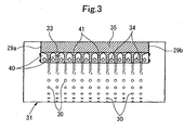
- Fig. 3 is a configuration drawing of the interior of a rotary screen showing Embodiment 2 of the present invention.
- Embodiment 1 This is an embodiment in which instead of the guide grooves 36 in Embodiment 1, a plurality of weirs 40 are disposed on the upper surface (optionally, lower surface) of the squeegee holding plate 33 at predetermined intervals in the cylinder axis direction of the rotary screen 22 to use gaps between the adjacent weirs 40 as guide passages 41 (liquid guide means) for the special ink.
- Fig. 4A is an enlarged view of a rotary screen printing unit showing Embodiment 3 of the present invention.
- Fig. 4B is a configuration drawing of the interior of a rotary screen.
- a recovery pan (liquid reservoir) 42 for recovering special ink flowing downward on the squeegee 35 is provided below the squeegee 35, and a plurality of ink discharge holes (liquid discharge holes) 42a are bored in a bottom wall portion of the recovery pan 42 in correspondence with the small hole groups 30 of the hollow cylinder 31 so that the recovery pan 42 and the ink discharge holes 42a serve as a liquid guide means.
- a liquid level sensor 39 is provided inside the recovery pan 42.
- Fig. 5A is an enlarged view of a rotary screen printing unit showing Embodiment 4 of the present invention.
- Fig. 5B is a configuration drawing of the interior of a rotary screen.
- ink supply holes (liquid supply holes) 45a are bored in the ink supply pipe 45 in correspondence with the small hole groups 30 of the hollow cylinder 31.
- a bottom wall portion of the liquid reservoir 32a having the semicircular cross section is inclined downwardly toward the ink discharge hole 43.
- An ink recovery pump 46 is interposed in the piping 44 connecting the ink discharge hole 43 and the storage tank 37, and an ink supply pump 48 is interposed in piping 47 connecting the storage tank 37 and the ink supply pipe 45.
- Embodiment 1 the same actions and effects as those in Embodiment 1 are obtained.
- special ink which has flowed down onto the liquid reservoir 32a from the squeegee 35, is recovered once into the storage tank 37 without being supplied, unchanged, to the small hole groups 30 of the hollow cylinder 31.
- this method is effective for printing with ink always having constant properties can be obtained. That is, if it is necessary to keep the density, viscosity, temperature, etc. of ink constant, it suffices to provide the storage tank 37 with a device suitable for attaining the desired purpose.
- Fig. 6A is an enlarged view of a rotary screen printing unit showing Embodiment 5 of the present invention.
- Fig. 6B is a configuration drawing of the interior of a rotary screen.
- Embodiment 4 This is an embodiment in which instead of the liquid reservoir 32a in Embodiment 4, a liquid reservoir 33a is integrally formed on the squeegee holding plate 33 from ink guides 29a, 29b and a back board 49, and other features are the same as those in Embodiment 3.
- Fig. 7 is an enlarged view of a rotary screen printing unit showing Embodiment 6 of the present invention.
- a rotary screen 50 of a conventional structure is disposed above, and in contact with, the rotary screen 22 of Embodiment 1 (may be any of Embodiments 2 to 5) so that the present invention can be applied to a web rotary printing press in place of the sheet-fed printing press, and rotary screen printing can be applied to both surfaces of a web Wa.
- Embodiment 2 the same actions and effects as those in Embodiment 1 (Embodiments 2 to 5) are obtained in the rotary screen 22.
- Fig. 8 is an enlarged view of a rotary screen printing unit showing Embodiment 7 of the present invention.
- a rotary screen 50 of a conventional structure is disposed above, and in contact with, one of adjacent impression cylinders 51, and the rotary screen 22 of Embodiment 1 (may be any of Embodiments 2 to 5) is disposed below, and in contact with, the other impression cylinder 51 so that rotary screen printing can be applied to both surfaces of a sheet W as in Embodiment 6.
- Embodiment 2 the same actions and effects as those in Embodiment 1 (Embodiments 2 to 5) are obtained in the rotary screen 22.
- Fig. 9 is an enlarged view of a rotary screen printing unit showing Embodiment 8 of the present invention.
- Embodiment 1 may be any of Embodiments 2 to 7
- a web rotary printing press in place of the sheet-fed printing press (see web Wa in Fig. 9 ).
- Embodiment 2 the same actions and effects as those in Embodiment 1 (Embodiments 2 to 7) are obtained in the rotary screen 22.
Landscapes
- Engineering & Computer Science (AREA)
- Mechanical Engineering (AREA)
- Screen Printers (AREA)
- Inking, Control Or Cleaning Of Printing Machines (AREA)
- Rotary Presses (AREA)
Claims (16)
- Appareil d'alimentation en liquide pour une presse à imprimer ou une machine à revêtement, comprenant:un cylindre porte-plaque (22) comprenant un matériau de plaque (31), qui présente un groupe de petits trous (30) pour l'alimentation en liquide, formé dans une surface circonférentielle du matériau de plaque, et qui est supporté de manière rotative, et une racle (35) en contact avec une surface périphérique interne du matériau de plaque,un corps rotatif (21, 50, 51) supporté de manière rotative pour s'opposer à une surface périphérique externe du matériau de plaque, dans une position dans laquelle la racle (35) est en contact avec la surface périphérique interne du matériau de plaque, etun matériau (W) devant être alimenté avec un liquide, le matériau étant alimenté avec le liquide, qui a été stocké à l'intérieur du matériau de plaque, par la racle, par l'intermédiaire du groupe de petits trous du matériau de plaque,l'appareil d'alimentation en liquide comprenant des moyens de guidage de liquide (36, 40, 41, 42, 42a, 32, 32a, 43, 44, 46, 37, 48, 47, 45, 45a, 33a) destinés à guider un surplus du liquide, qui n'est pas amené au groupe de petits trous du matériau de plaque par la racle, jusqu'au groupe de petits trous du matériau de plaque, dans lequel les moyens de guidage de liquide (36, 40, 41, 42, 42a, 32, 32a, 43, 44, 46, 37, 48, 47, 45, 45a, 33a) recueillent le liquide qui ne correspond pas au groupe de petits trous (30) et guident le liquide recueilli jusqu'à une position correspondant au groupe de petits trous (30), et dans lequel les moyens de guidage de liquide (36, 40, 41, 42, 42a, 32, 32a, 43, 44, 46, 37, 48, 47, 45, 45a, 33a) ne guident pas le liquide jusqu'à une position qui ne correspond pas au groupe de petits trous (30).
- Appareil d'alimentation en liquide selon la revendication 1, caractérisé en ce que le matériau de plaque (31) présente une pluralité de groupes de petits trous (30) avec un espacement prédéterminé prévu dans une direction d'axe de cylindre du cylindre porte-plaque, et les moyens de guidage de liquide (36, 40, 41, 42, 42a, 32, 32a, 43, 44, 46, 37, 48, 47, 45, 45a, 33a) comportent une pluralité de parties de guidage (36, 41, 42a, 45a), les parties de guidage (36, 41, 42a, 45a) faisant face et correspondant aux groupes de petits trous (30).
- Appareil d'alimentation en liquide selon la revendication 1, caractérisé en ce que les moyens de guidage de liquide (36, 40, 41, 42, 42a, 32, 32a, 43, 44, 46, 37, 48, 47, 45, 45a, 33a) sont constitués d'une pluralité de rainures de guidage (36) disposées à des emplacements espacés dans une direction d'axe de cylindre du cylindre porte-plaque (22).
- Appareil d'alimentation en liquide selon la revendication 1, caractérisé en ce que les moyens de guidage de liquide (36, 40, 41, 42, 42a, 32, 32a, 43, 44, 46, 37, 48, 47, 45, 45a, 33a) sont constitués de passages de guidage (41) formés entre une pluralité de trop-pleins (40) disposés à des emplacements espacés dans une direction d'axe de cylindre du cylindre porte-plaque (22).
- Appareil d'alimentation en liquide selon la revendication 1, caractérisé en ce que les moyens de guidage de liquide (36, 40, 41, 42, 42a, 32, 32a, 43, 44, 46, 37, 48, 47, 45, 45a, 33a) comportent un réservoir de liquide (42), destiné à récupérer le liquide s'écoulant vers le bas sur la racle (35), et un trou d'évacuation de liquide (42a) percé dans le réservoir de liquide (42).
- Appareil d'alimentation en liquide selon la revendication 1, caractérisé en ce que les moyens de guidage de liquide (36, 40, 41, 42, 42a, 32, 32a, 43, 44, 46, 37, 48, 47, 45, 45a, 33a) comportent un réservoir de liquide (32a, 33a), destiné à récupérer le liquide s'écoulant vers le bas sur la racle, un réservoir de stockage (37), dans lequel est déchargé le liquide accumulé dans le réservoir de liquide (32a, 33a), et un trou d'alimentation en liquide (45a) pour amener le liquide stocké dans le réservoir de stockage (37) au groupe de petits trous (30).
- Appareil d'alimentation en liquide selon la revendication 5, caractérisé en ce que le réservoir de liquide (32a, 33a) est un bac de récupération (42) prévu au-dessous de la racle.
- Appareil d'alimentation en liquide selon la revendication 6, caractérisé en ce que le réservoir de liquide (32a) est incorporé à un élément de fixation (32) pour la racle (35).
- Appareil d'alimentation en liquide selon la revendication 6, caractérisé en ce que le réservoir de liquide (33a) est formé sur une plaque de support (33) pour la racle (35).
- Appareil d'alimentation en liquide selon la revendication 6, caractérisé en ce que le réservoir de liquide (32a, 33a) et le réservoir de stockage (37) sont raccordés par des conduites (44), et le trou d'alimentation en liquide (45a) et le réservoir de stockage (37) sont raccordés par des conduites (47).
- Appareil d'alimentation en liquide selon la revendication 6, comprenant en outre une pompe (48) destinée à amener le liquide contenu dans le réservoir de stockage (37) au groupe de petits trous (30), à travers le trou d'alimentation en liquide (45a).
- Appareil d'alimentation en liquide selon la revendication 1, caractérisé en ce que le liquide tombe grâce au moyen de guidage de liquide (36, 40, 41, 42, 42a, 32, 32a, 43, 44, 46, 37, 48, 47, 45, 45a, 33a) sur un endroit du matériau de plaque qui, dans un sens de rotation du matériau de plaque (31), est situé en amont de la position dans laquelle la racle (35) est en contact avec la surface périphérique interne du matériau de plaque (31).
- Appareil d'alimentation en liquide selon la revendication 1, caractérisé en ce que la racle (35) est en contact avec la surface périphérique interne d'une partie supérieure du matériau de plaque (31).
- Appareil d'alimentation en liquide selon la revendication 1, caractérisé en ce que le cylindre porte-plaque (22) est prévu au-dessous du corps rotatif (21, 50, 51).
- Appareil d'alimentation en liquide selon la revendication 1, comprenant en outre un capteur (39) destiné à détecter le surplus de liquide qui n'est pas amené au groupe de petits trous du matériau de plaque par la racle (35), et des moyens d'alimentation en liquide (37, 38) destinés à amener le liquide à la surface périphérique interne du matériau de plaque (31), et dans lequel les moyens d'alimentation en liquide sont commandés en réponse à un résultat du capteur suite à la détection.
- Appareil d'alimentation en liquide selon la revendication 3, caractérisé en ce que les rainures de guidage (36) sont formées dans une plaque de support de racle (33) pour supporter la racle (35) sur un élément de fixation (32).
Applications Claiming Priority (1)
| Application Number | Priority Date | Filing Date | Title |
|---|---|---|---|
| JP2006287425A JP5069896B2 (ja) | 2006-10-23 | 2006-10-23 | 液体供給装置 |
Publications (4)
| Publication Number | Publication Date |
|---|---|
| EP1916104A2 EP1916104A2 (fr) | 2008-04-30 |
| EP1916104A3 EP1916104A3 (fr) | 2010-05-26 |
| EP1916104B1 EP1916104B1 (fr) | 2011-07-27 |
| EP1916104B2 true EP1916104B2 (fr) | 2020-12-16 |
Family
ID=39077776
Family Applications (1)
| Application Number | Title | Priority Date | Filing Date |
|---|---|---|---|
| EP07020523.2A Active EP1916104B2 (fr) | 2006-10-23 | 2007-10-19 | Appareil d'alimentation en liquide |
Country Status (5)
| Country | Link |
|---|---|
| US (1) | US7938063B2 (fr) |
| EP (1) | EP1916104B2 (fr) |
| JP (1) | JP5069896B2 (fr) |
| CN (1) | CN101168316B (fr) |
| AT (1) | ATE517742T1 (fr) |
Families Citing this family (13)
| Publication number | Priority date | Publication date | Assignee | Title |
|---|---|---|---|---|
| JP5493106B2 (ja) * | 2010-04-28 | 2014-05-14 | 独立行政法人 国立印刷局 | ロータリースクリーン印刷用スキージ機構 |
| JP6032798B2 (ja) * | 2012-07-23 | 2016-11-30 | 株式会社小森コーポレーション | 液体供給装置 |
| EP2689930B2 (fr) * | 2012-07-23 | 2020-03-18 | Komori Corporation | Dispositif d'alimentation en liquide |
| JP5971711B2 (ja) * | 2012-09-18 | 2016-08-17 | 独立行政法人 国立印刷局 | ロータリースクリーン印刷機におけるインキ安定供給機構及びインキ供給方法、並びにインキ循環装置及びインキ循環方法 |
| JP6120081B2 (ja) * | 2013-10-08 | 2017-04-26 | 独立行政法人 国立印刷局 | ロータリースクリーン印刷用スキージ機構 |
| CN103669096A (zh) * | 2013-11-29 | 2014-03-26 | 深圳市凯力诚实业发展有限公司 | 造纸机及印刷方法 |
| CN104085178B (zh) * | 2014-05-27 | 2015-12-30 | 浙江茉织华印刷有限公司 | 轮转丝网印刷装置 |
| CN104494283A (zh) * | 2014-11-28 | 2015-04-08 | 无锡市晨阳彩印厂 | 可收集存储油墨的油墨刮刀 |
| CN113103744B (zh) * | 2021-03-17 | 2022-07-08 | 广州盛雅图玻璃工艺有限公司 | 一种转式丝网印刷机的丝网滚筒机构 |
| CN113415074A (zh) * | 2021-07-15 | 2021-09-21 | 呼和浩特市吉宏印刷包装有限公司 | 一种丝网上uv光油的圆压圆上光设备 |
| CN113910793B (zh) * | 2021-11-05 | 2023-04-25 | 东莞市中麒光电技术有限公司 | Led显示模块制作方法及led显示模块 |
| US12011915B2 (en) * | 2022-09-19 | 2024-06-18 | Temptime Corporation | Rotary screen printing apparatus and process |
| CN115742545B (zh) * | 2022-12-20 | 2023-06-27 | 诸暨市宝仁染整有限公司 | 一种圆网印花机的刮印装置 |
Citations (16)
| Publication number | Priority date | Publication date | Assignee | Title |
|---|---|---|---|---|
| US3796153A (en) † | 1972-02-25 | 1974-03-12 | Precision Screen Machines | Squeegee assembly with last motion flood roller mount |
| US4036129A (en) † | 1974-10-15 | 1977-07-19 | Johannes Zimmer | Squeegee device |
| US4103615A (en) † | 1976-01-14 | 1978-08-01 | Sir James Farmer Norton & Co., Limited | Vertical rotary screen printing machine and ink supply therefore |
| EP0395625A2 (fr) † | 1989-04-28 | 1990-10-31 | BÖHLER YBBSTALWERKE Ges.m.b.H. | Procédé de fabrication d'un aimant permanent ou un materiau pour aimant permanent |
| US5095816A (en) † | 1990-02-20 | 1992-03-17 | Riso Kagaku | Mimeographic printing machine |
| EP0659558A1 (fr) † | 1993-12-27 | 1995-06-28 | Riso Kagaku Corporation | Détecteur d'encre de type moteur |
| EP0712732A2 (fr) † | 1994-11-18 | 1996-05-22 | Riso Kagaku Corporation | Dispositif d'alimentation d'encre pour machine à imprimer par stencil |
| WO1997034767A1 (fr) † | 1996-03-21 | 1997-09-25 | De La Rue Giori S.A. | Machine d'impression en serigraphie |
| US5827579A (en) † | 1996-03-25 | 1998-10-27 | Laniere De Picardie | Process for manufacturing a fusible interlining and the fusible interlining thus obtained |
| JPH11188852A (ja) † | 1997-12-26 | 1999-07-13 | Komori Corp | 凹版印刷機 |
| JPH11245376A (ja) † | 1998-03-02 | 1999-09-14 | Ricoh Co Ltd | スキージ、スクリーン塗布方法及び装置 |
| EP0982131A2 (fr) † | 1998-08-21 | 2000-03-01 | Komori Corporation | Dispositif d'encrage dans une presse d'impression en creux |
| WO2001054906A1 (fr) † | 2000-01-25 | 2001-08-02 | Koenig & Bauer Aktiengesellschaft | Unite d'impression |
| EP1273442A2 (fr) † | 2001-07-02 | 2003-01-08 | Riso Kagaku Corporation | Méthode et dispositif de détection d'une quantité d'encre dans un bac à encre |
| WO2004096545A2 (fr) † | 2003-05-02 | 2004-11-11 | Kba-Giori S.A. | Cylindre de serigraphie |
| US7069850B2 (en) † | 2004-04-06 | 2006-07-04 | Riso Kagaku Corporation | Stencil printing machine |
Family Cites Families (9)
| Publication number | Priority date | Publication date | Assignee | Title |
|---|---|---|---|---|
| AT266024B (de) * | 1967-05-26 | 1968-11-11 | Johannes Zimmer | Einrichtung an Rundschablonen |
| US3844213A (en) * | 1970-07-21 | 1974-10-29 | Armstrong Cork Co | Method of silk screen printing |
| DE3101766C1 (de) * | 1981-01-21 | 1982-09-09 | Saueressig Gmbh, 4422 Ahaus | Rotationssiebdruckvorrichtung |
| EP0583076B1 (fr) * | 1992-07-16 | 1996-10-16 | Riso Kagaku Corporation | Dispositif d'impression par stencil |
| DE4428670B4 (de) * | 1994-08-12 | 2004-04-01 | Giesecke & Devrient Gmbh | Rotations-Siebdruckzylinder |
| JPH08300797A (ja) * | 1995-05-11 | 1996-11-19 | Dainippon Printing Co Ltd | 印刷装置 |
| WO2001054907A1 (fr) * | 2000-01-25 | 2001-08-02 | Koenig & Bauer Aktiengesellschaft | Machine a imprimer sur feuilles dotee d'un cylindre serigraphique |
| JP2004306462A (ja) * | 2003-04-08 | 2004-11-04 | Riso Kagaku Corp | 両面印刷装置 |
| EP1602483A1 (fr) * | 2004-06-03 | 2005-12-07 | Kba-Giori S.A. | Machine d'impression intaglio et procédé correspondant |
-
2006
- 2006-10-23 JP JP2006287425A patent/JP5069896B2/ja active Active
-
2007
- 2007-10-16 CN CN2007101631862A patent/CN101168316B/zh not_active Expired - Fee Related
- 2007-10-19 AT AT07020523T patent/ATE517742T1/de not_active IP Right Cessation
- 2007-10-19 EP EP07020523.2A patent/EP1916104B2/fr active Active
- 2007-10-23 US US11/877,462 patent/US7938063B2/en not_active Expired - Fee Related
Patent Citations (16)
| Publication number | Priority date | Publication date | Assignee | Title |
|---|---|---|---|---|
| US3796153A (en) † | 1972-02-25 | 1974-03-12 | Precision Screen Machines | Squeegee assembly with last motion flood roller mount |
| US4036129A (en) † | 1974-10-15 | 1977-07-19 | Johannes Zimmer | Squeegee device |
| US4103615A (en) † | 1976-01-14 | 1978-08-01 | Sir James Farmer Norton & Co., Limited | Vertical rotary screen printing machine and ink supply therefore |
| EP0395625A2 (fr) † | 1989-04-28 | 1990-10-31 | BÖHLER YBBSTALWERKE Ges.m.b.H. | Procédé de fabrication d'un aimant permanent ou un materiau pour aimant permanent |
| US5095816A (en) † | 1990-02-20 | 1992-03-17 | Riso Kagaku | Mimeographic printing machine |
| EP0659558A1 (fr) † | 1993-12-27 | 1995-06-28 | Riso Kagaku Corporation | Détecteur d'encre de type moteur |
| EP0712732A2 (fr) † | 1994-11-18 | 1996-05-22 | Riso Kagaku Corporation | Dispositif d'alimentation d'encre pour machine à imprimer par stencil |
| WO1997034767A1 (fr) † | 1996-03-21 | 1997-09-25 | De La Rue Giori S.A. | Machine d'impression en serigraphie |
| US5827579A (en) † | 1996-03-25 | 1998-10-27 | Laniere De Picardie | Process for manufacturing a fusible interlining and the fusible interlining thus obtained |
| JPH11188852A (ja) † | 1997-12-26 | 1999-07-13 | Komori Corp | 凹版印刷機 |
| JPH11245376A (ja) † | 1998-03-02 | 1999-09-14 | Ricoh Co Ltd | スキージ、スクリーン塗布方法及び装置 |
| EP0982131A2 (fr) † | 1998-08-21 | 2000-03-01 | Komori Corporation | Dispositif d'encrage dans une presse d'impression en creux |
| WO2001054906A1 (fr) † | 2000-01-25 | 2001-08-02 | Koenig & Bauer Aktiengesellschaft | Unite d'impression |
| EP1273442A2 (fr) † | 2001-07-02 | 2003-01-08 | Riso Kagaku Corporation | Méthode et dispositif de détection d'une quantité d'encre dans un bac à encre |
| WO2004096545A2 (fr) † | 2003-05-02 | 2004-11-11 | Kba-Giori S.A. | Cylindre de serigraphie |
| US7069850B2 (en) † | 2004-04-06 | 2006-07-04 | Riso Kagaku Corporation | Stencil printing machine |
Also Published As
| Publication number | Publication date |
|---|---|
| JP2008105189A (ja) | 2008-05-08 |
| JP5069896B2 (ja) | 2012-11-07 |
| EP1916104B1 (fr) | 2011-07-27 |
| EP1916104A3 (fr) | 2010-05-26 |
| ATE517742T1 (de) | 2011-08-15 |
| US7938063B2 (en) | 2011-05-10 |
| US20080105146A1 (en) | 2008-05-08 |
| CN101168316A (zh) | 2008-04-30 |
| CN101168316B (zh) | 2011-04-13 |
| EP1916104A2 (fr) | 2008-04-30 |
Similar Documents
| Publication | Publication Date | Title |
|---|---|---|
| EP1916104B2 (fr) | Appareil d'alimentation en liquide | |
| EP1867477B1 (fr) | Machine d'impression avec une unité d'impression intaglio, une unité d'impression sérigraphique et une unité de séchage | |
| EP1704052B1 (fr) | Système d'encrage pour machine d'impression en creux | |
| US11504962B2 (en) | Gravure printing units for printing onto substrate, printing press with such a gravure printing unit, ink transfer forme and method for setting up an inking unit cylinder comprised by a gravure printing unit | |
| KR900017784A (ko) | 특별히 지폐를 표면-이면 인쇄하는 습윤-주입 인쇄기 | |
| US4407196A (en) | Method of enhancing inking in offset presses | |
| US20070181016A1 (en) | Printing machine | |
| JP4226155B2 (ja) | 凹版印刷機 | |
| JP2000127349A (ja) | 凹版印刷機 | |
| CN101468540A (zh) | 液体涂布机 | |
| US11559976B2 (en) | Gravure printing units and method for adjusting and/or modifying an ink transfer in a gravure printing method | |
| CN110475668B (zh) | 用于给凹版印刷机的凹版印刷滚筒上墨的上墨系统、包括该上墨系统的凹版印刷机以及给该凹版印刷滚筒上墨的工艺 | |
| CN210436790U (zh) | 一种凹印机 | |
| US11724485B2 (en) | Gravure printing unit with inking unit cylinders | |
| JP2009143182A (ja) | コーティング装置および印刷機 | |
| WO2007130657A2 (fr) | Dispositif de couchage | |
| DE10236781B4 (de) | Beschichtungseinrichtung für eine Druck- oder Beschichtungsmaschine | |
| WO2010039253A1 (fr) | Encreur à courroie pour presse à imprimer | |
| CN220447464U (zh) | 一种轮转印刷机 | |
| JPH11188852A (ja) | 凹版印刷機 | |
| JP4134017B2 (ja) | 新聞印刷機 | |
| GB2366242A (en) | Lithographic printing machine with interchangeable cartridge |
Legal Events
| Date | Code | Title | Description |
|---|---|---|---|
| PUAI | Public reference made under article 153(3) epc to a published international application that has entered the european phase |
Free format text: ORIGINAL CODE: 0009012 |
|
| AK | Designated contracting states |
Kind code of ref document: A2 Designated state(s): AT BE BG CH CY CZ DE DK EE ES FI FR GB GR HU IE IS IT LI LT LU LV MC MT NL PL PT RO SE SI SK TR |
|
| AX | Request for extension of the european patent |
Extension state: AL BA HR MK RS |
|
| PUAL | Search report despatched |
Free format text: ORIGINAL CODE: 0009013 |
|
| AK | Designated contracting states |
Kind code of ref document: A3 Designated state(s): AT BE BG CH CY CZ DE DK EE ES FI FR GB GR HU IE IS IT LI LT LU LV MC MT NL PL PT RO SE SI SK TR |
|
| AX | Request for extension of the european patent |
Extension state: AL BA HR MK RS |
|
| RIC1 | Information provided on ipc code assigned before grant |
Ipc: B41F 11/02 20060101ALI20100416BHEP Ipc: B41F 9/02 20060101ALI20100416BHEP Ipc: B41F 9/06 20060101AFI20080222BHEP Ipc: B41F 15/42 20060101ALI20100416BHEP |
|
| 17P | Request for examination filed |
Effective date: 20101109 |
|
| AKX | Designation fees paid |
Designated state(s): AT BE BG CH CY CZ DE DK EE ES FI FR GB GR HU IE IS IT LI LT LU LV MC MT NL PL PT RO SE SI SK TR |
|
| GRAP | Despatch of communication of intention to grant a patent |
Free format text: ORIGINAL CODE: EPIDOSNIGR1 |
|
| RIC1 | Information provided on ipc code assigned before grant |
Ipc: B41F 9/06 20060101AFI20110210BHEP Ipc: B41F 11/02 20060101ALI20110210BHEP Ipc: B41F 15/42 20060101ALI20110210BHEP Ipc: B41F 9/02 20060101ALI20110210BHEP |
|
| GRAS | Grant fee paid |
Free format text: ORIGINAL CODE: EPIDOSNIGR3 |
|
| GRAA | (expected) grant |
Free format text: ORIGINAL CODE: 0009210 |
|
| AK | Designated contracting states |
Kind code of ref document: B1 Designated state(s): AT BE BG CH CY CZ DE DK EE ES FI FR GB GR HU IE IS IT LI LT LU LV MC MT NL PL PT RO SE SI SK TR |
|
| REG | Reference to a national code |
Ref country code: GB Ref legal event code: FG4D |
|
| REG | Reference to a national code |
Ref country code: CH Ref legal event code: EP |
|
| REG | Reference to a national code |
Ref country code: NL Ref legal event code: T3 |
|
| REG | Reference to a national code |
Ref country code: DE Ref legal event code: R096 Ref document number: 602007016019 Country of ref document: DE Effective date: 20110922 |
|
| REG | Reference to a national code |
Ref country code: CH Ref legal event code: NV Representative=s name: R. A. EGLI & CO. PATENTANWAELTE |
|
| REG | Reference to a national code |
Ref country code: AT Ref legal event code: MK05 Ref document number: 517742 Country of ref document: AT Kind code of ref document: T Effective date: 20110727 |
|
| PG25 | Lapsed in a contracting state [announced via postgrant information from national office to epo] |
Ref country code: PT Free format text: LAPSE BECAUSE OF FAILURE TO SUBMIT A TRANSLATION OF THE DESCRIPTION OR TO PAY THE FEE WITHIN THE PRESCRIBED TIME-LIMIT Effective date: 20111128 Ref country code: BE Free format text: LAPSE BECAUSE OF FAILURE TO SUBMIT A TRANSLATION OF THE DESCRIPTION OR TO PAY THE FEE WITHIN THE PRESCRIBED TIME-LIMIT Effective date: 20110727 Ref country code: SE Free format text: LAPSE BECAUSE OF FAILURE TO SUBMIT A TRANSLATION OF THE DESCRIPTION OR TO PAY THE FEE WITHIN THE PRESCRIBED TIME-LIMIT Effective date: 20110727 Ref country code: FI Free format text: LAPSE BECAUSE OF FAILURE TO SUBMIT A TRANSLATION OF THE DESCRIPTION OR TO PAY THE FEE WITHIN THE PRESCRIBED TIME-LIMIT Effective date: 20110727 Ref country code: LT Free format text: LAPSE BECAUSE OF FAILURE TO SUBMIT A TRANSLATION OF THE DESCRIPTION OR TO PAY THE FEE WITHIN THE PRESCRIBED TIME-LIMIT Effective date: 20110727 Ref country code: IS Free format text: LAPSE BECAUSE OF FAILURE TO SUBMIT A TRANSLATION OF THE DESCRIPTION OR TO PAY THE FEE WITHIN THE PRESCRIBED TIME-LIMIT Effective date: 20111127 |
|
| PG25 | Lapsed in a contracting state [announced via postgrant information from national office to epo] |
Ref country code: LV Free format text: LAPSE BECAUSE OF FAILURE TO SUBMIT A TRANSLATION OF THE DESCRIPTION OR TO PAY THE FEE WITHIN THE PRESCRIBED TIME-LIMIT Effective date: 20110727 Ref country code: CY Free format text: LAPSE BECAUSE OF FAILURE TO SUBMIT A TRANSLATION OF THE DESCRIPTION OR TO PAY THE FEE WITHIN THE PRESCRIBED TIME-LIMIT Effective date: 20110727 Ref country code: SI Free format text: LAPSE BECAUSE OF FAILURE TO SUBMIT A TRANSLATION OF THE DESCRIPTION OR TO PAY THE FEE WITHIN THE PRESCRIBED TIME-LIMIT Effective date: 20110727 Ref country code: AT Free format text: LAPSE BECAUSE OF FAILURE TO SUBMIT A TRANSLATION OF THE DESCRIPTION OR TO PAY THE FEE WITHIN THE PRESCRIBED TIME-LIMIT Effective date: 20110727 Ref country code: PL Free format text: LAPSE BECAUSE OF FAILURE TO SUBMIT A TRANSLATION OF THE DESCRIPTION OR TO PAY THE FEE WITHIN THE PRESCRIBED TIME-LIMIT Effective date: 20110727 Ref country code: GR Free format text: LAPSE BECAUSE OF FAILURE TO SUBMIT A TRANSLATION OF THE DESCRIPTION OR TO PAY THE FEE WITHIN THE PRESCRIBED TIME-LIMIT Effective date: 20111028 |
|
| PG25 | Lapsed in a contracting state [announced via postgrant information from national office to epo] |
Ref country code: CZ Free format text: LAPSE BECAUSE OF FAILURE TO SUBMIT A TRANSLATION OF THE DESCRIPTION OR TO PAY THE FEE WITHIN THE PRESCRIBED TIME-LIMIT Effective date: 20110727 Ref country code: SK Free format text: LAPSE BECAUSE OF FAILURE TO SUBMIT A TRANSLATION OF THE DESCRIPTION OR TO PAY THE FEE WITHIN THE PRESCRIBED TIME-LIMIT Effective date: 20110727 |
|
| PLBI | Opposition filed |
Free format text: ORIGINAL CODE: 0009260 |
|
| PG25 | Lapsed in a contracting state [announced via postgrant information from national office to epo] |
Ref country code: MC Free format text: LAPSE BECAUSE OF NON-PAYMENT OF DUE FEES Effective date: 20111031 Ref country code: EE Free format text: LAPSE BECAUSE OF FAILURE TO SUBMIT A TRANSLATION OF THE DESCRIPTION OR TO PAY THE FEE WITHIN THE PRESCRIBED TIME-LIMIT Effective date: 20110727 Ref country code: RO Free format text: LAPSE BECAUSE OF FAILURE TO SUBMIT A TRANSLATION OF THE DESCRIPTION OR TO PAY THE FEE WITHIN THE PRESCRIBED TIME-LIMIT Effective date: 20110727 Ref country code: IT Free format text: LAPSE BECAUSE OF FAILURE TO SUBMIT A TRANSLATION OF THE DESCRIPTION OR TO PAY THE FEE WITHIN THE PRESCRIBED TIME-LIMIT Effective date: 20110727 |
|
| 26 | Opposition filed |
Opponent name: KBA-NOTASYS SA Effective date: 20120427 |
|
| PLAX | Notice of opposition and request to file observation + time limit sent |
Free format text: ORIGINAL CODE: EPIDOSNOBS2 |
|
| PG25 | Lapsed in a contracting state [announced via postgrant information from national office to epo] |
Ref country code: DK Free format text: LAPSE BECAUSE OF FAILURE TO SUBMIT A TRANSLATION OF THE DESCRIPTION OR TO PAY THE FEE WITHIN THE PRESCRIBED TIME-LIMIT Effective date: 20110727 |
|
| REG | Reference to a national code |
Ref country code: IE Ref legal event code: MM4A |
|
| REG | Reference to a national code |
Ref country code: DE Ref legal event code: R026 Ref document number: 602007016019 Country of ref document: DE Effective date: 20120427 |
|
| PLAF | Information modified related to communication of a notice of opposition and request to file observations + time limit |
Free format text: ORIGINAL CODE: EPIDOSCOBS2 |
|
| PG25 | Lapsed in a contracting state [announced via postgrant information from national office to epo] |
Ref country code: IE Free format text: LAPSE BECAUSE OF NON-PAYMENT OF DUE FEES Effective date: 20111019 |
|
| PLBB | Reply of patent proprietor to notice(s) of opposition received |
Free format text: ORIGINAL CODE: EPIDOSNOBS3 |
|
| PLAB | Opposition data, opponent's data or that of the opponent's representative modified |
Free format text: ORIGINAL CODE: 0009299OPPO |
|
| PGFP | Annual fee paid to national office [announced via postgrant information from national office to epo] |
Ref country code: FR Payment date: 20121018 Year of fee payment: 6 |
|
| R26 | Opposition filed (corrected) |
Opponent name: KBA-NOTASYS SA Effective date: 20120427 |
|
| PG25 | Lapsed in a contracting state [announced via postgrant information from national office to epo] |
Ref country code: MT Free format text: LAPSE BECAUSE OF FAILURE TO SUBMIT A TRANSLATION OF THE DESCRIPTION OR TO PAY THE FEE WITHIN THE PRESCRIBED TIME-LIMIT Effective date: 20110727 |
|
| PGFP | Annual fee paid to national office [announced via postgrant information from national office to epo] |
Ref country code: GB Payment date: 20121017 Year of fee payment: 6 |
|
| PGFP | Annual fee paid to national office [announced via postgrant information from national office to epo] |
Ref country code: NL Payment date: 20121010 Year of fee payment: 6 |
|
| PG25 | Lapsed in a contracting state [announced via postgrant information from national office to epo] |
Ref country code: ES Free format text: LAPSE BECAUSE OF FAILURE TO SUBMIT A TRANSLATION OF THE DESCRIPTION OR TO PAY THE FEE WITHIN THE PRESCRIBED TIME-LIMIT Effective date: 20111107 |
|
| PG25 | Lapsed in a contracting state [announced via postgrant information from national office to epo] |
Ref country code: LU Free format text: LAPSE BECAUSE OF NON-PAYMENT OF DUE FEES Effective date: 20111019 |
|
| PG25 | Lapsed in a contracting state [announced via postgrant information from national office to epo] |
Ref country code: BG Free format text: LAPSE BECAUSE OF FAILURE TO SUBMIT A TRANSLATION OF THE DESCRIPTION OR TO PAY THE FEE WITHIN THE PRESCRIBED TIME-LIMIT Effective date: 20111027 |
|
| PG25 | Lapsed in a contracting state [announced via postgrant information from national office to epo] |
Ref country code: TR Free format text: LAPSE BECAUSE OF FAILURE TO SUBMIT A TRANSLATION OF THE DESCRIPTION OR TO PAY THE FEE WITHIN THE PRESCRIBED TIME-LIMIT Effective date: 20110727 |
|
| PG25 | Lapsed in a contracting state [announced via postgrant information from national office to epo] |
Ref country code: HU Free format text: LAPSE BECAUSE OF FAILURE TO SUBMIT A TRANSLATION OF THE DESCRIPTION OR TO PAY THE FEE WITHIN THE PRESCRIBED TIME-LIMIT Effective date: 20110727 |
|
| REG | Reference to a national code |
Ref country code: NL Ref legal event code: V1 Effective date: 20140501 |
|
| GBPC | Gb: european patent ceased through non-payment of renewal fee |
Effective date: 20131019 |
|
| PG25 | Lapsed in a contracting state [announced via postgrant information from national office to epo] |
Ref country code: GB Free format text: LAPSE BECAUSE OF NON-PAYMENT OF DUE FEES Effective date: 20131019 |
|
| REG | Reference to a national code |
Ref country code: FR Ref legal event code: ST Effective date: 20140630 |
|
| PG25 | Lapsed in a contracting state [announced via postgrant information from national office to epo] |
Ref country code: NL Free format text: LAPSE BECAUSE OF NON-PAYMENT OF DUE FEES Effective date: 20140501 Ref country code: FR Free format text: LAPSE BECAUSE OF NON-PAYMENT OF DUE FEES Effective date: 20131031 |
|
| APBM | Appeal reference recorded |
Free format text: ORIGINAL CODE: EPIDOSNREFNO |
|
| APBP | Date of receipt of notice of appeal recorded |
Free format text: ORIGINAL CODE: EPIDOSNNOA2O |
|
| APAH | Appeal reference modified |
Free format text: ORIGINAL CODE: EPIDOSCREFNO |
|
| APBQ | Date of receipt of statement of grounds of appeal recorded |
Free format text: ORIGINAL CODE: EPIDOSNNOA3O |
|
| PLAB | Opposition data, opponent's data or that of the opponent's representative modified |
Free format text: ORIGINAL CODE: 0009299OPPO |
|
| R26 | Opposition filed (corrected) |
Opponent name: KBA-NOTASYS SA Effective date: 20120427 |
|
| APBU | Appeal procedure closed |
Free format text: ORIGINAL CODE: EPIDOSNNOA9O |
|
| PUAH | Patent maintained in amended form |
Free format text: ORIGINAL CODE: 0009272 |
|
| STAA | Information on the status of an ep patent application or granted ep patent |
Free format text: STATUS: PATENT MAINTAINED AS AMENDED |
|
| REG | Reference to a national code |
Ref country code: CH Ref legal event code: AELC |
|
| 27A | Patent maintained in amended form |
Effective date: 20201216 |
|
| AK | Designated contracting states |
Kind code of ref document: B2 Designated state(s): AT BE BG CH CY CZ DE DK EE ES FI FR GB GR HU IE IS IT LI LT LU LV MC MT NL PL PT RO SE SI SK TR |
|
| REG | Reference to a national code |
Ref country code: DE Ref legal event code: R102 Ref document number: 602007016019 Country of ref document: DE |
|
| REG | Reference to a national code |
Ref country code: CH Ref legal event code: U11 Free format text: ST27 STATUS EVENT CODE: U-0-0-U10-U11 (AS PROVIDED BY THE NATIONAL OFFICE) Effective date: 20251101 |
|
| PGFP | Annual fee paid to national office [announced via postgrant information from national office to epo] |
Ref country code: DE Payment date: 20250902 Year of fee payment: 19 |
|
| PGFP | Annual fee paid to national office [announced via postgrant information from national office to epo] |
Ref country code: CH Payment date: 20251101 Year of fee payment: 19 |