EP1916475A2 - Mélangeur de brûleur à gas ou à huile - Google Patents
Mélangeur de brûleur à gas ou à huile Download PDFInfo
- Publication number
- EP1916475A2 EP1916475A2 EP07019499A EP07019499A EP1916475A2 EP 1916475 A2 EP1916475 A2 EP 1916475A2 EP 07019499 A EP07019499 A EP 07019499A EP 07019499 A EP07019499 A EP 07019499A EP 1916475 A2 EP1916475 A2 EP 1916475A2
- Authority
- EP
- European Patent Office
- Prior art keywords
- combustion air
- mixing device
- diaphragm
- cone
- fuel nozzle
- Prior art date
- Legal status (The legal status is an assumption and is not a legal conclusion. Google has not performed a legal analysis and makes no representation as to the accuracy of the status listed.)
- Withdrawn
Links
Images

Classifications
-
- F—MECHANICAL ENGINEERING; LIGHTING; HEATING; WEAPONS; BLASTING
- F23—COMBUSTION APPARATUS; COMBUSTION PROCESSES
- F23D—BURNERS
- F23D11/00—Burners using a direct spraying action of liquid droplets or vaporised liquid into the combustion space
- F23D11/36—Details
- F23D11/40—Mixing tubes; Burner heads
- F23D11/402—Mixing chambers downstream of the nozzle
-
- F—MECHANICAL ENGINEERING; LIGHTING; HEATING; WEAPONS; BLASTING
- F23—COMBUSTION APPARATUS; COMBUSTION PROCESSES
- F23C—METHODS OR APPARATUS FOR COMBUSTION USING FLUID FUEL OR SOLID FUEL SUSPENDED IN A CARRIER GAS OR AIR
- F23C9/00—Combustion apparatus characterised by arrangements for returning combustion products or flue gases to the combustion chamber
-
- F—MECHANICAL ENGINEERING; LIGHTING; HEATING; WEAPONS; BLASTING
- F23—COMBUSTION APPARATUS; COMBUSTION PROCESSES
- F23D—BURNERS
- F23D11/00—Burners using a direct spraying action of liquid droplets or vaporised liquid into the combustion space
- F23D11/36—Details
- F23D11/40—Mixing tubes; Burner heads
- F23D11/404—Flame tubes
-
- F—MECHANICAL ENGINEERING; LIGHTING; HEATING; WEAPONS; BLASTING
- F23—COMBUSTION APPARATUS; COMBUSTION PROCESSES
- F23D—BURNERS
- F23D17/00—Burners for combustion simultaneously or alternately of gaseous or liquid or pulverulent fuel
- F23D17/002—Burners for combustion simultaneously or alternately of gaseous or liquid or pulverulent fuel gaseous or liquid fuel
-
- F—MECHANICAL ENGINEERING; LIGHTING; HEATING; WEAPONS; BLASTING
- F23—COMBUSTION APPARATUS; COMBUSTION PROCESSES
- F23D—BURNERS
- F23D2900/00—Special features of, or arrangements for burners using fluid fuels or solid fuels suspended in a carrier gas
- F23D2900/11402—Airflow diaphragms at burner nozzle
Definitions
- the invention relates to a mixing device for an oil or gas burner according to the preamble of claim 1.
- An oil burner is for example from the EP 0 683 883 B1 known. It consists of a burner housing, which has a support tube with an arranged in this prechamber and an adjoining flame tube. In the support tube, a nozzle with a fuel jet nozzle is arranged in the prechamber, and in the flame tube, the fuel jet spreads. Between the pre-chamber and the combustion chamber is a diaphragm with a central opening through which the fuel jet passes. With a blower entering the combustion chamber combustion air flow is generated. This includes a partial stream close to the fuel jet and a recirculation-stabilizing partial flow.
- the radially outer recirculation-stabilizing partial flow has the shape of a flow pattern corresponding to an annular flow interrupted in the circumferential direction, so that an inner recirculation flow running back from the blue-burning flame to the non-combusting part of the fuel jet is formed in the combustion chamber.
- the recirculation-stabilizing partial flow of the combustion air stabilizes the inner recirculation flow.
- the shows DE 197 41 508 A1 a mixing device for an oil or gas burner with a parallel to the diaphragm aligned, disc-like perforated plate element to equalize the combustion air flow upstream of the diaphragm. This extends over the entire cross section of the combustion air duct and is flowed through in the axial direction.
- the invention has for its object to provide a compact constructed mixing device for an oil or gas burner and to optimize the quality of combustion and robustness in different operating conditions.
- the mixing device for an oil or gas burner is characterized in that the diaphragm has a single central, arranged coaxially with the fuel nozzle flow opening for the combustion air. Through this flow opening, a first inner combustion air stream surrounding the fuel nozzle and a second outer combustion air stream surrounding the inner combustion air pass through.
- the two combustion air streams are divided at the distribution device. For this purpose, upstream of the diaphragm, coaxial with the fuel nozzle, a tapering towards the aperture, arranged with its base emanating from the manifold cone.
- the distributor device preferably consists of a disc-shaped perforated plate.
- the cone is fixed with its base on the distributor device and opens out in the region of the diaphragm so that an annular gap is formed both towards the edge of the flow opening in the diaphragm and towards the fuel nozzle. It is advantageous if the cone encloses approximately an angle of 70 ° to 130 ° and the radius of its base corresponds at most to half the radius of the distributor device.
- the cone has a closed lateral surface.
- the cone but also have a perforated surface provided with openings.
- the openings on the lateral surface of the cone are preferably designed slit-like and aligned approximately axially.
- the openings on the lateral surface may protrude as fan-shaped exhibitions with tabs in the outer combustion air duct and optionally have a spin-generating effect.
- Flow cross sections and flow resistances are selected according to the invention such that the first inner combustion air flow surrounding the fuel nozzle is smaller than the second outer, the inner surrounding combustion air flow.
- the free cross-section of the flow opening for the combustion air in the first inner combustion air duct surrounding the fuel nozzle is smaller than in the outer combustion air duct.
- the tip of the cone opens approximately at the level of the flow opening in the aperture or at a distance upstream of the inside of the aperture.
- the distributor and Strömungsleit adopted in the Ausmündungs Scheme of the combustion air duct are inventively designed very simple, so that a cost-effective, easy to produce overall construction for the mixing device is formed.
- the arrangement is very maintenance and cleaning friendly.
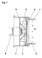
- the mixing device consists of a flame tube 1, which surrounds a combustion chamber 2, in which a fuel jet from a fuel nozzle 3 propagates. This is upstream of the combustion chamber 2, just behind a diaphragm 4 with a flow opening 5 for the combustion air, mounted on a so-called nozzle 6.
- the combustion air flow is conveyed into the housing 7 or through the distributor device 8 in the form of a disk-shaped perforated plate to the aperture 4.
- the combustion air flow is split at the distributor device 8 into a first inner and a second outer partial flow. Both coaxial partial flows are in the range the confluence of the fuel nozzle 3 again brought together close to the fuel jet and pass through the flow opening 5 therethrough.
- a cone 9 is fixed to the distribution device 8 with its base and opens in the region of the aperture 4 at a distance from the edge of the flow opening 5 and to the fuel nozzle 3.
- the cone 9 can according to FIG. 1 have a closed lateral surface or according to FIG. 2 a perforated surface 10 provided with openings.
Landscapes
- Engineering & Computer Science (AREA)
- Chemical & Material Sciences (AREA)
- Combustion & Propulsion (AREA)
- Mechanical Engineering (AREA)
- General Engineering & Computer Science (AREA)
- Gas Burners (AREA)
- Pressure-Spray And Ultrasonic-Wave- Spray Burners (AREA)
Applications Claiming Priority (1)
| Application Number | Priority Date | Filing Date | Title |
|---|---|---|---|
| DE200610049294 DE102006049294A1 (de) | 2006-10-19 | 2006-10-19 | Mischeinrichtung für einen Öl- oder Gasbrenner |
Publications (2)
| Publication Number | Publication Date |
|---|---|
| EP1916475A2 true EP1916475A2 (fr) | 2008-04-30 |
| EP1916475A3 EP1916475A3 (fr) | 2008-12-10 |
Family
ID=38654782
Family Applications (1)
| Application Number | Title | Priority Date | Filing Date |
|---|---|---|---|
| EP07019499A Withdrawn EP1916475A3 (fr) | 2006-10-19 | 2007-10-05 | Mélangeur de brûleur à gas ou à huile |
Country Status (2)
| Country | Link |
|---|---|
| EP (1) | EP1916475A3 (fr) |
| DE (1) | DE102006049294A1 (fr) |
Families Citing this family (1)
| Publication number | Priority date | Publication date | Assignee | Title |
|---|---|---|---|---|
| US10533740B2 (en) | 2015-07-09 | 2020-01-14 | Carrier Corporation | Inward fired ultra low NOX insulating burner flange |
Family Cites Families (11)
| Publication number | Priority date | Publication date | Assignee | Title |
|---|---|---|---|---|
| FR1495966A (fr) * | 1966-10-06 | 1967-09-22 | American Radiator & Standard | Brûleur à mazout |
| DE8200657U1 (de) * | 1982-01-14 | 1983-02-24 | Thermostar Heisler + Leins oHG Heizungs-und Klimatechnik, 7250 Leonberg | Oelvergasungsbrenner |
| AT401288B (de) * | 1991-10-14 | 1996-07-25 | Schwarz A & Co | Mischeinrichtung für ölbrenner |
| DE4208849A1 (de) * | 1992-03-19 | 1993-09-23 | Broetje August Gmbh & Co | Oelgeblaesebrenner |
| EP0646750A1 (fr) * | 1993-10-05 | 1995-04-05 | Abb Research Ltd. | Procédé de pulvérisation d'un combustible liquide dans une buse de pulvérisation |
| WO1995016882A1 (fr) * | 1993-12-18 | 1995-06-22 | Deutsche Forschungsanstalt für Luft- und Raumfahrt e.V. | Bruleur a flamme bleue optimisant la combustion |
| DE29508424U1 (de) * | 1995-05-20 | 1996-09-19 | Elco Energiesysteme AG, Vilters, St. Gallen | Brenner |
| DE29518919U1 (de) * | 1995-11-29 | 1996-01-25 | MEKU Metallverarbeitungs-GmbH, 78083 Dauchingen | Mischeinrichtung für einen Brenner |
| DE19604347A1 (de) * | 1996-02-07 | 1997-08-14 | Koerting Ag | Brenner für flüssigen oder gasförmigen Brennstoff, insbesondere für Öl |
| DE19741508A1 (de) * | 1997-08-16 | 1999-05-06 | Buderus Heiztechnik Gmbh | Mischeinrichtung |
| EP1243850B1 (fr) * | 2001-03-20 | 2007-10-03 | Riello S.p.a. | Brûleur à mazout |
-
2006
- 2006-10-19 DE DE200610049294 patent/DE102006049294A1/de not_active Ceased
-
2007
- 2007-10-05 EP EP07019499A patent/EP1916475A3/fr not_active Withdrawn
Also Published As
| Publication number | Publication date |
|---|---|
| EP1916475A3 (fr) | 2008-12-10 |
| DE102006049294A1 (de) | 2008-04-24 |
Similar Documents
| Publication | Publication Date | Title |
|---|---|---|
| EP0309838B1 (fr) | Brûleur à gaz | |
| DE69917655T2 (de) | System zur dämpfung akustischer schwingungen in einer brennkammer | |
| DE2653410C2 (de) | Flammrohrrückwand für Gasturbinen-Brennkammern | |
| CH702172A2 (de) | Brennkammer für eine Gasturbine ,mit verbesserter Kühlung. | |
| EP0018602A2 (fr) | Brûleur d'huile à gazéification | |
| EP2423597B1 (fr) | Brûleur à prémélange pour une turbine à gaz | |
| DE102016118633A1 (de) | Brennerkopf, Brennersystem und Verwendung des Brennersystems | |
| DE2712856A1 (de) | Oelbrenneranordnung fuer heizungsanlagen | |
| DE60224518T2 (de) | Vormischende turbinenverbrennungskammer | |
| EP4063733A1 (fr) | Dispositif permettant de réduire les conséquences d'un retour de flamme dans un brûleur à prémélange d'un appareil de chauffage | |
| EP1916475A2 (fr) | Mélangeur de brûleur à gas ou à huile | |
| DE2932378A1 (de) | Brennkammer fuer gasturbinentriebwerke | |
| DE2700786C3 (de) | Keramischer Gasbrenner für Winderhitzer | |
| EP1288574A1 (fr) | Agencement de chambre de combustion | |
| EP1489352B1 (fr) | Dispositif de mélange pour un brûleur au gaz ou au fioul | |
| EP3361153A2 (fr) | Dispositif formant brûleur à gaz pour un échangeur de chaleur | |
| DE102007053658B4 (de) | Brenner für flüssige Brennstoffe | |
| DE10254664B3 (de) | Brenner für flüssige Brennstoffe | |
| DE2819075A1 (de) | Atmosphaerischer zuend-gasbrenner | |
| DE10349836B3 (de) | Mischeinrichtung für einen Öl- oder Gasbrenner | |
| EP2407715B1 (fr) | Brûleur | |
| EP3102878B1 (fr) | Brûleur à gaz, table de cuisson et foyer | |
| DE2252358C3 (de) | Brenner für flüssigen Brennstoff | |
| DE10348272B3 (de) | Mischeinrichtung für einen Öl- oder Gasbrenner | |
| EP1731834A1 (fr) | Brûleur à combustible liquide |
Legal Events
| Date | Code | Title | Description |
|---|---|---|---|
| PUAI | Public reference made under article 153(3) epc to a published international application that has entered the european phase |
Free format text: ORIGINAL CODE: 0009012 |
|
| AK | Designated contracting states |
Kind code of ref document: A2 Designated state(s): AT BE BG CH CY CZ DE DK EE ES FI FR GB GR HU IE IS IT LI LT LU LV MC MT NL PL PT RO SE SI SK TR |
|
| AX | Request for extension of the european patent |
Extension state: AL BA HR MK RS |
|
| PUAL | Search report despatched |
Free format text: ORIGINAL CODE: 0009013 |
|
| AK | Designated contracting states |
Kind code of ref document: A3 Designated state(s): AT BE BG CH CY CZ DE DK EE ES FI FR GB GR HU IE IS IT LI LT LU LV MC MT NL PL PT RO SE SI SK TR |
|
| AX | Request for extension of the european patent |
Extension state: AL BA HR MK RS |
|
| AKX | Designation fees paid | ||
| STAA | Information on the status of an ep patent application or granted ep patent |
Free format text: STATUS: THE APPLICATION IS DEEMED TO BE WITHDRAWN |
|
| 18D | Application deemed to be withdrawn |
Effective date: 20090611 |
|
| REG | Reference to a national code |
Ref country code: DE Ref legal event code: 8566 |