EP1917451B1 - Mécanisme de rattrapage automatique d'usure destiné à régler le jeu entre la garniture de frein et le tambour de frein d'un systeme de freinage de véhicule - Google Patents
Mécanisme de rattrapage automatique d'usure destiné à régler le jeu entre la garniture de frein et le tambour de frein d'un systeme de freinage de véhicule Download PDFInfo
- Publication number
- EP1917451B1 EP1917451B1 EP06780532A EP06780532A EP1917451B1 EP 1917451 B1 EP1917451 B1 EP 1917451B1 EP 06780532 A EP06780532 A EP 06780532A EP 06780532 A EP06780532 A EP 06780532A EP 1917451 B1 EP1917451 B1 EP 1917451B1
- Authority
- EP
- European Patent Office
- Prior art keywords
- clutch
- brake
- way lock
- worm
- worm shaft
- Prior art date
- Legal status (The legal status is an assumption and is not a legal conclusion. Google has not performed a legal analysis and makes no representation as to the accuracy of the status listed.)
- Not-in-force
Links
- 230000006835 compression Effects 0.000 claims description 15
- 238000007906 compression Methods 0.000 claims description 15
- 238000007789 sealing Methods 0.000 claims description 8
- KZIDCBOXWFFCKL-UHFFFAOYSA-N 6-propan-2-ylcyclohexa-2,4-dien-1-one Chemical compound C1=CC(C(C)C)C(=O)C=C1 KZIDCBOXWFFCKL-UHFFFAOYSA-N 0.000 claims description 2
- 238000009434 installation Methods 0.000 description 3
- 238000004519 manufacturing process Methods 0.000 description 3
- 230000000717 retained effect Effects 0.000 description 3
- 230000007613 environmental effect Effects 0.000 description 2
- 239000002245 particle Substances 0.000 description 2
- 238000010276 construction Methods 0.000 description 1
- 230000000694 effects Effects 0.000 description 1
- 230000004048 modification Effects 0.000 description 1
- 238000012986 modification Methods 0.000 description 1
- 230000003068 static effect Effects 0.000 description 1
Images

Classifications
-
- F—MECHANICAL ENGINEERING; LIGHTING; HEATING; WEAPONS; BLASTING
- F16—ENGINEERING ELEMENTS AND UNITS; GENERAL MEASURES FOR PRODUCING AND MAINTAINING EFFECTIVE FUNCTIONING OF MACHINES OR INSTALLATIONS; THERMAL INSULATION IN GENERAL
- F16D—COUPLINGS FOR TRANSMITTING ROTATION; CLUTCHES; BRAKES
- F16D65/00—Parts or details
- F16D65/38—Slack adjusters
- F16D65/40—Slack adjusters mechanical
- F16D65/52—Slack adjusters mechanical self-acting in one direction for adjusting excessive play
- F16D65/56—Slack adjusters mechanical self-acting in one direction for adjusting excessive play with screw-thread and nut
- F16D65/561—Slack adjusters mechanical self-acting in one direction for adjusting excessive play with screw-thread and nut for mounting within the confines of a drum brake
- F16D65/562—Slack adjusters mechanical self-acting in one direction for adjusting excessive play with screw-thread and nut for mounting within the confines of a drum brake arranged between service brake actuator and braking member, and subjected to service brake force
-
- F—MECHANICAL ENGINEERING; LIGHTING; HEATING; WEAPONS; BLASTING
- F16—ENGINEERING ELEMENTS AND UNITS; GENERAL MEASURES FOR PRODUCING AND MAINTAINING EFFECTIVE FUNCTIONING OF MACHINES OR INSTALLATIONS; THERMAL INSULATION IN GENERAL
- F16D—COUPLINGS FOR TRANSMITTING ROTATION; CLUTCHES; BRAKES
- F16D65/00—Parts or details
- F16D65/38—Slack adjusters
- F16D65/40—Slack adjusters mechanical
- F16D65/52—Slack adjusters mechanical self-acting in one direction for adjusting excessive play
-
- F—MECHANICAL ENGINEERING; LIGHTING; HEATING; WEAPONS; BLASTING
- F16—ENGINEERING ELEMENTS AND UNITS; GENERAL MEASURES FOR PRODUCING AND MAINTAINING EFFECTIVE FUNCTIONING OF MACHINES OR INSTALLATIONS; THERMAL INSULATION IN GENERAL
- F16D—COUPLINGS FOR TRANSMITTING ROTATION; CLUTCHES; BRAKES
- F16D65/00—Parts or details
- F16D65/38—Slack adjusters
- F16D65/40—Slack adjusters mechanical
- F16D65/52—Slack adjusters mechanical self-acting in one direction for adjusting excessive play
- F16D65/60—Slack adjusters mechanical self-acting in one direction for adjusting excessive play for angular adjustment of two concentric parts of the brake control systems
-
- F—MECHANICAL ENGINEERING; LIGHTING; HEATING; WEAPONS; BLASTING
- F16—ENGINEERING ELEMENTS AND UNITS; GENERAL MEASURES FOR PRODUCING AND MAINTAINING EFFECTIVE FUNCTIONING OF MACHINES OR INSTALLATIONS; THERMAL INSULATION IN GENERAL
- F16D—COUPLINGS FOR TRANSMITTING ROTATION; CLUTCHES; BRAKES
- F16D2125/00—Components of actuators
- F16D2125/18—Mechanical mechanisms
- F16D2125/20—Mechanical mechanisms converting rotation to linear movement or vice versa
- F16D2125/22—Mechanical mechanisms converting rotation to linear movement or vice versa acting transversely to the axis of rotation
- F16D2125/28—Cams; Levers with cams
- F16D2125/30—Cams; Levers with cams acting on two or more cam followers, e.g. S-cams
Definitions
- This invention relates to an improvement on Automatic Brake Adjuster with flexible reference point wherein one-way lock mechanism and clutch mechanism are integrated in one part and located on the worm shaft with the provision of isolating the one way lock mechanism and regulator worm gear wheel from heavy clutch spring load by a thrust sleeve arrangement for independent function.
- One-way lock mechanism is meant for sensing the excess lining clearance and adjusting the slack between the brake lining and brake drum whereas the clutch mechanism is to ignore the excess stroke of brake actuator due to elasticity in the foundation brake parts of a vehicular braking system.
- Sush a brake adjuster is for instance known from WO-A-03/83322 .
- a "S" shaped cam shaft drum brakes In heavy commercial vehicle, such as trucks, trailers and buses generally a "S" shaped cam shaft drum brakes is widely used.
- the brake shoes with the brake lining rest on the "S” shaped cam shaft and are pressed against the brake drum during brake application.
- the splined portion of the "S" shaped camshaft protrudes out of the brake drum.
- a Brake Adjuster connects the said S cam shaft to a push rod of the brake actuator.
- the Brake Adjuster is fitted onto the splined portion of the 'S' cam shaft at one end and at the other is connected to the push rod of the brake actuator.
- the air pressure applied onto the brake actuator becomes the mechanical output which is transmitted as braking force through the push rod to the "S" shaped camshaft which expands the brake shoes and presses the lining against the brake drum so as to apply the brake.
- the Automatic Brake Adjuster serves the purpose as a lever that transmits the braking force from the brake actuator to the S-cam shaft and a mechanical device to sense the excess lining clearance and adjusts the slack between the brake lining and the brake drum to an optimized value.
- an Automatic Brake Adjuster is used as a lever to connect the push rod of the brake actuator and the splined camshaft of 'S' Cam brake.
- the 'S' cam brake consists of a brake drum, brake shoes and 'S'-camshaft. The brake shoe will be pressed against the brake drum during the application of brakes by the 'S' camshaft.
- the Automatic Brake Adjuster is used to transmit the braking force to the 'S' cam brake by the brake actuator that is operated by air pressure.
- the sensing of the slackness of the brake due to the lining wear by the Automatic Brake Adjuster can be either by stroke or by clearance between the lining and the drum.
- the adjustment entirely depends on the push rod stroke of the brake actuator, or in other words the angular movement of Automatic Brake Adjuster is varied by the clearance between the brake lining and the brake drum.
- the adjustment mechanism is able to sense various factors such as elasticity of brake drum and different structural parts in the brakes for varying the push rod stroke and differentiate the wear on the brake lining to optimize the lining clearance ignoring the influence of excess push rod stroke due to other factors.
- the clearance between brake lining and drum increases due to lining wear resulting in increased push rod stroke of the brake actuator to apply the brake. It is essential to maintain optimum clearance for effective braking and periodical manual adjustment to maintain the clearance. Therefore it is the main object of the invention to provide an automatic brake adjuster with an internal mechanism to sense the excess wear of the lining and automatically rotate, the worm shaft engaged with the worm wheel and in turn the "S camshaft" for maintaining optimum clearance, thereby maintaining the angular movement of the Automatic Brake Adjuster to the desired limit.
- an Automatic Brake Adjuster with a floating reference point with one way lock and clutch mechanism for adjusting the slack between brake lining and brake drum of a vehicular braking system comprising a body connectable to a brake actuator, a rotatable internally splined worm wheel in the other portion of the said body for receiving the S cam shaft, a clutch cum one way lock mechanism comprising a rotatable worm shaft secured perpendicular to worm wheel but meshing with the worm wheel, a one way lock/ clutch seat having serrations engaged with serrations of worm shaft which is guided by bearing retainer to form clutch mechanism and a regulator worm wheel engagable with one-way lock / clutch seat by means of a torsion spring mounted on hexagonal end of worm shaft such that clutch mechanism and one way lock mechanism are on the worm shaft, a bearing retainer along with a thrust bearing retains the one way lock/clutch seat through a thrust sleeve against a heavy compression spring,
- the body comprises a hole in the tail portion of the said body, the rotatable worm shaft is secured perpendicular to the axis of the worm wheel, the worm shaft is mounted at a hexagonal end of the worm shaft along with bearing retainer engagable to guide the worm shaft, the torsion spring is housed in the serrated bore of regulator worm wheel in one end and other end in one-way lock / clutch seat, the heavy compression spring along with a spring seat and a spring retainer are mounted on the other end of the worm shaft, a sealing ring secured in a groove of the worm shaft, said spring retainer screwed correspondingly onto the said body for presetting the spring load, the one way lock/ clutch seat forms a clutch by the serrations seating on serrations of worm shaft, the heavy compression spring exerts load onto the worm shaft so as to ensure the engagement of the clutch, one way lock is formed by torsion spring between regulator wheel and one-way lock / clutch seat by housing the torsion spring in the
- the common functional feature of an automatic brake adjuster is to sense the excess wear of lining and adjust excess clearance to maintain the optimum clearance for effective braking and eliminate periodical manual adjustment to maintain the clearance and automatic brake adjuster is to provide a highly reliable, which is a safety device to be capable of working under extremely bad environmental conditions and also under severe load and vibration conditions overcoming the limitation on space availability.
- a known Automatic Brake Adjuster In a known Automatic Brake Adjuster the angular movement thereof is sensed by the control arm anchored to a fixed part on the vehicle chassis for establishing the reference point. But it is also desirable to provide a flexible reference point for easy installation on various models of vehicles instead of having a fixed reference point mounting with reference to the Automatic Brake Adjuster body, to avoid the additional care required for the initial installation and also for easy installation for users during re-fitment and after servicing. To overcome the above problem the Control arm of the Automatic Brake Adjuster as per the invention is designed to have a floating reference point.
- An Automatic Brake Adjuster for adjusting the slack between brake lining and brake drum of a vehicular braking system as per the invention comprises mainly of following: -
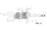
- the Automatic Brake Adjuster includes an Automatic Brake Adjuster body (1) provided with a hole (2) in the tail portion for connecting to the brake actuator.
- the other end of the body houses a rotatable worm wheel (3), which has internal splines for fixing the S camshaft.
- a rotatable Worm shaft (4) meshing with the worm wheel (3) is located in the body (1) perpendicular to the axis of the worm wheel (3).
- one end of the worm shaft (4) has a hexagon portion (4') protruding out of the body (1).
- a thrust sleeve (26), Regulator worm wheel (6), Torsion spring (28) and one-way lock / clutch seat (29) along with a thrust bearing (7) and a bearing retainer (5) which is screwed in to the body (1) and guides the worm shaft (4).
- the thrust sleeve (26) and the thrust bearing (7) are used to retain the one-way lock / clutch seat (29) for free rotation against the heavy compression spring (9) load.
- a one way lock mechanism is formed between regulator worm wheel (6) and One-way by the torsion spring (28) and positioned on the worm wheel (6) and worm shaft (4).
- the torsion spring which is housed in the serrated bore of regulator worm wheel (6) and One-way by the torsion spring (28) allows the regulator worm wheel (6) to rotate during the clockwise movement of Control arm (13) rotation and locks when rotated in opposite direction.
- a sealing ring (25) is provided in the groove of the worm shaft (4) to prevent the entry of foreign particles.
- On the other side of the worm shaft (4) is mounted the spring seat (10), heavy compression spring (9) and the spring retainer (11). The spring retainer (11) is screwed into the body (1) for setting the desired spring load.
- a clutch mechanism is formed by the serration (29') on one-way lock / clutch seat (29) and the serration (4") of the worm shaft (4).
- the engagement of this clutch is ensured by a heavy compression spring (9) that exerts load on to the worm shaft (4).
- the control arm assembly (12-15 Et 17) is located in the body on the same bore of the worm wheel (3) and independently operational.
- the rotatable control gear wheel (12) of the control arm assembly having gear teeth circumferentially is integral with Control arm (13), which has fixing portion (13').
- the cover plate (14) is located in between control gear wheel (12) and control arm (13) along with sealing rings (15) and (17) to avoid entry of foreign particles.
- control arm assembly (12-15 Et 17) is fixed on the body (1) with a Gasket (8) by means of screws (18) in the periphery holes of the cover plate (14).
- Control arm (13) is a rotatable attachment of the control arm assembly (12-15 Et 17).
- the fixing portion of control arm (13') is to be rigidly secured on the vehicle chassis and the purpose of this is to provide a reference point for the Automatic Brake Adjuster as explained below.
- the Control gear wheel (12) meshes with the pinion (16) and is located in the worm wheel bore of the body (1).
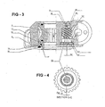
- the location of the pinion is shown in Fig. 3Et4 .
- Pinion (16) and control worm screw (19) are aligned together by a spindle (23) with, Guide (20) and retained by the screw (21).
- the gap (G) provided in between the stepped faces of pinion (16) and the control worm screw (19) bore face is to give free movement initially during the rotation of pinion (16) by control gear wheel (12) to achieve the desired slack between the brake shoe and the brake drum which is otherwise called as the clearance stroke of the Automatic Brake Adjuster.
- One-way lock mechanism formed between Regulator worm wheel (6) and one way lock /clutch seat (29) engageable on worm shaft (4) is to sense excess lining clearance due to wear and make adjustment automatically. All these parts are caged by means of retaining ring (30) on the thrust sleeve (26) to avoid the over ridding clutch serrations of one way lock /clutch seat (29) and worm shaft (4) when clutch is disengaged and for ease of assembly manufacturing and servicing the assembly.
- the Automatic Brake Adjuster with flexible reference point incorporates an integrated one-way lock and clutch mechanism over the worm shaft.
- the function of one way lock mechanism is to sense excess lining clearance due to wear and make adjustment automatically where as the function of clutch mechanism is to disengage worm shaft from regulator worm wheel during deflection stroke of brake actuator and both are caged together by means of a retaining ring.
- Provision of one way lock mechanism by a torsion spring ensures sensing of the increase in lining gap infinitesimally (very minutely) and caging of all these parts simplify the assembly manufacturing in addition to isolating the clutch seat from over ridding on worm shaft clutch serrations during deflection stroke of brake actuator which enables to increase the life of clutch serrations on worm shaft and one way lock / clutch seat.
- control worm screw and pinion The controlled radial clearance between control worm screw and pinion is ensured by the gap provided between stepped faces of pinion and control worm screw and assembled together in the spindle with torsion spring ensures desired slack or control distance for the Automatic Brake Adjuster for maintaining the clearance between the brake lining and the drum.
- the pinion, control worm screw are aligned together by spindle and is retained by a screw with guide to facilitate easy dismantling and re-assembling as shown in enclosed drawing (Fig-3). These parts are assembled in the body with the compression spring at the bottom.
- the pinion (16) When the Brake is applied with excess lining clearance to begin with during the initial brake application, the pinion (16) is rotated by the control arm assembly (12-15Et17), which is rigidly mounted on the vehicle chassis, due to the movement of the lever. During the initial period of this operation the pinion (16) rotates freely until the pre-set gap (G) between the stepped faces of control worm screw (19) and pinion (16) is closed. This free rotation of pinion (16) ensures predetermined clearance stroke of the Automatic Brake Adjuster. Simultaneously the worm wheel (3) is rotated in the counter clockwise direction along with Automatic Brake Adjuster body (1); in turn the S camshaft engaged with the worm wheel spline (3') is rotated to lift the brake lining towards the brake drum.
- control worm screw (19) is also rotated by the pinion (16), along with regulator worm wheel (6) in turn rotating the torsion spring (28).
- the regulator worm wheel (6) has to over ride over the torsion spring (28) and engaging to a new location when the there is excess clearance between brake drum and brake lining.
- the body (1) keeps rotating in clock-wise direction; the control gear wheel (12) continues to rotate the pinion (16) along with control worm screw (19) until the closed gap between control worm screw (19) and pinion (16) is restored against the torsion spring (24).
- This movement covers the clearance stroke of the Automatic Brake Adjuster, which was achieved during the initial period of brake application.
- the one way lock / clutch seat (29) and torsion spring (28) along with regulator worm wheel (6) are prevented from rotation due to the friction in clutch engaged condition during this period.
Landscapes
- Engineering & Computer Science (AREA)
- General Engineering & Computer Science (AREA)
- Mechanical Engineering (AREA)
- Braking Arrangements (AREA)
Claims (2)
- Dispositif de rattrapage automatique d'usure des freins avec un point de référence flottant doté d'un mécanisme d'embrayage et de blocage unidirectionnel destiné à régler le jeu entre la garniture de frein et le tambour de frein d'un système de freinage de véhicule, comprenant :- un corps (1) susceptible d'être relié à un actionneur de frein,- une roue à denture hélicoïdale intérieure (3) susceptible de tourner dans l'autre partie dudit corps destinée à recevoir un arbre à cames en S,- un embrayage doté d'un mécanisme de blocage unidirectionnel comprenant un arbre à vis sans fin rotatif (4) monté perpendiculairement à la roue à denture hélicoïdale (3), et se mettant en prise avec cette dernière, un support d'embrayage / dispositif de blocage unidirectionnel (29) comportant une denture (29') en prise avec la denture (4") de l'arbre à vis sans fin (4) qui est guidé par une couronne d'appui (5) pour former un mécanisme d'embrayage et une roue régulatrice à denture hélicoïdale (6) susceptible de se mettre en prise avec le support d'embrayage / dispositif de blocage unidirectionnel (29) à l'aide d'un ressort de torsion (28) monté sur une extrémité hexagonale (4') de l'arbre à vis sans fin (4) de telle sorte que le mécanisme d'embrayage et le mécanisme de blocage unidirectionnel sont placés sur l'arbre à vis sans fin (4),- une couronne d'appui (5) dotée d'un palier de butée (7) retient le support d'embrayage / dispositif de blocage unidirectionnel (29) par l'intermédiaire d'une douille de pression (26) sous l'action d'un ressort antagoniste (9), isolant ainsi la roue régulatrice à denture hélicoïdale (6) et du ressort de torsion (28) pour garantir un libre déplacement,dans lequel le mécanisme de blocage unidirectionnel et le mécanisme d'embrayage sont placés sur l'arbre à vis sans fin, et
dans lequel le mécanisme de blocage unidirectionnel et le mécanisme d'embrayage sont solidaires pour former une pièce unique sur le support d'embrayage / dispositif de blocage unidirectionnel (29),
caractérisé en ce que,
le ressort de torsion (28) est placé sur la douille de pression (26), et une bague de retenue (30) est prévue sur la douille de pression (26) et emprisonne le manchon de blocage unidirectionnel et la roue régulatrice à denture hélicoïdale (6) afin d'isoler les dents (29") du support d'embrayage pour les empêcher de s'accoupler avec les dents (4") d'engrenage de l'arbre à vis sans fin alors que l'embrayage est désaccouplé. - Dispositif de rattrapage automatique d'usure des freins selon la revendication 1, dans lequel- le corps (1) comprend un orifice (2) dans la partie arrière dudit corps,- l'arbre à vis sans fin rotatif (4) est fixé perpendiculairement à l'axe de la roue à denture hélicoïdale (3),- l'arbre à vis sans fin est monté au niveau d'une extrémité hexagonale (4') de l'arbre à vis sans fin (4), la couronne d'appui (5) étant susceptible de se mettre en prise pour guider l'arbre à vis sans fin (4),- le ressort de torsion (28) est logé dans l'alésage denté de la roue régulatrice à denture hélicoïdale (6) à une extrémité, l'autre extrémité étant placée dans le support d'embrayage / dispositif de blocage unidirectionnel (29),- le ressort antagoniste (9), doté d'un siège (10) de ressort et une coupelle d'appui (11) sont montés à l'autre extrémité de l'arbre à vis sans fin (4),- une bague d'étanchéité (25) est fixée dans une rainure de l'arbre à vis sans fin (4),- ladite coupelle d'appui (11) du ressort est en conséquence vissée sur ledit corps (1) afin de prérégler la charge du ressort,- le support d'embrayage / dispositif de blocage unidirectionnel (29) forme un embrayage par engrenage des dents (29') sur les dents (4") de l'arbre à vis sans fin,- le ressort antagoniste (9) exerce une pression sur l'arbre à vis sans fin (4) de sorte à mettre en prise l'embrayage,- le dispositif de blocage unidirectionnel est formé par le ressort de torsion (28) placé entre la roue régulatrice (6) et le support d'embrayage / dispositif de blocage unidirectionnel (29), le ressort de torsion (28) venant se loger dans les dents de l'alésage de la roue régulatrice (6) et le support d'embrayage / dispositif de blocage unidirectionnel (29) à l'autre extrémité,
et comprenant en outre :- un ensemble formant bras de commande comprenant :- un bras de commande tournant (13) comportant une partie de fixation (13'),- une roue dentée de commande (12) dotée de dents sur sa circonférence et située dans l'alésage de la roue à denture hélicoïdale (3) et solidaire du bras de commande (13),- une plaque formant couvercle (14) dotée de bagues d'étanchéité (15 et 17) est montée entre la roue dentée de commande (12) et le bras de commande (13),- dans lequel un joint (8) doté de vis (18) placées dans les trous ménagés à la périphérie de la plaque formant couvercle (14) est prévu pour garantir une fixation rigide sur le corps (1),- dans lequel la partie de fixation (13') est solidement montée sur le châssis du véhicule pour servir de point de référence, et- un ensemble formant pignon comprenant :- un pignon (16) destiné à se mettre en prise avec la roue dentée de commande (12),- doté de faces en gradins,- une vis de réglage sans fin (19) à épaulements adaptée pour se mettre en prise avec les faces en gradins du pignon (16),- dans lequel une tige (23), un guide (20) et une vis (21) permettent d'aligner le pignon (16) et la vis de réglage sans fin (19),- dans lequel l'espace (G) entre les faces en gradins du pignon (16) et la face alésée de la vis de réglage sans fin (19) prévoit un jeu dans le sens radial pour permettre- un libre déplacement initialement lors de la rotation du pignon (16) sous l'action de la roue dentée de commande (12), permettant ainsi le déplacement radial requis pour obtenir le jeu voulu entre le patin de frein et le tambour de frein, appelé course de rattrapage de jeu du dispositif automatique de rattrapage d'usure des freins.
Applications Claiming Priority (2)
| Application Number | Priority Date | Filing Date | Title |
|---|---|---|---|
| IN1176CH2005 | 2005-08-25 | ||
| PCT/IN2006/000248 WO2007023508A1 (fr) | 2005-08-25 | 2006-07-13 | Mécanisme de rattrapage automatique d’usure destiné à régler le jeu entre la garniture de frein et le tambour de frein d’un systeme de freinage de véhicule |
Publications (2)
| Publication Number | Publication Date |
|---|---|
| EP1917451A1 EP1917451A1 (fr) | 2008-05-07 |
| EP1917451B1 true EP1917451B1 (fr) | 2009-09-16 |
Family
ID=37238420
Family Applications (1)
| Application Number | Title | Priority Date | Filing Date |
|---|---|---|---|
| EP06780532A Not-in-force EP1917451B1 (fr) | 2005-08-25 | 2006-07-13 | Mécanisme de rattrapage automatique d'usure destiné à régler le jeu entre la garniture de frein et le tambour de frein d'un systeme de freinage de véhicule |
Country Status (10)
| Country | Link |
|---|---|
| US (1) | US8245820B2 (fr) |
| EP (1) | EP1917451B1 (fr) |
| KR (1) | KR101121125B1 (fr) |
| CN (1) | CN101248288B (fr) |
| AT (1) | ATE443217T1 (fr) |
| BR (1) | BRPI0615072A2 (fr) |
| DE (1) | DE602006009279D1 (fr) |
| ES (1) | ES2333048T3 (fr) |
| RU (1) | RU2406894C2 (fr) |
| WO (1) | WO2007023508A1 (fr) |
Cited By (1)
| Publication number | Priority date | Publication date | Assignee | Title |
|---|---|---|---|---|
| EP3093518A1 (fr) * | 2015-05-11 | 2016-11-16 | WABCO Europe BVBA | Unité de réglage pour un régleur automatique de timonerie |
Families Citing this family (18)
| Publication number | Priority date | Publication date | Assignee | Title |
|---|---|---|---|---|
| US8302744B2 (en) * | 2008-07-28 | 2012-11-06 | Bendix Spicer Foundation Brake Llc | Automatic slack adjuster anchor unit with a one-way clutch |
| BRMU8900388U2 (pt) | 2009-03-16 | 2010-11-30 | Lisecki Ind De Pecas Metalmecanicas Ltda | ajustador automático de folga de freio |
| WO2011016047A1 (fr) * | 2009-08-03 | 2011-02-10 | Madras Engineering Industries Private Limited | Ajusteur de freinage automatique destiné à ajuster le jeu entre la garniture de frein et le tambour de frein du système de freinage dun véhicule |
| KR101525146B1 (ko) * | 2012-05-31 | 2015-06-03 | 상신브레이크주식회사 | 간극을 일정하게 유지하는 디스크 브레이크 |
| CN103573878A (zh) * | 2013-11-05 | 2014-02-12 | 安徽工贸职业技术学院 | 一种机动车制动调节体 |
| US10197123B2 (en) | 2016-08-04 | 2019-02-05 | Tse Brakes, Inc. | Vehicle braking systems with automatic slack adjusters |
| US10378604B2 (en) | 2017-12-07 | 2019-08-13 | Bendix Spicer Foundation Brake Llc | Slack adjuster for a drum brake of a vehicle air braking system |
| US10704630B2 (en) | 2018-05-14 | 2020-07-07 | Bendix Spicer Foundation Brake Llc | Automatic slack adjuster with adjusting clutch in control train |
| CN109372917B (zh) * | 2018-12-18 | 2024-05-28 | Bpw(梅州)车轴有限公司 | 一种汽车制动器的自动间隙调整臂及其旋转角度控制装置 |
| CN109747602A (zh) * | 2019-01-19 | 2019-05-14 | 王刚 | 节能型车辆制动装置 |
| CN109882547A (zh) * | 2019-02-28 | 2019-06-14 | 江苏泰隆减速机股份有限公司 | 一种蜗杆制动蜗轮副的减速机 |
| US11209062B2 (en) | 2019-05-15 | 2021-12-28 | Bendix Commercial Vehicle Systems Llc | Automatic slack adjuster |
| CN113623344B (zh) * | 2020-05-09 | 2023-02-21 | 威伯科印度有限公司 | 用于车辆的自动松弛调节器、制动系统和轮副 |
| KR102435700B1 (ko) * | 2020-11-18 | 2022-08-24 | 김종우 | 캠핑 트레일러용 관성 브레이크 라이닝 조절기 |
| CN112572277B (zh) * | 2020-12-14 | 2022-07-26 | 中国兵器工业集团江山重工研究院有限公司 | 一种持续锁紧力装置 |
| CN114046323B (zh) * | 2021-09-30 | 2023-07-28 | 浙江万安科技股份有限公司 | 一种制动间隙自动调整臂 |
| CN114087303A (zh) * | 2021-10-27 | 2022-02-25 | 瑞立集团瑞安汽车零部件有限公司 | 一种高强度密封性能好的自动间隙调整臂 |
| CN114483831B (zh) * | 2022-03-10 | 2025-05-16 | 大川电机科技(江苏)有限公司 | 一种电动车离合器 |
Family Cites Families (10)
| Publication number | Priority date | Publication date | Assignee | Title |
|---|---|---|---|---|
| GB1308442A (en) * | 1969-06-25 | 1973-02-21 | Girling Ltd | Automatic adjuster for shoe drum brakes |
| SE420014B (sv) | 1979-12-13 | 1981-09-07 | Sab Automotive Ab | Bromshevarm for en trumbroms |
| SE438718B (sv) * | 1980-11-26 | 1985-04-29 | Svensson Sten Eric | Regulator for automatisk efterstellning av fordonsbromsar |
| SE451751B (sv) | 1982-09-30 | 1987-10-26 | Svensson Sten Eric | Regulator for automatisk efterstellning av fordonsbromsar |
| US5036958A (en) * | 1989-08-28 | 1991-08-06 | Krestbuch Engineering, Inc. | Automatic slack adjuster for vehicle brakes |
| SE470526B (sv) * | 1992-11-18 | 1994-07-04 | Haldex Ab | Bromshävarm för en s-kambroms hos ett landsvägsfordon |
| RU2078001C1 (ru) | 1994-09-05 | 1997-04-27 | Андрей Андреевич Боталенко | Регулятор тормоза транспортного средства |
| WO2003083322A1 (fr) | 2002-04-01 | 2003-10-09 | Madras Engineering Industries Limited | Dispositif de reglage automatique des freins pour le rattrapage de jeu entre la garniture de frein et le tambour de frein dans un systeme de freinage de vehicule automobile |
| CN100455840C (zh) * | 2004-04-07 | 2009-01-28 | 马德拉斯机器制造私人有限公司 | 用于调整车辆制动系统的制动衬片和制动鼓之间间隙的制动间隙自动调整器 |
| US7198138B2 (en) * | 2004-06-14 | 2007-04-03 | Ang Automotive India Private Limited | Automatic slack adjuster assembly for vehicle braking system |
-
2006
- 2006-07-13 RU RU2008105749/11A patent/RU2406894C2/ru not_active IP Right Cessation
- 2006-07-13 KR KR1020087005291A patent/KR101121125B1/ko not_active Expired - Fee Related
- 2006-07-13 US US11/990,872 patent/US8245820B2/en not_active Expired - Fee Related
- 2006-07-13 BR BRPI0615072-1A patent/BRPI0615072A2/pt not_active IP Right Cessation
- 2006-07-13 AT AT06780532T patent/ATE443217T1/de not_active IP Right Cessation
- 2006-07-13 EP EP06780532A patent/EP1917451B1/fr not_active Not-in-force
- 2006-07-13 DE DE602006009279T patent/DE602006009279D1/de active Active
- 2006-07-13 WO PCT/IN2006/000248 patent/WO2007023508A1/fr not_active Ceased
- 2006-07-13 CN CN200680030843XA patent/CN101248288B/zh not_active Expired - Fee Related
- 2006-07-13 ES ES06780532T patent/ES2333048T3/es active Active
Cited By (1)
| Publication number | Priority date | Publication date | Assignee | Title |
|---|---|---|---|---|
| EP3093518A1 (fr) * | 2015-05-11 | 2016-11-16 | WABCO Europe BVBA | Unité de réglage pour un régleur automatique de timonerie |
Also Published As
| Publication number | Publication date |
|---|---|
| WO2007023508A1 (fr) | 2007-03-01 |
| CN101248288B (zh) | 2010-12-29 |
| ES2333048T3 (es) | 2010-02-16 |
| KR20080037700A (ko) | 2008-04-30 |
| BRPI0615072A2 (pt) | 2013-01-01 |
| EP1917451A1 (fr) | 2008-05-07 |
| US8245820B2 (en) | 2012-08-21 |
| DE602006009279D1 (de) | 2009-10-29 |
| RU2008105749A (ru) | 2009-09-27 |
| HK1119454A1 (en) | 2009-03-06 |
| CN101248288A (zh) | 2008-08-20 |
| KR101121125B1 (ko) | 2012-03-19 |
| US20100288590A1 (en) | 2010-11-18 |
| ATE443217T1 (de) | 2009-10-15 |
| RU2406894C2 (ru) | 2010-12-20 |
Similar Documents
| Publication | Publication Date | Title |
|---|---|---|
| EP1917451B1 (fr) | Mécanisme de rattrapage automatique d'usure destiné à régler le jeu entre la garniture de frein et le tambour de frein d'un systeme de freinage de véhicule | |
| EP1805431B1 (fr) | Régleur de semelle de frein automatique permettant de régler le jeu entre les garnitures de frein et le tambour de frein du système de freinage d'un véhicule | |
| US5327999A (en) | Brake lever for an S-cam automotive drum brake | |
| WO2003083322A1 (fr) | Dispositif de reglage automatique des freins pour le rattrapage de jeu entre la garniture de frein et le tambour de frein dans un systeme de freinage de vehicule automobile | |
| US4830149A (en) | Actuator with automatic adjustment and with reset shaft for use in brakes, especially of heavy duty vehicles | |
| JPH0247610B2 (fr) | ||
| US7198138B2 (en) | Automatic slack adjuster assembly for vehicle braking system | |
| CN113825924A (zh) | 自动间隙调节器 | |
| EP2480798B1 (fr) | Ajusteur de freinage automatique destiné à ajuster le jeu entre la garniture de frein et le tambour de frein du système de freinage d'un véhicule | |
| US8820490B2 (en) | Manual adjuster for automatic slack adjuster | |
| WO2019112828A1 (fr) | Dispositif de réglage de jeu pour frein à tambour de système de freinage pneumatique de véhicule | |
| CA3041903C (fr) | Dispositif d'ajustement de jeu automatique a ajustement d'embrayage dans un train de commande | |
| EP2639474A2 (fr) | Ensemble de réglage dans une enveloppe de rattrapeur d'usure automatique | |
| US11293506B2 (en) | Automatic slack adjuster | |
| GB2168439A (en) | A disc brake actuator with slack adjustment | |
| KR100839951B1 (ko) | 차량 브레이킹 시스템의 브레이크 라이닝과 브레이크 드럼 사이의 슬랙을 조정하기 위한 자동 브레이크 조정기 | |
| HK1119454B (en) | An automatic brake adjuster for adjusting the slack between the brake lining and brake drum of a vehicular braking system | |
| HK1105677B (en) | An automatic brake adjuster for adjusting the slack between the brake lining and brake drum of a vehicular braking system | |
| HK40000163A (en) | An automatic slack adjuster | |
| GB1596324A (en) | Pressure medium operable disc brake |
Legal Events
| Date | Code | Title | Description |
|---|---|---|---|
| PUAI | Public reference made under article 153(3) epc to a published international application that has entered the european phase |
Free format text: ORIGINAL CODE: 0009012 |
|
| 17P | Request for examination filed |
Effective date: 20080221 |
|
| AK | Designated contracting states |
Kind code of ref document: A1 Designated state(s): AT BE BG CH CY CZ DE DK EE ES FI FR GB GR HU IE IS IT LI LT LU LV MC NL PL PT RO SE SI SK TR |
|
| 17Q | First examination report despatched |
Effective date: 20080904 |
|
| GRAP | Despatch of communication of intention to grant a patent |
Free format text: ORIGINAL CODE: EPIDOSNIGR1 |
|
| DAX | Request for extension of the european patent (deleted) | ||
| GRAS | Grant fee paid |
Free format text: ORIGINAL CODE: EPIDOSNIGR3 |
|
| GRAA | (expected) grant |
Free format text: ORIGINAL CODE: 0009210 |
|
| AK | Designated contracting states |
Kind code of ref document: B1 Designated state(s): AT BE BG CH CY CZ DE DK EE ES FI FR GB GR HU IE IS IT LI LT LU LV MC NL PL PT RO SE SI SK TR |
|
| REG | Reference to a national code |
Ref country code: GB Ref legal event code: FG4D |
|
| REG | Reference to a national code |
Ref country code: CH Ref legal event code: EP |
|
| REG | Reference to a national code |
Ref country code: IE Ref legal event code: FG4D |
|
| REF | Corresponds to: |
Ref document number: 602006009279 Country of ref document: DE Date of ref document: 20091029 Kind code of ref document: P |
|
| REG | Reference to a national code |
Ref country code: SE Ref legal event code: TRGR |
|
| PG25 | Lapsed in a contracting state [announced via postgrant information from national office to epo] |
Ref country code: LT Free format text: LAPSE BECAUSE OF FAILURE TO SUBMIT A TRANSLATION OF THE DESCRIPTION OR TO PAY THE FEE WITHIN THE PRESCRIBED TIME-LIMIT Effective date: 20090916 Ref country code: FI Free format text: LAPSE BECAUSE OF FAILURE TO SUBMIT A TRANSLATION OF THE DESCRIPTION OR TO PAY THE FEE WITHIN THE PRESCRIBED TIME-LIMIT Effective date: 20090916 |
|
| REG | Reference to a national code |
Ref country code: ES Ref legal event code: FG2A Ref document number: 2333048 Country of ref document: ES Kind code of ref document: T3 |
|
| LTIE | Lt: invalidation of european patent or patent extension |
Effective date: 20090916 |
|
| PG25 | Lapsed in a contracting state [announced via postgrant information from national office to epo] |
Ref country code: PL Free format text: LAPSE BECAUSE OF FAILURE TO SUBMIT A TRANSLATION OF THE DESCRIPTION OR TO PAY THE FEE WITHIN THE PRESCRIBED TIME-LIMIT Effective date: 20090916 Ref country code: NL Free format text: LAPSE BECAUSE OF FAILURE TO SUBMIT A TRANSLATION OF THE DESCRIPTION OR TO PAY THE FEE WITHIN THE PRESCRIBED TIME-LIMIT Effective date: 20090916 Ref country code: LV Free format text: LAPSE BECAUSE OF FAILURE TO SUBMIT A TRANSLATION OF THE DESCRIPTION OR TO PAY THE FEE WITHIN THE PRESCRIBED TIME-LIMIT Effective date: 20090916 Ref country code: SI Free format text: LAPSE BECAUSE OF FAILURE TO SUBMIT A TRANSLATION OF THE DESCRIPTION OR TO PAY THE FEE WITHIN THE PRESCRIBED TIME-LIMIT Effective date: 20090916 |
|
| NLV1 | Nl: lapsed or annulled due to failure to fulfill the requirements of art. 29p and 29m of the patents act | ||
| PG25 | Lapsed in a contracting state [announced via postgrant information from national office to epo] |
Ref country code: CY Free format text: LAPSE BECAUSE OF FAILURE TO SUBMIT A TRANSLATION OF THE DESCRIPTION OR TO PAY THE FEE WITHIN THE PRESCRIBED TIME-LIMIT Effective date: 20090916 |
|
| PG25 | Lapsed in a contracting state [announced via postgrant information from national office to epo] |
Ref country code: EE Free format text: LAPSE BECAUSE OF FAILURE TO SUBMIT A TRANSLATION OF THE DESCRIPTION OR TO PAY THE FEE WITHIN THE PRESCRIBED TIME-LIMIT Effective date: 20090916 Ref country code: IS Free format text: LAPSE BECAUSE OF FAILURE TO SUBMIT A TRANSLATION OF THE DESCRIPTION OR TO PAY THE FEE WITHIN THE PRESCRIBED TIME-LIMIT Effective date: 20100116 Ref country code: RO Free format text: LAPSE BECAUSE OF FAILURE TO SUBMIT A TRANSLATION OF THE DESCRIPTION OR TO PAY THE FEE WITHIN THE PRESCRIBED TIME-LIMIT Effective date: 20090916 Ref country code: CZ Free format text: LAPSE BECAUSE OF FAILURE TO SUBMIT A TRANSLATION OF THE DESCRIPTION OR TO PAY THE FEE WITHIN THE PRESCRIBED TIME-LIMIT Effective date: 20090916 Ref country code: PT Free format text: LAPSE BECAUSE OF FAILURE TO SUBMIT A TRANSLATION OF THE DESCRIPTION OR TO PAY THE FEE WITHIN THE PRESCRIBED TIME-LIMIT Effective date: 20100118 |
|
| PG25 | Lapsed in a contracting state [announced via postgrant information from national office to epo] |
Ref country code: SK Free format text: LAPSE BECAUSE OF FAILURE TO SUBMIT A TRANSLATION OF THE DESCRIPTION OR TO PAY THE FEE WITHIN THE PRESCRIBED TIME-LIMIT Effective date: 20090916 |
|
| PG25 | Lapsed in a contracting state [announced via postgrant information from national office to epo] |
Ref country code: BE Free format text: LAPSE BECAUSE OF FAILURE TO SUBMIT A TRANSLATION OF THE DESCRIPTION OR TO PAY THE FEE WITHIN THE PRESCRIBED TIME-LIMIT Effective date: 20090916 Ref country code: AT Free format text: LAPSE BECAUSE OF FAILURE TO SUBMIT A TRANSLATION OF THE DESCRIPTION OR TO PAY THE FEE WITHIN THE PRESCRIBED TIME-LIMIT Effective date: 20090916 |
|
| PLBE | No opposition filed within time limit |
Free format text: ORIGINAL CODE: 0009261 |
|
| STAA | Information on the status of an ep patent application or granted ep patent |
Free format text: STATUS: NO OPPOSITION FILED WITHIN TIME LIMIT |
|
| PG25 | Lapsed in a contracting state [announced via postgrant information from national office to epo] |
Ref country code: DK Free format text: LAPSE BECAUSE OF FAILURE TO SUBMIT A TRANSLATION OF THE DESCRIPTION OR TO PAY THE FEE WITHIN THE PRESCRIBED TIME-LIMIT Effective date: 20090916 |
|
| 26N | No opposition filed |
Effective date: 20100617 |
|
| PG25 | Lapsed in a contracting state [announced via postgrant information from national office to epo] |
Ref country code: GR Free format text: LAPSE BECAUSE OF FAILURE TO SUBMIT A TRANSLATION OF THE DESCRIPTION OR TO PAY THE FEE WITHIN THE PRESCRIBED TIME-LIMIT Effective date: 20091217 |
|
| PG25 | Lapsed in a contracting state [announced via postgrant information from national office to epo] |
Ref country code: MC Free format text: LAPSE BECAUSE OF NON-PAYMENT OF DUE FEES Effective date: 20100731 |
|
| REG | Reference to a national code |
Ref country code: CH Ref legal event code: PL |
|
| PG25 | Lapsed in a contracting state [announced via postgrant information from national office to epo] |
Ref country code: LI Free format text: LAPSE BECAUSE OF NON-PAYMENT OF DUE FEES Effective date: 20100731 Ref country code: CH Free format text: LAPSE BECAUSE OF NON-PAYMENT OF DUE FEES Effective date: 20100731 |
|
| PG25 | Lapsed in a contracting state [announced via postgrant information from national office to epo] |
Ref country code: IE Free format text: LAPSE BECAUSE OF NON-PAYMENT OF DUE FEES Effective date: 20100713 |
|
| PG25 | Lapsed in a contracting state [announced via postgrant information from national office to epo] |
Ref country code: LU Free format text: LAPSE BECAUSE OF NON-PAYMENT OF DUE FEES Effective date: 20100713 Ref country code: BG Free format text: LAPSE BECAUSE OF FAILURE TO SUBMIT A TRANSLATION OF THE DESCRIPTION OR TO PAY THE FEE WITHIN THE PRESCRIBED TIME-LIMIT Effective date: 20090916 Ref country code: HU Free format text: LAPSE BECAUSE OF FAILURE TO SUBMIT A TRANSLATION OF THE DESCRIPTION OR TO PAY THE FEE WITHIN THE PRESCRIBED TIME-LIMIT Effective date: 20100317 |
|
| PG25 | Lapsed in a contracting state [announced via postgrant information from national office to epo] |
Ref country code: TR Free format text: LAPSE BECAUSE OF FAILURE TO SUBMIT A TRANSLATION OF THE DESCRIPTION OR TO PAY THE FEE WITHIN THE PRESCRIBED TIME-LIMIT Effective date: 20090916 |
|
| REG | Reference to a national code |
Ref country code: FR Ref legal event code: PLFP Year of fee payment: 11 |
|
| REG | Reference to a national code |
Ref country code: FR Ref legal event code: PLFP Year of fee payment: 12 |
|
| REG | Reference to a national code |
Ref country code: FR Ref legal event code: PLFP Year of fee payment: 13 |
|
| PGFP | Annual fee paid to national office [announced via postgrant information from national office to epo] |
Ref country code: IT Payment date: 20190730 Year of fee payment: 14 Ref country code: SE Payment date: 20190719 Year of fee payment: 14 Ref country code: ES Payment date: 20190822 Year of fee payment: 14 Ref country code: FR Payment date: 20190719 Year of fee payment: 14 Ref country code: DE Payment date: 20190719 Year of fee payment: 14 |
|
| PGFP | Annual fee paid to national office [announced via postgrant information from national office to epo] |
Ref country code: GB Payment date: 20190719 Year of fee payment: 14 |
|
| REG | Reference to a national code |
Ref country code: DE Ref legal event code: R119 Ref document number: 602006009279 Country of ref document: DE |
|
| REG | Reference to a national code |
Ref country code: SE Ref legal event code: EUG |
|
| GBPC | Gb: european patent ceased through non-payment of renewal fee |
Effective date: 20200713 |
|
| PG25 | Lapsed in a contracting state [announced via postgrant information from national office to epo] |
Ref country code: GB Free format text: LAPSE BECAUSE OF NON-PAYMENT OF DUE FEES Effective date: 20200713 Ref country code: FR Free format text: LAPSE BECAUSE OF NON-PAYMENT OF DUE FEES Effective date: 20200731 |
|
| PG25 | Lapsed in a contracting state [announced via postgrant information from national office to epo] |
Ref country code: SE Free format text: LAPSE BECAUSE OF NON-PAYMENT OF DUE FEES Effective date: 20200714 Ref country code: DE Free format text: LAPSE BECAUSE OF NON-PAYMENT OF DUE FEES Effective date: 20210202 |
|
| PG25 | Lapsed in a contracting state [announced via postgrant information from national office to epo] |
Ref country code: IT Free format text: LAPSE BECAUSE OF NON-PAYMENT OF DUE FEES Effective date: 20200713 |
|
| REG | Reference to a national code |
Ref country code: ES Ref legal event code: FD2A Effective date: 20211230 |
|
| PG25 | Lapsed in a contracting state [announced via postgrant information from national office to epo] |
Ref country code: ES Free format text: LAPSE BECAUSE OF NON-PAYMENT OF DUE FEES Effective date: 20200714 |