EP1918613A2 - Schmiermittelstandregelung bei Antriebskopfanordnungen von Fahrzeugen - Google Patents
Schmiermittelstandregelung bei Antriebskopfanordnungen von Fahrzeugen Download PDFInfo
- Publication number
- EP1918613A2 EP1918613A2 EP07254256A EP07254256A EP1918613A2 EP 1918613 A2 EP1918613 A2 EP 1918613A2 EP 07254256 A EP07254256 A EP 07254256A EP 07254256 A EP07254256 A EP 07254256A EP 1918613 A2 EP1918613 A2 EP 1918613A2
- Authority
- EP
- European Patent Office
- Prior art keywords
- lubricant
- crown wheel
- shield
- driving head
- valve
- Prior art date
- Legal status (The legal status is an assumption and is not a legal conclusion. Google has not performed a legal analysis and makes no representation as to the accuracy of the status listed.)
- Granted
Links
Images



Classifications
-
- F—MECHANICAL ENGINEERING; LIGHTING; HEATING; WEAPONS; BLASTING
- F16—ENGINEERING ELEMENTS AND UNITS; GENERAL MEASURES FOR PRODUCING AND MAINTAINING EFFECTIVE FUNCTIONING OF MACHINES OR INSTALLATIONS; THERMAL INSULATION IN GENERAL
- F16H—GEARING
- F16H57/00—General details of gearing
- F16H57/04—Features relating to lubrication or cooling or heating
- F16H57/048—Type of gearings to be lubricated, cooled or heated
- F16H57/0482—Gearings with gears having orbital motion
- F16H57/0483—Axle or inter-axle differentials
-
- F—MECHANICAL ENGINEERING; LIGHTING; HEATING; WEAPONS; BLASTING
- F16—ENGINEERING ELEMENTS AND UNITS; GENERAL MEASURES FOR PRODUCING AND MAINTAINING EFFECTIVE FUNCTIONING OF MACHINES OR INSTALLATIONS; THERMAL INSULATION IN GENERAL
- F16H—GEARING
- F16H57/00—General details of gearing
- F16H57/04—Features relating to lubrication or cooling or heating
- F16H57/0409—Features relating to lubrication or cooling or heating characterised by increasing efficiency, e.g. by reducing splash losses
-
- F—MECHANICAL ENGINEERING; LIGHTING; HEATING; WEAPONS; BLASTING
- F16—ENGINEERING ELEMENTS AND UNITS; GENERAL MEASURES FOR PRODUCING AND MAINTAINING EFFECTIVE FUNCTIONING OF MACHINES OR INSTALLATIONS; THERMAL INSULATION IN GENERAL
- F16H—GEARING
- F16H57/00—General details of gearing
- F16H57/04—Features relating to lubrication or cooling or heating
- F16H57/042—Guidance of lubricant
- F16H57/0421—Guidance of lubricant on or within the casing, e.g. shields or baffles for collecting lubricant, tubes, pipes, grooves, channels or the like
- F16H57/0423—Lubricant guiding means mounted or supported on the casing, e.g. shields or baffles for collecting lubricant, tubes or pipes
-
- F—MECHANICAL ENGINEERING; LIGHTING; HEATING; WEAPONS; BLASTING
- F16—ENGINEERING ELEMENTS AND UNITS; GENERAL MEASURES FOR PRODUCING AND MAINTAINING EFFECTIVE FUNCTIONING OF MACHINES OR INSTALLATIONS; THERMAL INSULATION IN GENERAL
- F16H—GEARING
- F16H57/00—General details of gearing
- F16H57/04—Features relating to lubrication or cooling or heating
- F16H57/0447—Control of lubricant levels, e.g. lubricant level control dependent on temperature
-
- F—MECHANICAL ENGINEERING; LIGHTING; HEATING; WEAPONS; BLASTING
- F16—ENGINEERING ELEMENTS AND UNITS; GENERAL MEASURES FOR PRODUCING AND MAINTAINING EFFECTIVE FUNCTIONING OF MACHINES OR INSTALLATIONS; THERMAL INSULATION IN GENERAL
- F16H—GEARING
- F16H57/00—General details of gearing
- F16H57/04—Features relating to lubrication or cooling or heating
- F16H57/0457—Splash lubrication
Definitions
- the present invention relates to lubricant level control in vehicle driving head assemblies, more particularly, but not exclusively, to an apparatus and method for reducing lubricant associated power losses in a driving head assembly of an automotive vehicle.
- a conventional rear axle for an automotive vehicle incorporates a driving head assembly for transferring power from the vehicle drive shaft to the rear wheels, whilst allowing the wheels to rotate at different speeds as the vehicle is turning.
- a driving head assembly for transferring power from the vehicle drive shaft to the rear wheels, whilst allowing the wheels to rotate at different speeds as the vehicle is turning.
- Such an assembly is occasionally referred to in general terms as a differential.
- a typical driving head assembly consists of a housing, often referred to as a carrier, in which there is mounted a rotatable ring gear, more commonly referred to as a crown wheel.
- the crown wheel is arranged in mesh with a pinion at the end of the vehicle drive shaft. Rotation of the drive shaft causes rotation of the crown wheel within the carrier, via the pinion.
- the crown wheel is fixedly mounted about a casing for a set of differential gears, which include side gears operatively coupled to a pair of rear axle shafts extending from the carrier, generally perpendicular to the drive shaft.
- the differential side gears are configured to enable the rear axle shafts to rotate at different speeds when the vehicle is cornering.
- a volume of lubricant is usually provided in the carrier, for cooling purposes and reducing wear.
- lubricant is picked up by the rotating crown wheel and thrown forward in the direction of the pinion.
- the rotation of the crown wheel and the casing through the lubricant can lead to losses in power transmission, thereby increasing the overall fuel consumption of the vehicle.
- a device for reducing lubricant related losses in a driving head assembly is described and illustrated in US 6,299,561 .
- Walls project from a lower wall of the carrier, one arranged on either side of the crown wheel, to form what is referred to as a "dam area" around the lower end of the crown wheel.
- adam area around the lower end of the crown wheel.
- lubricant in the dam area is splashed over the walls, thereby reducing the level of lubricant in contact with the crown wheel and casing.
- the reduction in lubricant level leads to a reduction in shear or churning losses caused by the movement of the crown wheel and casing through the lubricant.
- Gate valves are provided in the walls to control the return of lubricant to the dam area between the walls. The flow of lubricant through the valves is controlled as a function of vehicle speed, whereby to minimise the level of lubricant in contact with the crown wheel at high rotational speeds.
- a lubricant level control housing or shield configured to be fitted around at least a portion of crown wheel in a vehicle driving head assembly, the shield defining a mouth into which at least an external portion of the crown wheel is intended to extend, to provide a cover for a portion of the crown wheel.
- the use of a separate housing for mounting in a driving head assembly, as opposed to an integrally formed dam of the kind described in the prior art, is advantageous in that the housing can be fabricated independently of the carrier body, for example from sheet metal, and readily installed about the crown wheel, without significantly effecting the assembly process of the driving head assembly.
- the housing also has application as a retro-fit item.
- the housing has an internal profile configured to match the general external profile of the crown wheel so as to define a working clearance between the internal surface of the housing and the crown wheel, in use.
- This form of close-fitting housing provides a greater, more responsive degree of lubricant level control than the simple walled construction of the prior art.
- a valve may be provided for regulating the flow of liquid into the shield.
- a temperature sensor may be provided for monitoring the temperature of lubricant adjacent the shield.
- the flow control valve may be controlled in response to readings from the temperature sensor, e.g. to open the valve when the temperature in the housing exceeds a threshold value.
- a driving head assembly for an automotive vehicle, the driving head assembly including a carrier body having first and second body parts and defining a major axis of rotation for an axle of the vehicle, a crown wheel and a differential casing mounted within the carrier body, wherein the crown wheel and differential casing are rotatably supported on said first body part for rotation about said major axis of rotation and wherein said crown wheel and differential casing extend from the first body part into said second body part, the driving head assembly further including a lubricant control chamber around the crown wheel, wherein the lubricant control chamber is in the form of a separate housing having a mouth into which at least an external portion of the crown wheel is intended to extend, to provide a cover for a portion of the crown wheel.
- the housing preferably has an internal profile configured to match the general external profile of the crown wheel so as to define a working clearance between the internal surface of the housing and the crown wheel, in use.
- the housing is preferably configured to fit over at least a portion of the differential casing, and may have an internal profile configured to match the general external profile of the differential casing, with a working clearance provided therebetween.
- the carrier body preferably defines a horizontal datum extending through the major axis of rotation of the rear axle, and wherein the first part of the carrier body has an end face which defines a generally vertical plane relative to said horizontal datum, a circumferential portion of the crown wheel extending from the first portion in a plane which is perpendicular to said vertical plane, wherein the housing is secured on to said end face of the first part of the carrier body.
- the carrier body defines a horizontal datum extending through the major axis of rotation of the rear axle, and wherein the first part of the carrier body has an end face which defines a generally vertical plane relative to said horizontal datum, a circumferential portion of the crown wheel extending from the first portion in a plane which is perpendicular to said vertical plane, wherein the housing is configured to cover at least the lower half of the section of crown wheel extending from the first part of the carrier body, at least up to the level of the horizontal datum.
- the housing may include an array of apertures provided above the level of said horizontal datum.
- the driving head assembly includes a control valve, preferably located in a lower region of the housing, for regulating the flow of lubricant into the control chamber.
- a lubricant health sensor may also be provided, preferably in a lower region of the housing, for monitoring the temperature and/or viscous quality of the lubricant in the control chamber.
- a heater may be provided for heating lubricant adjacent the housing.
- Baffles or other flow preventing devices are preferably provided in the carrier body to prevent the flow of lubricant into the control chamber via the differential casing.
- a method of controlling the level of lubricant around a crown wheel wherein a valve is opened to permit a flow of lubricant into a chamber formed around the crown wheel, if the temperature of lubricant adjacent the crown wheel exceeds a threshold.
- a method of controlling the level of lubricant-related losses in a driving head assembly for an automotive vehicle including a carrier body, a crown wheel and a differential casing rotatably mounted within the carrier body, a lubricant chamber around at least a portion of the external diameter of the crown wheel, a valve in fluid communication with said chamber, and a control unit in operative communication with said valve, the method including the step of regulating the flow of lubricant through the valve into said chamber dependent upon the operative state of the crown wheel, whereby the valve is closed to thereby starve the control chamber of lubricant if the control unit determines that the crown wheel is operating under low torque conditions, and the valve is opened to permit the flow of lubricant to said control chamber if the control unit determines that the crown wheel is operating under high torque conditions.
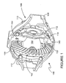
- a toothed crown wheel 102 is fixedly mounted on a differential gear casing 104, which includes a pair of opposing output ends 106 for two rear axle shafts of the vehicle (not shown).
- the crown wheel 102 and casing 104 are rotatably mounted in a carrier having first and second portions 108, 110.
- the crown wheel 102 and casing 104 are rotatably supported on the second portion, via support rings 112. A major proportion of the crown wheel 102 and casing 104 are thereby encased in the first portion 108 of the carrier.
- the carrier defines a major axis of rotation for the rear axle of the vehicle, generally left to right as viewed in Figure 1.
- the crown wheel 102 and casing 104 are concentric with said major axis.
- the second portion 110 of the carrier defines a generally annular end face 114, as can be seen most clearly in Figure 3.
- the first portion 108 of the carrier defines a similar end face, whereby the two end faces are intended to be secured together, for example using an annular weld or bolts, so as to define a main chamber 116 about the crown wheel 102 and casing 104.
- a pinion 118 is rotatable in a bearing 120 provided in the front end of the second portion 110 of the carrier, to the right as viewed in Figure 2.
- the pinion 118 forms the output end of an automotive drive shaft and is arranged in operative mesh with the crown wheel 102.
- the axis of rotation of the pinion 118 is offset from the major axis of the carrier, downwards as viewed in Figure 2.
- a volume of lubricant (omitted from Figures 1 to 4 for clarity purposes) is contained in the carrier, for use in lubricating and cooling the internal components.
- the vehicle drive shaft (not shown) is used to rotate the pinion 118 in its bearing 120, which in turn causes rotation of the crown wheel 102.
- Automotive drive is thereby transmitted to the rear axle shafts via the driving head assembly 100.
- Differential gears inside the casing 104 are configured to enable the rear axle shafts to operate at different rotational speeds when the vehicle is not travelling in a straight line, for example.
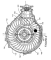
- the driving head assembly 100 as thus far described is fairly conventional. However, as can be seen most clearly in Figures 3 and 4, a shield or housing 130 is fitted over the section of the crown wheel 102 which projects from the second portion 110 of the carrier. The housing 130 is sealingly secured onto the second portion 110 of the carrier, for example via bolts, so as to define a control chamber 132 inside the carrier.
- the walls of the chamber act as a dam for isolating the crown wheel from the main body of lubricant in the carrier.
- the housing 132 is configured to cover a significant proportion of the crown wheel 102.
- the internal shape of the housing 130 is configured to match the general external profile of the crown wheel 102, so as to minimise the free space in the control chamber 132 around the crown wheel 102. As such, it is preferred if only an operative clearance, for example 10 mm, is provided between the internal surface of the housing 130 and the crown wheel 102. A similar clearance is preferred between the internal surface of the housing 130 and the external surface of the casing 104.
- Apertures 134 are provided in upper regions of the housing 130 above the operative axis of rotation of the pinion 118, and more particularly, above the operative centre line of the differential casing 104.
- a control valve 140 is located in a lower region of the housing 130, generally in line with the axis of rotation of the crown wheel 102, for regulating the flow of lubricant between the second portion 110 of the carrier 106 and the control chamber 132.
- a gate valve having a maximum valve aperture of 40 mm diameter extends through a side of the housing 130.
- a lubricant health sensor (not illustrated) is also provided in the lower part of the housing 130, conveniently as part of the control valve 140, for monitoring the temperature and/or viscous quality of the lubricant in the control chamber 132. More preferably, however, the sensor should include a probe which is positioned adjacent the underside of the pinion 118 or the underside of the pinion bearing 120.
- a control unit (not shown), preferably forming part of the vehicle management system, is arranged remote from and in communication with the control valve 140 and the sensor.
- baffles or other flow preventing devices are preferably provided in the carrier to prevent the flow of lubricant into the control chamber 132 via the rear axle shafts, i.e. into the differential casing 104, and vice versa.
- the driving head assembly 100 is shown in a normal stationary condition with the control valve 140 in an open condition. That is to say, the vehicle drive shaft, and hence the pinion 118, crown wheel 102 and casing 104, are not rotating.
- a volume of lubricant in this embodiment 12 litres of high grade oil (indicated by shading), is provided in the carrier to a level indicated at 160, hereinafter referred to as the standing level.
- the standing level 160 maintains a volume of lubricant in contact with at least a lower portion of the pinion bearing 120 to provide cooling thereof.
- the control valve 140 is situated below the standing level 160, whereas the apertures 134 in the control housing 130 and the centre line of the differential casing 104 are above the standing level 160.
- the pinion 118 is rotated, which causes rotation of the crown wheel 102 and the casing 104, clockwise as viewed in Figure 5.
- Lubricant is thus picked up on the teeth of the crown wheel 102 and is thrown out of the control housing 130 in the direction of the pinion 118, from left to right as viewed in Figure 5, into the second portion 110 of the carrier.
- Rotation of the crown wheel 102 and casing 104 also causes churning of the lubricant in the control chamber 132, which results in a volume of lubricant being thrown out of the control housing 130 through the apertures 134 into the first portion 108 of the carrier.
- Lubricant thrown towards the pinion 118 is able to drip down onto an inclined return surface 170 provided below the pinion bearing 120.
- the return surface 170 is configured for re-circulating lubricant back into the second portion 110 of the carrier 106.
- lubricant is expelled from the housing 130 in the manner described above.
- the low position of the valve aperture in the housing 130 ensures that a head of lubricant is maintained outside the housing 130 with respect to the level of lubricant in the control chamber 132.
- lubricant is able to flow through the valve 140 into the control chamber 132 (preferably maintaining the lubricant at or around the standing level 160 inside the chamber 132), so that there is a continual feed of lubricant for the pinion bearing 120.
- housing 130 and control valve 140 can be used to significantly alter level of lubricant in contact with the crown wheel 102, as follows.
- control unit Under stationary conditions, i.e. when the crown wheel is not rotating, the control unit is programmed to hold the control valve 140 in an open position, so that the level of lubricant in the control chamber 132 corresponds to the level of lubricant outside the housing 130, i.e. the standing level 160 ( Figure 5).
- control unit determines that the vehicle is operating in a low torque steady state condition, the control unit is configured to close the control valve 140, to prevent or inhibit the return of lubricant to the control chamber 132 through the valve 140.
- valve 140 can be used to starve the control chamber 132 of re-circulated lubricant.
- the crown wheel 102 is able to rotate within the housing 132 in a substantially unhindered manner. Hence, power losses associated with the churning of the crown wheel and/or differential casing through lubricant are significantly reduced, thereby reducing the real-time fuel consumption of the vehicle.
- the control unit is also configured to re-open the valve 140 if the health sensor detects that the temperature within the carrier exceeds a predetermined threshold, so as to enable lubricant to re-fill the control chamber 132 and provide maximum cooling within the control chamber 132, and more particularly for the pinion bearing 120.
- control unit determines that the vehicle is operating in a high torque steady state condition, the control unit is configured to ensure that the valve 140 is opened or remains open, to equalise the levels of lubricant in the carrier (as shown in Figure 5), and thereby ensure adequate cooling and lubrication of the differential components under high demand conditions.
- control unit control housing 130 and control valve 140 can therefore be used to optimise fuel consumption of the vehicle, dependent upon the operating conditions experienced by the assembly 100.
- the control unit in communication with other control units in the vehicle (e.g. the engine management system, transmission control, retarder) is able to detect the load/speed conditions at which the driving head is working. Based on the working conditions of the driving head and input from the health sensor, the control unit can be configured to optimise the lubricant level in the housing to guarantee both a reduction of churning losses and adequate lubrication of the rotating parts.
- the level of lubricant in the control chamber may drop below the level of the crown wheel 102, thereby removing substantially all standing lubricant, to optimise efficiency.
- a feed of lubricant back into the chamber 132 can then be achieved by controlling the valve 140 only when the pinion bearing 120 is at risk of overheating (i.e. due to a lack if sufficient lubricant).
- the housing may be modified to suit particular requirements.
- an open housing may be provided, thus avoiding the need for the apertures 134.
- a top section of the housing 130 could be removed at a level above the operative axis of rotation of the pinion 118 in use, and more particularly above the operative centre line of the differential casing 104.
- dam walls on either side of the crown wheel are preferred, wherein the walls isolate at least the lower portion of the crown wheel from the main body of lubricant within the carrier are preferred.
- rotation of the crown causes lubricant to splash or be thrown over the walls, thereby reducing the level of lubricant in the dammed region adjacent the crown wheel.
- These may be connected by a transverse wall extending beneath the crown wheel (e.g. In the manner of the shield described above) or may be separate from one another, e.g. individual upstanding from the carrier.
- a valve or other flow control means in at least one of the walls can then be operated to regulate the level of lubricant in the dammed region. The valve is controlled in response to temperature and/or vehicle driving conditions.
- the valve itself may be temperature sensitive, thereby negating the need for a separate temperature sensor (e.g. the health sensor referred to above). Where a separate temperature sensor is used, this is preferably positioned adjacent the pinion bearing.
- a heater may also be provided in the carrier 106 to reduce the viscosity of the lubricant in low temperature environments.
- the control unit may communicate with the health sensor to detect the temperature of the lubricant in the carrier. If the control unit determines that the temperature is too low, then the control unit can initiate power to the heater to raise the temperature to the required level, e.g. to keep the oil in a suitably fluid state, to further minimise churning losses associated with the crown wheel 102 and casing 104.
- the shield and methods described above are applicable to all driving head assemblies, not only those for heavy goods vehicles.
Landscapes
- Engineering & Computer Science (AREA)
- General Engineering & Computer Science (AREA)
- Mechanical Engineering (AREA)
- General Details Of Gearings (AREA)
- Body Structure For Vehicles (AREA)
- Vehicle Body Suspensions (AREA)
Applications Claiming Priority (1)
| Application Number | Priority Date | Filing Date | Title |
|---|---|---|---|
| GBGB0621351.6A GB0621351D0 (en) | 2006-10-26 | 2006-10-26 | Lubricant level control in vehicle driving head assemblies |
Publications (3)
| Publication Number | Publication Date |
|---|---|
| EP1918613A2 true EP1918613A2 (de) | 2008-05-07 |
| EP1918613A3 EP1918613A3 (de) | 2008-06-18 |
| EP1918613B1 EP1918613B1 (de) | 2010-01-20 |
Family
ID=37546051
Family Applications (1)
| Application Number | Title | Priority Date | Filing Date |
|---|---|---|---|
| EP07254256A Active EP1918613B1 (de) | 2006-10-26 | 2007-10-26 | Schmiermittelstandregelung bei Antriebskopfanordnungen von Fahrzeugen |
Country Status (4)
| Country | Link |
|---|---|
| EP (1) | EP1918613B1 (de) |
| AT (1) | ATE455982T1 (de) |
| DE (1) | DE602007004407D1 (de) |
| GB (1) | GB0621351D0 (de) |
Cited By (14)
| Publication number | Priority date | Publication date | Assignee | Title |
|---|---|---|---|---|
| EP2270364A1 (de) | 2009-06-30 | 2011-01-05 | Meritor Technology, Inc. | Achse |
| EP2270365A1 (de) * | 2009-06-30 | 2011-01-05 | Meritor Technology, Inc. | Verfahren zur Steuerung des Betriebs eines Fahrzeugs |
| CN101936383A (zh) * | 2009-06-30 | 2011-01-05 | 美驰技术有限责任公司 | 传动系统 |
| DE102012004279A1 (de) * | 2012-03-01 | 2013-05-29 | Daimler Ag | Achsgetriebe für ein Kraftfahrzeug |
| US8672094B2 (en) | 2009-01-19 | 2014-03-18 | Magna Powertrain Ag & Co Kg | Transmission with lubrication device |
| DE102013202594A1 (de) | 2013-02-19 | 2014-08-21 | Zf Friedrichshafen Ag | Antriebseinrichtung für die Laufräder eines Fahrzeugs |
| EP2801737A1 (de) | 2013-05-08 | 2014-11-12 | Meritor Technology, LLC | Achsenanordnung und Verfahren zum Umrüsten einer Achsenanordnung |
| WO2015092471A1 (en) * | 2013-12-20 | 2015-06-25 | Volvo Truck Corporation | Differential arrangement and driven axle and automotive vehicle with improved lubrication |
| JP2016041979A (ja) * | 2014-03-10 | 2016-03-31 | 本田技研工業株式会社 | デファレンシャル装置の潤滑構造 |
| WO2017207215A1 (de) * | 2016-06-01 | 2017-12-07 | Voith Patent Gmbh | Stirnradgetriebe |
| US10190673B2 (en) | 2016-11-30 | 2019-01-29 | Dana Heavy Vehicle Systems, Llc | Active oil management system for axles |
| CN114877058A (zh) * | 2022-05-31 | 2022-08-09 | 中国第一汽车股份有限公司 | 车辆控制方法、装置、终端设备及存储介质 |
| DE102021106066A1 (de) | 2021-03-12 | 2022-09-15 | Schaeffler Technologies AG & Co. KG | Elektrisch betreibbarer Antriebsstrang |
| CN115698553A (zh) * | 2020-06-10 | 2023-02-03 | 采埃孚股份公司 | 用于机动车的传动装置 |
Families Citing this family (3)
| Publication number | Priority date | Publication date | Assignee | Title |
|---|---|---|---|---|
| WO2014066581A1 (en) | 2012-10-26 | 2014-05-01 | Dana Automotive Systems Group, Llc | Lubricant management system |
| US9683649B2 (en) | 2015-04-22 | 2017-06-20 | Ford Global Technologies, Llc | Vehicle and insulating device for gearbox |
| US11421773B1 (en) | 2021-02-15 | 2022-08-23 | Fca Us Llc | Vehicle drivetrain lubrication system |
Citations (2)
| Publication number | Priority date | Publication date | Assignee | Title |
|---|---|---|---|---|
| EP0696697A1 (de) | 1994-08-12 | 1996-02-14 | Toyota Jidosha Kabushiki Kaisha | Einrichtung zur wirksamen Schmierung eines Kraftübertragungssystems in einem Kraftfahrzeug bei der Inbetriebnahme des Kraftfahrzeugs |
| US6299561B1 (en) | 1999-07-21 | 2001-10-09 | Meritor Heavy Vehicle Systems, Llc | Device for controlling level of gear lubricant as a function of speed |
Family Cites Families (5)
| Publication number | Priority date | Publication date | Assignee | Title |
|---|---|---|---|---|
| US5209399A (en) * | 1992-06-11 | 1993-05-11 | Texas Instruments Incorporated | Automotive oil level control valve apparatus |
| JP3001858B1 (ja) * | 1998-08-18 | 2000-01-24 | 本田技研工業株式会社 | 潤滑油圧制御装置 |
| DE10157714A1 (de) * | 2001-11-24 | 2003-06-26 | Daimler Chrysler Ag | Verfahren und Vorrichtungen zur Durchführung des Verfahrens zum Beeinflussen der Betriebstemperatur eines hydraulischen Betriebsmittels für ein Antriebsaggregat eines Fahrzeuges |
| DE10359505A1 (de) * | 2003-12-18 | 2005-07-14 | Bayerische Motoren Werke Ag | Getriebe mit einem sich in Abhängigkeit von der Getriebeöltemperatur dehnenden Dehnkörper |
| DE102005007386A1 (de) * | 2005-02-18 | 2006-08-31 | Zf Friedrichshafen Ag | Verfahren und Einrichtung zur Befüllung des Ölausgleichsbehälters eines Getriebes |
-
2006
- 2006-10-26 GB GBGB0621351.6A patent/GB0621351D0/en not_active Ceased
-
2007
- 2007-10-26 AT AT07254256T patent/ATE455982T1/de not_active IP Right Cessation
- 2007-10-26 EP EP07254256A patent/EP1918613B1/de active Active
- 2007-10-26 DE DE602007004407T patent/DE602007004407D1/de active Active
Patent Citations (2)
| Publication number | Priority date | Publication date | Assignee | Title |
|---|---|---|---|---|
| EP0696697A1 (de) | 1994-08-12 | 1996-02-14 | Toyota Jidosha Kabushiki Kaisha | Einrichtung zur wirksamen Schmierung eines Kraftübertragungssystems in einem Kraftfahrzeug bei der Inbetriebnahme des Kraftfahrzeugs |
| US6299561B1 (en) | 1999-07-21 | 2001-10-09 | Meritor Heavy Vehicle Systems, Llc | Device for controlling level of gear lubricant as a function of speed |
Cited By (31)
| Publication number | Priority date | Publication date | Assignee | Title |
|---|---|---|---|---|
| US8672094B2 (en) | 2009-01-19 | 2014-03-18 | Magna Powertrain Ag & Co Kg | Transmission with lubrication device |
| US8360915B2 (en) | 2009-06-30 | 2013-01-29 | Meritor Technology, Inc. | Axle |
| CN101936448A (zh) * | 2009-06-30 | 2011-01-05 | 美驰技术有限责任公司 | 车桥 |
| CN101936383A (zh) * | 2009-06-30 | 2011-01-05 | 美驰技术有限责任公司 | 传动系统 |
| EP2278191A2 (de) | 2009-06-30 | 2011-01-26 | Meritor Technology, Inc. | Zahnradgetriebe mit Schmiermittelpumpe und Schmiermittelreservoir |
| EP2278191A3 (de) * | 2009-06-30 | 2011-02-16 | Meritor Technology, Inc. | Zahnradgetriebe mit Schmiermittelpumpe und Schmiermittelreservoir |
| CN101936448B (zh) * | 2009-06-30 | 2015-06-03 | 美驰技术有限责任公司 | 车桥 |
| EP2270364A1 (de) | 2009-06-30 | 2011-01-05 | Meritor Technology, Inc. | Achse |
| EP2667055A1 (de) * | 2009-06-30 | 2013-11-27 | Meritor Technology, Inc. | Verfahren zur Steuerung des Ölpegels eines Fahrzeugsgetriebes |
| EP2667054A1 (de) * | 2009-06-30 | 2013-11-27 | Meritor Technology, Inc. | Verfahren zur Steuerung des Ölpegels eines Fahrzeugsgetriebes |
| EP2667056A1 (de) * | 2009-06-30 | 2013-11-27 | Meritor Technology, Inc. | Verfahren zur Steuerung des Ölpegels eines Fahrzeugsgetriebes |
| EP2270365A1 (de) * | 2009-06-30 | 2011-01-05 | Meritor Technology, Inc. | Verfahren zur Steuerung des Betriebs eines Fahrzeugs |
| US9377099B2 (en) | 2009-06-30 | 2016-06-28 | Meritor Technology, Inc. | Transmission system |
| CN101936383B (zh) * | 2009-06-30 | 2015-11-25 | 美驰技术有限责任公司 | 传动系统 |
| DE102012004279A1 (de) * | 2012-03-01 | 2013-05-29 | Daimler Ag | Achsgetriebe für ein Kraftfahrzeug |
| US9115798B2 (en) | 2013-02-19 | 2015-08-25 | Zf Friedrichshafen Ag | Drive device for the road wheels of a vehicle |
| DE102013202594A1 (de) | 2013-02-19 | 2014-08-21 | Zf Friedrichshafen Ag | Antriebseinrichtung für die Laufräder eines Fahrzeugs |
| EP2801737A1 (de) | 2013-05-08 | 2014-11-12 | Meritor Technology, LLC | Achsenanordnung und Verfahren zum Umrüsten einer Achsenanordnung |
| US9309961B2 (en) | 2013-05-08 | 2016-04-12 | Meritor Technology, Llc | Axle assembly |
| WO2015092471A1 (en) * | 2013-12-20 | 2015-06-25 | Volvo Truck Corporation | Differential arrangement and driven axle and automotive vehicle with improved lubrication |
| JP2016041979A (ja) * | 2014-03-10 | 2016-03-31 | 本田技研工業株式会社 | デファレンシャル装置の潤滑構造 |
| US9803741B2 (en) | 2014-03-10 | 2017-10-31 | Honda Motor Co., Ltd. | Lubricating structure for differential device |
| CN109196251A (zh) * | 2016-06-01 | 2019-01-11 | 福伊特专利有限公司 | 正齿轮传动器 |
| WO2017207215A1 (de) * | 2016-06-01 | 2017-12-07 | Voith Patent Gmbh | Stirnradgetriebe |
| US10816081B2 (en) | 2016-06-01 | 2020-10-27 | Voith Patent Gmbh | Spur gear transmission |
| CN109196251B (zh) * | 2016-06-01 | 2022-02-08 | 福伊特专利有限公司 | 正齿轮传动器 |
| EP3464951B1 (de) * | 2016-06-01 | 2022-04-06 | Voith Patent GmbH | Stirnradgetriebe |
| US10190673B2 (en) | 2016-11-30 | 2019-01-29 | Dana Heavy Vehicle Systems, Llc | Active oil management system for axles |
| CN115698553A (zh) * | 2020-06-10 | 2023-02-03 | 采埃孚股份公司 | 用于机动车的传动装置 |
| DE102021106066A1 (de) | 2021-03-12 | 2022-09-15 | Schaeffler Technologies AG & Co. KG | Elektrisch betreibbarer Antriebsstrang |
| CN114877058A (zh) * | 2022-05-31 | 2022-08-09 | 中国第一汽车股份有限公司 | 车辆控制方法、装置、终端设备及存储介质 |
Also Published As
| Publication number | Publication date |
|---|---|
| DE602007004407D1 (de) | 2010-03-11 |
| EP1918613A3 (de) | 2008-06-18 |
| EP1918613B1 (de) | 2010-01-20 |
| ATE455982T1 (de) | 2010-02-15 |
| GB0621351D0 (en) | 2006-12-06 |
Similar Documents
| Publication | Publication Date | Title |
|---|---|---|
| EP1918613B1 (de) | Schmiermittelstandregelung bei Antriebskopfanordnungen von Fahrzeugen | |
| EP2659166B1 (de) | Schmiersystem für ein differentialgetriebe für eine angetriebene achse und kraftfahrzeug mit einem solchen schmiersystem | |
| EP2278191B1 (de) | Zahnradgetriebe mit Schmiermittelpumpe und Schmiermittelreservoir | |
| US6299561B1 (en) | Device for controlling level of gear lubricant as a function of speed | |
| EP0763676B1 (de) | Antriebsachse mit Schmierölkühlsystem | |
| CN100478590C (zh) | 用于驱动桥总成的改进润滑系统 | |
| US9249873B2 (en) | Power transmitting component with torque transfer device configured with drag reduction system | |
| EP2660493A1 (de) | Achsenanordnung mit Schmiermittelreservoirmodul | |
| EP2988026B1 (de) | Achsenanordnung | |
| EP3098478B1 (de) | Achsanordnung mit einem dammmodul | |
| GB2471653A (en) | A method of controlling a fluid level around a transmission gear | |
| US10179478B2 (en) | Axle assembly for drive device of a motor vehicle | |
| EP2270364B1 (de) | Achse | |
| US5453181A (en) | Device for a gear | |
| JP2008279826A (ja) | 車両用駆動装置 | |
| KR101195901B1 (ko) | 액슬 어셈블리 내의 피니언 유닛 | |
| CN101988571A (zh) | 包括刮油器的转矩传递装置 | |
| JPH0220527Y2 (de) | ||
| DE102005006811B4 (de) | Getriebe mit Miniaturmotor zur Steuerung des Ölstroms | |
| EP3992497B1 (de) | Achsanordnung mit variabler schmiermitteldrossel | |
| JP2006275163A (ja) | 車両変速機の潤滑油面調整装置 | |
| CN117302085A (zh) | 驱动桥润滑结构和汽车 | |
| US20050005731A1 (en) | Axle housing with reduced lubricant capacity | |
| JP2007263139A (ja) | デファレンシャル装置の潤滑構造 | |
| JPH0638205Y2 (ja) | トランスミッション内のオイルコントロール装置 |
Legal Events
| Date | Code | Title | Description |
|---|---|---|---|
| PUAI | Public reference made under article 153(3) epc to a published international application that has entered the european phase |
Free format text: ORIGINAL CODE: 0009012 |
|
| AK | Designated contracting states |
Kind code of ref document: A2 Designated state(s): AT BE BG CH CY CZ DE DK EE ES FI FR GB GR HU IE IS IT LI LT LU LV MC MT NL PL PT RO SE SI SK TR |
|
| AX | Request for extension of the european patent |
Extension state: AL BA HR MK RS |
|
| PUAL | Search report despatched |
Free format text: ORIGINAL CODE: 0009013 |
|
| AK | Designated contracting states |
Kind code of ref document: A3 Designated state(s): AT BE BG CH CY CZ DE DK EE ES FI FR GB GR HU IE IS IT LI LT LU LV MC MT NL PL PT RO SE SI SK TR |
|
| AX | Request for extension of the european patent |
Extension state: AL BA HR MK RS |
|
| 17P | Request for examination filed |
Effective date: 20081216 |
|
| 17Q | First examination report despatched |
Effective date: 20090115 |
|
| AKX | Designation fees paid |
Designated state(s): AT BE BG CH CY CZ DE DK EE ES FI FR GB GR HU IE IS IT LI LT LU LV MC MT NL PL PT RO SE SI SK TR |
|
| GRAP | Despatch of communication of intention to grant a patent |
Free format text: ORIGINAL CODE: EPIDOSNIGR1 |
|
| GRAS | Grant fee paid |
Free format text: ORIGINAL CODE: EPIDOSNIGR3 |
|
| GRAA | (expected) grant |
Free format text: ORIGINAL CODE: 0009210 |
|
| AK | Designated contracting states |
Kind code of ref document: B1 Designated state(s): AT BE BG CH CY CZ DE DK EE ES FI FR GB GR HU IE IS IT LI LT LU LV MC MT NL PL PT RO SE SI SK TR |
|
| REG | Reference to a national code |
Ref country code: GB Ref legal event code: FG4D |
|
| REG | Reference to a national code |
Ref country code: CH Ref legal event code: EP |
|
| REG | Reference to a national code |
Ref country code: IE Ref legal event code: FG4D |
|
| REF | Corresponds to: |
Ref document number: 602007004407 Country of ref document: DE Date of ref document: 20100311 Kind code of ref document: P |
|
| REG | Reference to a national code |
Ref country code: SE Ref legal event code: TRGR |
|
| REG | Reference to a national code |
Ref country code: NL Ref legal event code: VDEP Effective date: 20100120 |
|
| LTIE | Lt: invalidation of european patent or patent extension |
Effective date: 20100120 |
|
| PG25 | Lapsed in a contracting state [announced via postgrant information from national office to epo] |
Ref country code: AT Free format text: LAPSE BECAUSE OF FAILURE TO SUBMIT A TRANSLATION OF THE DESCRIPTION OR TO PAY THE FEE WITHIN THE PRESCRIBED TIME-LIMIT Effective date: 20100120 |
|
| PG25 | Lapsed in a contracting state [announced via postgrant information from national office to epo] |
Ref country code: ES Free format text: LAPSE BECAUSE OF FAILURE TO SUBMIT A TRANSLATION OF THE DESCRIPTION OR TO PAY THE FEE WITHIN THE PRESCRIBED TIME-LIMIT Effective date: 20100501 Ref country code: PT Free format text: LAPSE BECAUSE OF FAILURE TO SUBMIT A TRANSLATION OF THE DESCRIPTION OR TO PAY THE FEE WITHIN THE PRESCRIBED TIME-LIMIT Effective date: 20100520 Ref country code: IS Free format text: LAPSE BECAUSE OF FAILURE TO SUBMIT A TRANSLATION OF THE DESCRIPTION OR TO PAY THE FEE WITHIN THE PRESCRIBED TIME-LIMIT Effective date: 20100520 Ref country code: NL Free format text: LAPSE BECAUSE OF FAILURE TO SUBMIT A TRANSLATION OF THE DESCRIPTION OR TO PAY THE FEE WITHIN THE PRESCRIBED TIME-LIMIT Effective date: 20100120 Ref country code: LT Free format text: LAPSE BECAUSE OF FAILURE TO SUBMIT A TRANSLATION OF THE DESCRIPTION OR TO PAY THE FEE WITHIN THE PRESCRIBED TIME-LIMIT Effective date: 20100120 |
|
| PG25 | Lapsed in a contracting state [announced via postgrant information from national office to epo] |
Ref country code: LV Free format text: LAPSE BECAUSE OF FAILURE TO SUBMIT A TRANSLATION OF THE DESCRIPTION OR TO PAY THE FEE WITHIN THE PRESCRIBED TIME-LIMIT Effective date: 20100120 Ref country code: FI Free format text: LAPSE BECAUSE OF FAILURE TO SUBMIT A TRANSLATION OF THE DESCRIPTION OR TO PAY THE FEE WITHIN THE PRESCRIBED TIME-LIMIT Effective date: 20100120 Ref country code: SI Free format text: LAPSE BECAUSE OF FAILURE TO SUBMIT A TRANSLATION OF THE DESCRIPTION OR TO PAY THE FEE WITHIN THE PRESCRIBED TIME-LIMIT Effective date: 20100120 Ref country code: PL Free format text: LAPSE BECAUSE OF FAILURE TO SUBMIT A TRANSLATION OF THE DESCRIPTION OR TO PAY THE FEE WITHIN THE PRESCRIBED TIME-LIMIT Effective date: 20100120 |
|
| PG25 | Lapsed in a contracting state [announced via postgrant information from national office to epo] |
Ref country code: CY Free format text: LAPSE BECAUSE OF FAILURE TO SUBMIT A TRANSLATION OF THE DESCRIPTION OR TO PAY THE FEE WITHIN THE PRESCRIBED TIME-LIMIT Effective date: 20100120 Ref country code: RO Free format text: LAPSE BECAUSE OF FAILURE TO SUBMIT A TRANSLATION OF THE DESCRIPTION OR TO PAY THE FEE WITHIN THE PRESCRIBED TIME-LIMIT Effective date: 20100120 Ref country code: GR Free format text: LAPSE BECAUSE OF FAILURE TO SUBMIT A TRANSLATION OF THE DESCRIPTION OR TO PAY THE FEE WITHIN THE PRESCRIBED TIME-LIMIT Effective date: 20100421 Ref country code: EE Free format text: LAPSE BECAUSE OF FAILURE TO SUBMIT A TRANSLATION OF THE DESCRIPTION OR TO PAY THE FEE WITHIN THE PRESCRIBED TIME-LIMIT Effective date: 20100120 |
|
| PLBE | No opposition filed within time limit |
Free format text: ORIGINAL CODE: 0009261 |
|
| STAA | Information on the status of an ep patent application or granted ep patent |
Free format text: STATUS: NO OPPOSITION FILED WITHIN TIME LIMIT |
|
| PG25 | Lapsed in a contracting state [announced via postgrant information from national office to epo] |
Ref country code: BG Free format text: LAPSE BECAUSE OF FAILURE TO SUBMIT A TRANSLATION OF THE DESCRIPTION OR TO PAY THE FEE WITHIN THE PRESCRIBED TIME-LIMIT Effective date: 20100420 Ref country code: SK Free format text: LAPSE BECAUSE OF FAILURE TO SUBMIT A TRANSLATION OF THE DESCRIPTION OR TO PAY THE FEE WITHIN THE PRESCRIBED TIME-LIMIT Effective date: 20100120 |
|
| 26N | No opposition filed |
Effective date: 20101021 |
|
| PG25 | Lapsed in a contracting state [announced via postgrant information from national office to epo] |
Ref country code: DK Free format text: LAPSE BECAUSE OF FAILURE TO SUBMIT A TRANSLATION OF THE DESCRIPTION OR TO PAY THE FEE WITHIN THE PRESCRIBED TIME-LIMIT Effective date: 20100120 |
|
| PG25 | Lapsed in a contracting state [announced via postgrant information from national office to epo] |
Ref country code: MC Free format text: LAPSE BECAUSE OF NON-PAYMENT OF DUE FEES Effective date: 20101031 |
|
| PG25 | Lapsed in a contracting state [announced via postgrant information from national office to epo] |
Ref country code: IE Free format text: LAPSE BECAUSE OF NON-PAYMENT OF DUE FEES Effective date: 20101026 |
|
| PG25 | Lapsed in a contracting state [announced via postgrant information from national office to epo] |
Ref country code: IT Free format text: LAPSE BECAUSE OF NON-PAYMENT OF DUE FEES Effective date: 20101026 Ref country code: MT Free format text: LAPSE BECAUSE OF FAILURE TO SUBMIT A TRANSLATION OF THE DESCRIPTION OR TO PAY THE FEE WITHIN THE PRESCRIBED TIME-LIMIT Effective date: 20100120 |
|
| REG | Reference to a national code |
Ref country code: CH Ref legal event code: PL |
|
| GBPC | Gb: european patent ceased through non-payment of renewal fee |
Effective date: 20111026 |
|
| PG25 | Lapsed in a contracting state [announced via postgrant information from national office to epo] |
Ref country code: LI Free format text: LAPSE BECAUSE OF NON-PAYMENT OF DUE FEES Effective date: 20111031 Ref country code: CH Free format text: LAPSE BECAUSE OF NON-PAYMENT OF DUE FEES Effective date: 20111031 |
|
| PG25 | Lapsed in a contracting state [announced via postgrant information from national office to epo] |
Ref country code: GB Free format text: LAPSE BECAUSE OF NON-PAYMENT OF DUE FEES Effective date: 20111026 |
|
| PG25 | Lapsed in a contracting state [announced via postgrant information from national office to epo] |
Ref country code: HU Free format text: LAPSE BECAUSE OF FAILURE TO SUBMIT A TRANSLATION OF THE DESCRIPTION OR TO PAY THE FEE WITHIN THE PRESCRIBED TIME-LIMIT Effective date: 20100721 Ref country code: LU Free format text: LAPSE BECAUSE OF NON-PAYMENT OF DUE FEES Effective date: 20101026 |
|
| PG25 | Lapsed in a contracting state [announced via postgrant information from national office to epo] |
Ref country code: TR Free format text: LAPSE BECAUSE OF FAILURE TO SUBMIT A TRANSLATION OF THE DESCRIPTION OR TO PAY THE FEE WITHIN THE PRESCRIBED TIME-LIMIT Effective date: 20100120 |
|
| REG | Reference to a national code |
Ref country code: FR Ref legal event code: PLFP Year of fee payment: 9 |
|
| REG | Reference to a national code |
Ref country code: FR Ref legal event code: PLFP Year of fee payment: 10 |
|
| REG | Reference to a national code |
Ref country code: FR Ref legal event code: PLFP Year of fee payment: 11 |
|
| REG | Reference to a national code |
Ref country code: FR Ref legal event code: PLFP Year of fee payment: 12 |
|
| P01 | Opt-out of the competence of the unified patent court (upc) registered |
Effective date: 20230531 |
|
| PGFP | Annual fee paid to national office [announced via postgrant information from national office to epo] |
Ref country code: DE Payment date: 20251029 Year of fee payment: 19 |
|
| PGFP | Annual fee paid to national office [announced via postgrant information from national office to epo] |
Ref country code: IT Payment date: 20251021 Year of fee payment: 19 |
|
| PGFP | Annual fee paid to national office [announced via postgrant information from national office to epo] |
Ref country code: FR Payment date: 20251027 Year of fee payment: 19 |
|
| PGFP | Annual fee paid to national office [announced via postgrant information from national office to epo] |
Ref country code: BE Payment date: 20251027 Year of fee payment: 19 |
|
| PGFP | Annual fee paid to national office [announced via postgrant information from national office to epo] |
Ref country code: SE Payment date: 20251027 Year of fee payment: 19 |
|
| PGFP | Annual fee paid to national office [announced via postgrant information from national office to epo] |
Ref country code: CZ Payment date: 20251006 Year of fee payment: 19 |