EP0696697A1 - Einrichtung zur wirksamen Schmierung eines Kraftübertragungssystems in einem Kraftfahrzeug bei der Inbetriebnahme des Kraftfahrzeugs - Google Patents
Einrichtung zur wirksamen Schmierung eines Kraftübertragungssystems in einem Kraftfahrzeug bei der Inbetriebnahme des Kraftfahrzeugs Download PDFInfo
- Publication number
- EP0696697A1 EP0696697A1 EP95112588A EP95112588A EP0696697A1 EP 0696697 A1 EP0696697 A1 EP 0696697A1 EP 95112588 A EP95112588 A EP 95112588A EP 95112588 A EP95112588 A EP 95112588A EP 0696697 A1 EP0696697 A1 EP 0696697A1
- Authority
- EP
- European Patent Office
- Prior art keywords
- oil
- lubricating
- transmission system
- power transmission
- pump
- Prior art date
- Legal status (The legal status is an assumption and is not a legal conclusion. Google has not performed a legal analysis and makes no representation as to the accuracy of the status listed.)
- Granted
Links
- 230000005540 biological transmission Effects 0.000 title claims abstract description 249
- 238000005461 lubrication Methods 0.000 title claims description 65
- 239000003921 oil Substances 0.000 claims abstract description 466
- 239000010687 lubricating oil Substances 0.000 claims abstract description 329
- 230000001050 lubricating effect Effects 0.000 claims abstract description 299
- 230000002401 inhibitory effect Effects 0.000 claims description 7
- 230000001105 regulatory effect Effects 0.000 claims description 6
- 238000007599 discharging Methods 0.000 claims 4
- 238000013019 agitation Methods 0.000 description 18
- 101150028119 SPD1 gene Proteins 0.000 description 17
- 230000002829 reductive effect Effects 0.000 description 16
- 230000001276 controlling effect Effects 0.000 description 10
- 206010010904 Convulsion Diseases 0.000 description 9
- 230000007423 decrease Effects 0.000 description 9
- 230000008859 change Effects 0.000 description 8
- 238000010586 diagram Methods 0.000 description 7
- 230000009467 reduction Effects 0.000 description 6
- 239000012530 fluid Substances 0.000 description 5
- 230000005484 gravity Effects 0.000 description 5
- 238000012423 maintenance Methods 0.000 description 5
- 230000000694 effects Effects 0.000 description 4
- 238000013021 overheating Methods 0.000 description 4
- 230000008901 benefit Effects 0.000 description 3
- 230000006872 improvement Effects 0.000 description 3
- 238000004519 manufacturing process Methods 0.000 description 3
- 238000003825 pressing Methods 0.000 description 3
- 238000010276 construction Methods 0.000 description 2
- 230000000994 depressogenic effect Effects 0.000 description 2
- 230000006870 function Effects 0.000 description 2
- 230000004048 modification Effects 0.000 description 2
- 238000012986 modification Methods 0.000 description 2
- 230000000717 retained effect Effects 0.000 description 2
- 230000002441 reversible effect Effects 0.000 description 2
- 230000001133 acceleration Effects 0.000 description 1
- 230000003247 decreasing effect Effects 0.000 description 1
- 230000006866 deterioration Effects 0.000 description 1
- 230000036316 preload Effects 0.000 description 1
- 230000002035 prolonged effect Effects 0.000 description 1
- 238000003860 storage Methods 0.000 description 1
Images




Classifications
-
- F—MECHANICAL ENGINEERING; LIGHTING; HEATING; WEAPONS; BLASTING
- F16—ENGINEERING ELEMENTS AND UNITS; GENERAL MEASURES FOR PRODUCING AND MAINTAINING EFFECTIVE FUNCTIONING OF MACHINES OR INSTALLATIONS; THERMAL INSULATION IN GENERAL
- F16H—GEARING
- F16H57/00—General details of gearing
- F16H57/04—Features relating to lubrication or cooling or heating
- F16H57/0447—Control of lubricant levels, e.g. lubricant level control dependent on temperature
-
- B—PERFORMING OPERATIONS; TRANSPORTING
- B62—LAND VEHICLES FOR TRAVELLING OTHERWISE THAN ON RAILS
- B62D—MOTOR VEHICLES; TRAILERS
- B62D5/00—Power-assisted or power-driven steering
- B62D5/06—Power-assisted or power-driven steering fluid, i.e. using a pressurised fluid for most or all the force required for steering a vehicle
- B62D5/07—Supply of pressurised fluid for steering also supplying other consumers ; control thereof
-
- F—MECHANICAL ENGINEERING; LIGHTING; HEATING; WEAPONS; BLASTING
- F16—ENGINEERING ELEMENTS AND UNITS; GENERAL MEASURES FOR PRODUCING AND MAINTAINING EFFECTIVE FUNCTIONING OF MACHINES OR INSTALLATIONS; THERMAL INSULATION IN GENERAL
- F16H—GEARING
- F16H61/00—Control functions within control units of change-speed- or reversing-gearings for conveying rotary motion ; Control of exclusively fluid gearing, friction gearing, gearings with endless flexible members or other particular types of gearing
- F16H61/0021—Generation or control of line pressure
- F16H61/0025—Supply of control fluid; Pumps therefor
-
- F—MECHANICAL ENGINEERING; LIGHTING; HEATING; WEAPONS; BLASTING
- F16—ENGINEERING ELEMENTS AND UNITS; GENERAL MEASURES FOR PRODUCING AND MAINTAINING EFFECTIVE FUNCTIONING OF MACHINES OR INSTALLATIONS; THERMAL INSULATION IN GENERAL
- F16N—LUBRICATING
- F16N7/00—Arrangements for supplying oil or unspecified lubricant from a stationary reservoir or the equivalent in or on the machine or member to be lubricated
- F16N7/38—Arrangements for supplying oil or unspecified lubricant from a stationary reservoir or the equivalent in or on the machine or member to be lubricated with a separate pump; Central lubrication systems
- F16N7/40—Arrangements for supplying oil or unspecified lubricant from a stationary reservoir or the equivalent in or on the machine or member to be lubricated with a separate pump; Central lubrication systems in a closed circulation system
-
- B—PERFORMING OPERATIONS; TRANSPORTING
- B60—VEHICLES IN GENERAL
- B60K—ARRANGEMENT OR MOUNTING OF PROPULSION UNITS OR OF TRANSMISSIONS IN VEHICLES; ARRANGEMENT OR MOUNTING OF PLURAL DIVERSE PRIME-MOVERS IN VEHICLES; AUXILIARY DRIVES FOR VEHICLES; INSTRUMENTATION OR DASHBOARDS FOR VEHICLES; ARRANGEMENTS IN CONNECTION WITH COOLING, AIR INTAKE, GAS EXHAUST OR FUEL SUPPLY OF PROPULSION UNITS IN VEHICLES
- B60K1/00—Arrangement or mounting of electrical propulsion units
-
- F—MECHANICAL ENGINEERING; LIGHTING; HEATING; WEAPONS; BLASTING
- F16—ENGINEERING ELEMENTS AND UNITS; GENERAL MEASURES FOR PRODUCING AND MAINTAINING EFFECTIVE FUNCTIONING OF MACHINES OR INSTALLATIONS; THERMAL INSULATION IN GENERAL
- F16H—GEARING
- F16H2312/00—Driving activities
- F16H2312/14—Going to, or coming from standby operation, e.g. for engine start-stop operation at traffic lights
-
- F—MECHANICAL ENGINEERING; LIGHTING; HEATING; WEAPONS; BLASTING
- F16—ENGINEERING ELEMENTS AND UNITS; GENERAL MEASURES FOR PRODUCING AND MAINTAINING EFFECTIVE FUNCTIONING OF MACHINES OR INSTALLATIONS; THERMAL INSULATION IN GENERAL
- F16H—GEARING
- F16H48/00—Differential gearings
- F16H48/06—Differential gearings with gears having orbital motion
- F16H48/08—Differential gearings with gears having orbital motion comprising bevel gears
-
- F—MECHANICAL ENGINEERING; LIGHTING; HEATING; WEAPONS; BLASTING
- F16—ENGINEERING ELEMENTS AND UNITS; GENERAL MEASURES FOR PRODUCING AND MAINTAINING EFFECTIVE FUNCTIONING OF MACHINES OR INSTALLATIONS; THERMAL INSULATION IN GENERAL
- F16H—GEARING
- F16H57/00—General details of gearing
- F16H57/04—Features relating to lubrication or cooling or heating
- F16H57/0409—Features relating to lubrication or cooling or heating characterised by increasing efficiency, e.g. by reducing splash losses
-
- F—MECHANICAL ENGINEERING; LIGHTING; HEATING; WEAPONS; BLASTING
- F16—ENGINEERING ELEMENTS AND UNITS; GENERAL MEASURES FOR PRODUCING AND MAINTAINING EFFECTIVE FUNCTIONING OF MACHINES OR INSTALLATIONS; THERMAL INSULATION IN GENERAL
- F16H—GEARING
- F16H57/00—General details of gearing
- F16H57/04—Features relating to lubrication or cooling or heating
- F16H57/045—Lubricant storage reservoirs, e.g. reservoirs in addition to a gear sump for collecting lubricant in the upper part of a gear case
-
- F—MECHANICAL ENGINEERING; LIGHTING; HEATING; WEAPONS; BLASTING
- F16—ENGINEERING ELEMENTS AND UNITS; GENERAL MEASURES FOR PRODUCING AND MAINTAINING EFFECTIVE FUNCTIONING OF MACHINES OR INSTALLATIONS; THERMAL INSULATION IN GENERAL
- F16H—GEARING
- F16H57/00—General details of gearing
- F16H57/04—Features relating to lubrication or cooling or heating
- F16H57/048—Type of gearings to be lubricated, cooled or heated
- F16H57/0482—Gearings with gears having orbital motion
- F16H57/0483—Axle or inter-axle differentials
-
- Y—GENERAL TAGGING OF NEW TECHNOLOGICAL DEVELOPMENTS; GENERAL TAGGING OF CROSS-SECTIONAL TECHNOLOGIES SPANNING OVER SEVERAL SECTIONS OF THE IPC; TECHNICAL SUBJECTS COVERED BY FORMER USPC CROSS-REFERENCE ART COLLECTIONS [XRACs] AND DIGESTS
- Y10—TECHNICAL SUBJECTS COVERED BY FORMER USPC
- Y10T—TECHNICAL SUBJECTS COVERED BY FORMER US CLASSIFICATION
- Y10T74/00—Machine element or mechanism
- Y10T74/19—Gearing
- Y10T74/19991—Lubrication
Definitions
- the present invention relates in general to a lubricating device for a power transmission system of a motor vehicle wherein all rotating members are at rest upon stopping of the vehicle, and more particularly to such a lubricating device utilizing a mechanical pump which is driven by the power transmission system.
- a power transmission system such as a transmission, a speed reducing device or a differential gear device used in a motor vehicle is equipped with a lubricating device for lubricating various rotating members of the power transmission system so as to protect bearing portions and mutually meshing portions of the rotating members from seizure and early wearing.
- a lubricating device for the vehicle power transmission system.
- so-called "oil bath lubrication” is known, wherein portions of the power transmission system are immersed in a lubricating oil stored in a suitable oil pan, and the lubricating oil is scattered by the rotating members within the power transmission system during operation.
- lubricating device is known as so-called "forced-feed lubrication", wherein the lubricating oil stored in the oil pan is sucked and pressurized by a suitable oil pump, and the pressurized oil is delivered to the lubricating points such as the bearing and meshing portions of the rotating members.
- force-feed lubrication wherein the lubricating oil stored in the oil pan is sucked and pressurized by a suitable oil pump, and the pressurized oil is delivered to the lubricating points such as the bearing and meshing portions of the rotating members.
- the power transmission system is subject to the oil bath lubrication when the running speed of the vehicle is relatively low, while on the other hand, the power transmission system is subject to the forced-feed lubrication as well as the oil bath lubrication when the running speed of the vehicle is relatively high.
- forced-feed lubrication two types of the forced-feed lubrication, i.e., mechanical forced-feed lubrication in which the pump for delivering the lubricating oil is driven by a member of the power transmission system, and an electrically- operated forced-feed lubrication in which an electrically operated pump is employed to deliver the lubricating oil.
- the stored lubricating oil is agitated and scattered by the rotating members of the power transmission system when these members are rotated.
- the vehicle undesirably suffers from an energy loss especially when the vehicle is running at a relatively high speed, that is, when the rotating members of the power transmission system are rotated at a relatively high speed.
- the oil bath lubrication is used in an electric vehicle, for example, the travel distance of the vehicle per one battery charging is undesirably reduced.
- the lubricating oil is agitated intensively by the rotating members, the oil is apt to be overheated, leading to early deterioration of the oil.
- bubbles likely to be formed in the lubricating oil and the transmission system tends to suffer from an oil leakage.
- the vehicle speed is controlled exclusively by the rotating speed of a drive motor of the vehicle.
- the rotating speed of the input shaft of the power transmission system is extremely high during running of the vehicle at a high speed, and the power transmission system cannot necessarily be lubricated to a satisfactory extent by the oil bath lubrication.
- the power transmission system is subject to the forced-feed lubrication in addition to the oil bath lubrication while the vehicle is running at a relatively high speed.
- This arrangement is capable of assuring a sufficient lubricating effect during running of the vehicle at a relatively high speed.
- the amount of the lubricating oil used for the oil bath lubrication can be decreased, and the energy loss due to the agitation of the oil by the rotating members is accordingly reduced.
- the disclosed lubricating device is not necessarily satisfactory when used in the electric vehicle in which the rotating speed of the power transmission system is extremely high when the vehicle running speed is relatively high and in which an improvement of the travel distance per one battery charging is required.
- the above-described mechanical forced-feed lubrication is not likely to cause the energy loss.
- all of the rotating members of the power transmission system are turned off when the vehicle is stopped.
- a mechanical oil pump which is adapted to be driven by the rotation of the power transmission system is also turned off, and therefore, the lubricating oil is no more supplied to the power transmission system.
- the power transmission system cannot be adequately lubricated upon restarting of the vehicle after a stop. Described in detail, upon starting of the vehicle, the power transmission system starts to be rotated and accordingly, the lubricating oil is delivered by the mechanical pump and gradually supplied to the power transmission system.
- the rotating speed of the power transmission system is usually relatively low upon and immediately after starting of the vehicle, and accordingly, the amount of the lubricating oil delivered from the pump is small.
- a large amount of the lubricating oil is required to sufficiently lubricate the power transmission system upon and immediately after starting of the vehicle, since a comparatively large torque is transmitted to the power transmission system via the input shaft thereof and a relatively large amount of load acts on the bearing and meshing portions of the power transmission system.
- the gears of the differential gear device are rotated at a high speed with a large amount of load applied thereto, and therefore a large amount of the lubricating oil is required to lubricate the gears. If the gears are not adequately lubricated, they would be damaged due to shortage of the lubricating oil.
- the electric pump is capable of delivering the lubricating oil to the power transmission system irrespective of the rotating speed of the power transmission system.
- the electrically-operated forced-feed lubrication is preferably employed in the electric vehicle wherein all of the rotating members of the power transmission system are turned off upon stopping of the vehicle.
- the electrically-operated forced-feed lubrication suffers from various problems as described below.
- the electrically-operated forced-feed lubrication needs an electric motor for driving the electric pump, pushing up the cost of manufacture of the lubricating device as compared with the above-described mechanical forced feed-lubrication.
- components of the electric motor such as a brush have a comparatively shorter service life than the vehicle itself, and they should be replaced or checked regularly. This regular replacement and checking make the vehicle maintenance cumbersome.
- the electric pump motor must be kept in the operating state for driving the electric pump so as to enable the lubricating oil to be continuously delivered to the power transmission system even while the vehicle is at a stop, since it is not possible to anticipate when the accelerator pedal is depressed by the vehicle driver for restarting the vehicle.
- the electric power consumed by the electric motor for continuously driving the electric pump is generally larger than the energy loss experienced in the mechanical forced-feed lubrication wherein the mechanical pump is driven by the rotation of the power transmission system.
- a lubricating device for a motor vehicle including (a) a power transmission system having rotating members which are all at rest upon stopping of the vehicle, (b) a casing which accommodates the power transmission system and which stores a lubricating oil in a bottom portion thereof, and (c) a mechanical oil pump which is driven by the power transmission system and which operates to deliver the lubricating oil from the bottom portion of the casing to lubricating points of the power transmission system, the lubricating device comprising: an oil reservoir which stores a predetermined amount of the lubricating oil delivered by the mechanical pump, when a delivery amount of the mechanical oil pump exceeds a predetermined value with an increase in a rotating speed of the power transmission system; and a bath of the lubricating oil stored in the bottom portion of the casing having a first oil level (A) when an amount of the lubricating oil stored in the oil reservoir is substantially zero, and a second oil level (B) when the
- the predetermined amount of the lubricating oil is accumulated in the oil reservoir.
- the amount of the lubricating oil stored in the bottom portion of the casing decreases by an amount corresponding to the amount of oil stored in the oil reservoir.
- the lubricating oil stored in the casing has the first oil level at which a portion of the power transmission system is immersed in the lubricating oil bath in the bottom portion of the casing when the amount of the lubricating oil stored or accumulated in the oil reservoir is substantially zero, and the second oil level which is below the lower end of the power transmission system when the predetermined amount of the lubricating oil is stored in the oil reservoir. Accordingly, the power transmission system is subject to the oil bath lubrication before the predetermined amount of the oil is stored in the oil reservoir as a result of an increase in the rotating speed of the power transmission system.
- the power transmission system is mainly forced-feed lubricated by the mechanical oil pump, while at the same time, the power transmission system is subject to the oil bath lubrication before the predetermined amount of the oil is accumulated in the oil reservoir with an increase in the rotating speed of the power transmission system.
- the lubricating device assures a satisfactory lubricating effect upon and immediately after starting of the vehicle, that is, when the rotating speed of the power transmission system is relatively low.
- the lubricating oil is accumulated in the oil reservoir. Consequently, the lubricating oil which has been stored in the bottom portion of the casing decreases to such an extent that the power transmission system is no more immersed in the oil bath.
- the oil bath lubrication is not effected, and therefore, the power transmission system is lubricated exclusively by the forced-feed lubrication by the mechanical oil pump, thereby to avoid the energy loss and the overheating of the lubricating oil which would result from the agitation of the oil by the rotating members of the power transmission system while the rotating speed of the power transmission system is relatively high.
- the present device assures effective lubrication when used in an electric vehicle wherein the rotating speed of the power transmission system is excessively high during high-speed running of the vehicle.
- the predetermined critical delivery amount of the mechanical oil pump at which the lubricating oil starts to be stored in the oil reservoir is an amount which ensures that the lubricating device exhibits a satisfactory lubricating effect only by the forced-feed lubrication effected by the mechanical oil pump. It is desirable that the critical delivery amount be set at a value as low as possible to minimize the energy loss due to the agitation of the oil by the rotating members of the power transmission system.
- the oil reservoir in the present lubricating device may be an accumulator.
- the lubricating oil is gradually accumulated in the accumulator with a retracting movement of a piston in the accumulator in a direction to increase the volume of the accumulating chamber of the accumulator.
- the oil reservoir may be provided with flow regulating means for allowing the accumulated lubricating oil to be discharged at a controlled flow rate, such as an orifice or a flow restrictor having a suitable cross sectional area, or a flow control valve.
- the lubricating oil flowing into the oil reservoir is discharged without being accumulated therein while the delivery amount of the mechanical oil pump is small, and the lubricating oil starts to be accumulated in the oil reservoir when an amount of the oil flowing into the oil reservoir exceeds a predetermined value.
- the lubricating oil discharged from the oil reservoir may be returned directly into the oil bath at the bottom of the casing or directed to the lubricating points in the power transmission system.
- the power transmission system is sufficiently lubricated over an entire range of its rotating speed from a relatively low speed to a relatively high speed while reducing the energy loss and avoiding the overheating of the lubricating oil.
- the present device is preferably employed in an electric vehicle in which the rotating speed of the power transmission system is considerably high while the vehicle running speed is high. Further, the present device is effective to improve the travel distance per one battery charging of the electric vehicle.
- the power transmission system which is principally forced-feed lubricated by the oil delivered from the mechanical pump is also oil-bath lubricated while the vehicle running speed is relatively low.
- This arrangement permits reduced cost of manufacture of the lubricating device and reduced electric power consumption of the vehicle, as compared with the electrically-operated forced-feed lubrication system wherein the pump for delivering the lubricating oil is driven by an electric motor. Furthermore, this arrangement assures a satisfactory lubricating effect with high reliability and permits easy maintenance of the vehicle, minimizing regular checking and replacement of a brush and other components of the electric pump motor.
- a lubricating device for a motor vehicle including (a) a power transmission system having rotating members which are all at rest upon stopping of the vehicle, and (b) a mechanical oil pump which is driven by the power transmission system and which operates to deliver a lubricating oil from an oil sump to lubricating points of the power transmission system, the lubricating device comprising: an oil reservoir which stores a part of the lubricating oil delivered by the mechanical pump; a discharge line through which the lubricating oil stored in the oil reservoir is discharged to the lubricating points of the power transmission system; and flow restricting means for restricting a rate of flow of the lubricating oil discharged from the oil reservoir through said discharge line.
- the lubricating oil is delivered by the mechanical oil pump to the lubricating points by the rotation of the power transmission system during running of the vehicle, while at the same time, a part of the lubricating oil is stored in the oil reservoir.
- the stored oil in the oil reservoir is discharged via the discharge line to the lubricating points at a flow rate determined by the flow restricting means.
- the present lubricating device is free from an insufficient supply of the lubricating oil when the vehicle is restarted after stopping for a relatively short length of time, during which the lubricating oil continues to be delivered from the oil reservoir.
- the lubricating device is capable of assuring a satisfactory lubricating effect owing to the lubricating oil discharged from the oil reservoir, when the power transmission system is rotated at a relatively low speed, that is, when the lubricating points cannot be sufficiently lubricated by the lubricating oil delivered from the mechanical oil pump.
- the storage capacity of the oil reservoir and the rate of the discharge flow determined by the flow restricting means are predetermined such that the lubricating oil in the oil reservoir continues to be discharged therefrom for at least 3-5 minutes so as to ensure that the lubricating points can be sufficiently lubricated by the lubricating oil supplied from the oil reservoir when the vehicle is restarted after stopping at a traffic signal light, for instance.
- the power transmission system Upon an initial starting of the vehicle or restarting after stopping for a relatively long length of time, the power transmission system cannot be forced-feed lubricated by the lubricating oil stored in the oil reservoir, since the lubricating oil is not stored in the oil reservoir.
- the present device assures a satisfactory lubricating effect when the vehicle is restarted after stopping for a relatively short length of time during which the lubricating oil in the oil reservoir continues to be discharged therefrom and delivered to the lubricating points in the power transmission system.
- the device is capable of protecting the bearing portions and the power transmission gears from suffering from seizure, wearing, or damages due to the shortage of the lubricating oil, thereby to assure a considerably improved service life of the components of the power transmission system, as compared with a lubricating device in which the lubricating points are lubricated only by the oil delivered from the oil pump.
- the power transmission system Upon restarting of the vehicle after stopping for a relatively short length of time, the power transmission system is lubricated by the lubricating oil discharged from the oil reservoir.
- the present lubricating device accordingly, it is not always required to immerse the power transmission system in the lubricating oil bath at the bottom of the casing, unlike the lubricating device according to the first aspect of the invention.
- the present device is effective to further reduce the energy loss due to the agitation of the lubricating oil by the power transmission system.
- the present device offers a satisfactory lubricating effect when used in an electric vehicle wherein the rotating speed of the power transmission system is considerably high during high-speed running of the vehicle.
- the lubricating device is preferably constructed such that the lubricating oil delivered by the mechanical pump is supplied exclusively to the lubricating points while the power transmission system is rotating at a relatively low speed immediately after the starting of the vehicle, for instance, and such that the lubricating oil starts to be accumulated in the oil reservoir only after the delivery amount of the oil pump exceeds a predetermined value with a rise in the rotating speed of the power transmission system.
- the oil reservoir preferably takes the form of an accumulator which is adapted to accumulate the lubricating oil when the hydraulic pressure of the lubricating oil delivered from the oil pump is higher than a predetermined value.
- the lubricating oil stored in the accumulator is forced to be discharged therefrom.
- the accumulator has a freedom in setting the rate of discharge flow of the oil from the accumulator. Further, there is less limitation in determining the location of the accumulator. Namely, the accumulator may be located beside or below the power transmission system.
- a part of a forced-feed oil passage for supplying the lubricating oil delivered by the oil pump to the lubricating points may be utilized as the discharge line through which the lubricating oil discharged from the oil reservoir is fed so as to lubricate the lubricating points.
- the flow restricting means in the present device may be an orifice (or a flow restrictor) whose cross sectional area for the fluid flow is constant so as to obtain a desired flow rate.
- a flow control valve may be preferably employed, which is manually adjustable to change the flow rate as desired.
- the present device assures a satisfactory lubricating effect owing to the lubricating oil supplied from the oil reservoir as described above when the vehicle is restarted after stopping for a relatively short length of time or while the rotating speed of the power transmission system is relatively low.
- the device is capable of protecting the bearing portions and the power transmission gears from suffering from seizure, wearing, or damages due to the shortage of the lubricating oil, thereby to assure a considerably improved service life of the components of the power transmission system, as compared with the lubricating device in which the lubricating points are lubricated only by the oil delivered from the oil pump.
- it is not always required to immerse the power transmission system in the lubricating oil.
- the present device is effective to further reduce the energy loss due to the agitation of the lubricating oil by the power transmission system.
- a lubricating device for a motor vehicle including (a) a power transmission system having rotating members which are all at rest upon stopping of the vehicle, and (b) a mechanical oil pump which is driven by the power transmission system and which operates to deliver a lubricating oil from an oil sump to lubricating points of the power transmission system, the lubricating device comprising: an oil reservoir which stores a part of the lubricating oil delivered by the mechanical pump; a discharge line through which the lubricating oil stored in the oil reservoir is discharged to the lubricating points of the power transmission system; valve means which is selectively placed in an open position and a closed position for permitting and inhibiting a discharge flow of the lubricating oil from the oil reservoir through the discharge line, respectively; and valve control means for receiving information indicating whether an amount of the lubricating oil delivered to the lubricating points is insufficient, determining, on the basis of the information, whether or not the lubricating points
- the lubricating device is provided with the valve means in the discharge line through which the lubricating oil is discharged from the oil reservoir.
- the valve means is selectively placed in an open position and a closed position for permitting and inhibiting the discharge flow of the oil from the oil reservoir through the discharge line.
- the valve control means is adapted to receive suitable information for determining whether or not the lubricating points suffer from shortage of the lubricating oil.
- the valve control means controls the valve means to be placed in the open position for permitting the discharge flow from the oil reservoir when the lubricating points suffer from shortage of the lubricating oil.
- the valve control means can determine that the lubricating points suffer from the shortage of the oil when the delivery amount of the oil pump is small, in other words, when the vehicle speed or the rotating speed of the power transmission system is low.
- the oil amount required for the lubrication varies depending upon a load applied to the power transmission system, i.e., the rotating speed of the power transmission system, the torque transmitted to the power transmission system, or a rate of change in the transmitted torque.
- the present device may be provided with detecting means as needed to obtain these parameters, such as means for detecting the speed of the transmission or means for detecting an electric current applied to the drive motor.
- a command generated by a controller for controlling the torque of the electric drive motor may be used by the valve control means to control the valve means. Since the torque of the electric drive motor is usually controlled depending on an operating amount of the accelerator, the valve control means may use the operating amount of the accelerator or a rate of change in this operating amount as the information indicative of the load acting on to the power transmission system.
- the valve means in the present device is adapted to permit or inhibit the discharge flow of the lubricating oil from the oil reservoir through the discharge line.
- the valve means may be a flow regulating valve which regulates or restricts the flow rate of the lubricating oil discharged from the oil reservoir.
- the valve control means may adjust the discharge flow rate depending on a degree of the shortage of the lubricating oil at the lubricating points.
- the lubricating oil accumulated in the oil reservoir is supplied to the lubricating points when these points suffer from the shortage of the oil, assuring similar advantages as described with respect to the lubricating device constructed according to the second aspect of the invention.
- the lubricating oil in the oil reservoir is more effectively utilized for lubricating the power transmission system, whereby the bearing portions and the gears of the power transmission system are protected against seizure, wearing or damages resulting from the shortage of the lubricating oil, so as to assure a further improved service life of the components of the power transmission system.
- a lubricating device for a motor vehicle including (a) a power transmission system having rotating members which are all at rest upon stopping of the vehicle, and (b) a mechanical oil pump which is driven by the power transmission system and which operates to deliver a lubricating oil from an oil sump to lubricating points of the power transmission system, the lubricating device comprising: an oil reservoir which stores a part of the lubricating oil delivered by mechanical pump; a discharge line through which the lubricating oil stored in the oil reservoir is discharged to the lubricating points of the power transmission system; flow restricting means for restricting a rate of flow of the lubricating oil discharged from the oil reservoir through the discharge line; and an oil retaining member which is constituted by a part of the transmission system and which is rotated during running of the vehicle, the oil retaining member having a space in which the lubricating points are disposed, the space receiving the lubricating oil discharged from the oil reservoir
- the oil retaining member is constituted by a part of the power transmission system, and at least a portion of the lubricating points is disposed within the space of the oil retaining member.
- the lubricating oil delivered from the oil pump or the oil reservoir is supplied to and kept within the oil retaining member.
- the lubricating oil in the oil retaining member is permitted to be discharged into the oil sump by a centrifugal force generated when the rotating speed of the oil retaining member is high.
- the lubricating points of the power transmission system are subject to the oil bath lubrication as well as the forced-feed lubrication by the pump while the rotating speed of the power transmission system is relatively low, immediately after starting of the vehicle, for instance.
- the lubricating oil in the oil retaining member is discharged into the oil sump due to the centrifugal force, so that the lubricating points are mainly forced-feed lubricated by the lubricating oil delivered from the oil pump.
- the lubricating oil is stored in the oil reservoir during running of the vehicle, and the stored oil is discharged from the oil reservoir to the lubricating points, at a given flow rate controlled by the flow restricting means. If the vehicle stops after a high-speed running of the vehicle during which the lubricating oil is discharged from the oil retaining member by the centrifugal force, the amount of the oil within the oil retaining member is not sufficient. However, the lubricating oil is supplied to the oil retaining member from the oil reservoir during stopping of the vehicle, and the lubricating points within the space of the oil retaining member are sufficiently lubricated, when the vehicle is restarted after stopping.
- the lubricating oil is kept in the oil retaining member for a relatively long period, so that the lubricating points are immersed in the lubricating oil in the oil retaining member. Accordingly, the present arrangement assures further effective lubrication when the vehicle is restarted after stopping for a relatively long period, as compared with the lubricating device according to the second aspect of the invention wherein the lubricating oil is discharged from the oil reservoir to the lubricating points for a relatively short length of time after the oil pump is turned off.
- the volume of the oil reservoir in the present lubricating device is sufficient as long as a sufficient amount of the lubricating oil can be supplied to the oil retaining member.
- the volume of the oil reservoir in the present lubricating device can be made smaller than in the device according to the first aspect of the invention, leading to reduction in a total amount of the oil required in the lubricating device. Further, if the oil retaining member rotates in the same direction as the lubricating points, the energy loss due to the agitation of the oil can be reduced.
- the present lubricating device may be constructed such that the discharge amount of the oil from the oil retaining member due to the centrifugal force increases with an increase in the rotating speed of the oil retaining member and such that the oil amount kept in the oil retaining member is substantially zero when the rotating speed exceeds a predetermined threshold, terminating the oil bath lubrication in the oil retaining member.
- the lubricating oil be kept in the oil retaining member over a period from several days to one week, to provide a satisfactory lubricating effect upon starting of the vehicle while reducing the energy loss experienced when the rotating speed of the power transmission system is high.
- the present device may be provided with a pressure relief valve which is adapted to be opened when the centrifugal force exceeds a predetermined suitable value.
- the relief valve is effective to minimize the energy loss due to the agitation of the lubricating oil otherwise experienced while the rotating speed of the power transmission system is high.
- the leakage flow rate from the oil retaining member can be made smaller so as to keep the lubricating oil in the oil retaining member for a relatively long period, e.g., from one week to one month.
- the lubricating device assures effective lubrication upon restarting of the vehicle even after stopping for a relatively long period, as compared with the lubricating device according to the second aspect of the invention.
- the present device lubricates the power transmission system by the oil bath lubrication while the rotating speed of the power transmission system is relatively low.
- a portion of the lubricating points is disposed in the oil retaining member, leading to reduction in the oil capacity of the oil reservoir and the total amount of the oil required in the lubricating device.
- the energy loss due to the agitation of the oil by the transmission power system is further reduced if the lubricating points in the oil retaining member rotate in the same direction as the oil retaining member.
- an accumulator may be used as the oil reservoir, which starts to store the lubricating oil when the hydraulic pressure of the oil exceeds a predetermined value.
- the lubricating oil starts to be stored when the delivery amount of the oil pump becomes larger than a predetermined value and the hydraulic pressure of the oil delivered from the oil pump exceeds a predetermined value (a set pressure of the accumulator).
- a predetermined value a predetermined value
- the set pressure of the accumulator may be adjusted by suitable pressure setting means such as a spring which biases the piston of the accumulator, so that the rotating speed of the power transmission system at which the oil bath lubrication is terminated can be easily adjusted as desired, by changing the biasing force of the spring, for example.
- the lubricating oil delivered by the oil pump is supplied mainly to the lubricating points, when the hydraulic pressure of the delivered oil is lower than a predetermined value, namely, when the rotating speed of the power transmission system is relatively low (e.g., during starting of the vehicle).
- a predetermined value namely, when the rotating speed of the power transmission system is relatively low (e.g., during starting of the vehicle).
- the accumulator of the present device has a high degree of freedom in setting the rate of discharge flow of the oil from the accumulator. Further, there is less limitation in determining the location of the accumulator. Namely, the accumulator may be located beside or below the power transmission system.
- the set pressure of the accumulator may be set at a constant value predetermined depending upon a biasing force of the spring and a load applied to the spring.
- the set pressure may be adjusted continuously by controlling a back pressure of the accumulator such as an air pressure.
- the object of the invention may be attained according to a sixth aspect of the invention which provides a lubricating device for a motor vehicle including (a) a power transmission system having rotating members which are all at rest upon stopping of a vehicle, and (b) a mechanical oil pump which is driven by the power transmission system and which operates to deliver a lubricating oil from an oil sump to lubricating points of the power transmission system, the lubricating device comprising: an electrically driven oil pump which is disposed in parallel with the mechanical oil pump and which is operated by an electric power source, the electrically driven pump delivering the lubricating oil from the oil sump to the lubricating points of the power transmission system; electric pump control means for actuating the electrically driven pump when a delivery amount of the mechanical pump is insufficient for lubricating the lubricating points.
- the second pump actuated by the on-vehicle electric power source is disposed in parallel with the first mechanical pump.
- the second pump is actuated by the electric pump control means when the lubricating points can not be adequately lubricated by the lubricating oil delivered from the mechanical oil pump.
- the electrically driven pump is actuated to deliver the lubricating oil to the lubricating points while the vehicle running speed is relatively low, that is, while the delivery amount of the mechanical oil pump is insufficient for lubricating the lubricating points.
- the electric pump may be kept in its operating state to supply the oil during the stopping of the vehicle.
- the power transmission system can be sufficiently lubricated by the supplied oil when the vehicle is restarted after stopping.
- the electrically driven pump is turned off while the vehicle running speed is high, that is, while the delivery amount of the mechanical pump is sufficient for lubricating the lubricating points.
- the electric pump control means determines whether or not the lubricating points suffer from the shortage of the lubricating oil, on the basis of received information. For instance, the control means receives information which directly or indirectly represents the delivery amount of the mechanical oil pump, and determines whether or not this delivery amount is sufficient to lubricate the lubricating points. However, the control means may effect the determination in various other manners. For example, the control means may effect the determination by judging whether or not the pressure of the oil delivered from the mechanical pump is higher than a predetermined value.
- the delivery amount of the mechanical pump may be obtained from detecting means which actually detects the delivery amount of the mechanical pump.
- this detecting means may be replaced by detecting means for detecting the speed of the power transmission system or the vehicle speed, since the delivery amount of the mechanical pump corresponds to the rotating speed of the power transmission system or the vehicle running speed.
- this required amount may be a predetermined constant amount which assures satisfactory lubrication irrespective of the rotating speed of the power transmission system or the torque transmitted to the power transmission system.
- the required amount varies depending on the load acting on the power transmission system, i.e., the rotating speed of the power transmission system, the torque transmitted to the power transmission system, or a rate of change in the transmitted torque.
- the required amount may be obtained on the basis of these parameters, and the lubricating device may be provided as needed with detecting means for detecting the speed of the power transmission system, or detecting means for detecting an electric current of the drive motor.
- the control means may receive a command which is generated by a controller for controlling the torque of an electric drive motor of an electric vehicle. Since the torque of the electric drive motor is usually controlled depending on the operating amount of the accelerator, the control means may use the operating amount of the accelerator or a rate of change in the operating amount for obtaining the required oil amount.
- the electric pump control means may be adapted to obtain a shortage amount of the oil by comparing the delivery amount of the mechanical pump with the required amount of the oil which should be supplied to the lubricating points. On the basis of the obtained shortage amount, the control means controls the operation of the electric pump, so that the delivery amount of the electric pump is accurately controlled in steps or continuously. For reducing the electric power consumption for actuating the electric pump, it is preferable to intricately control the delivery amount of the electric pump. However, the control means may simply turn on or off the electric pump depending on the determination whether or not the lubricating points suffer from the shortage of the oil.
- the mechanical pump and the electric pump for delivering the lubricating oil to the lubricating points are exclusively used for the lubrication of the power transmission system.
- these pumps may function to supply a working fluid to a power steering device which is adapted to boost a steering force which acts on a steering wheel of the vehicle.
- the lubricating oil is used as the working fluid for actuating the power steering device.
- This arrangement reduces overall cost and weight of the power steering device as compared with an arrangement wherein an exclusive electric pump is provided with the power steering device. The operation of the electric pump is controlled while taking into account the amount of the lubricating oil supplied to the power steering device.
- the electric pump is actuated when the delivery amount of the mechanical pump is insufficient for lubricating the lubricating portions. Accordingly, the lubricating points are free from the shortage of the oil during low-speed running or starting of the vehicle, thereby protecting the bearing portions and the gears from seizure, wearing or damages so as to assure considerably improved service life of the components of the power transmission system, as in the lubricating device according to the first aspect of the invention.
- the power transmission system is not always immersed in the lubricating oil, the energy loss due to the agitation of the oil by the power transmission system can be further reduced.
- the electric pump While the vehicle is running at a relatively high speed, that is, while the delivery amount of the mechanical pump is sufficient for lubricating the lubricating points, the electric pump is turned off.
- the electric power consumption is reduced in the present device as compared with a lubricating device wherein the lubricating oil is supplied exclusively by the electrically driven pump.
- the service life of a brush and other components of the electric pump is significantly improved, assuring easy maintenance of the vehicle and improved operating reliability of the lubricating device.
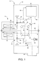
- the transaxle 12 includes a casing 14, a planetary gear type speed reducing device 16 and a bevel gear type differential gear device 18, which are accommodated within the casing 14 so as to be disposed coaxially with the electric drive motor 10.
- the speed reducing device 16 includes a sun gear 22 connected to a motor shaft 20 of the drive motor 10, a plurality of planetary gear pinions 24 meshing with the sun gear 22, a carrier 26 rotatably supporting the planetary gear pinions 24, and a ring gear 28 secured to the casing 14 and meshing with the planetary gear pinions 24.
- the differential gear device 18 includes a shaft 30 which is integrally fixed to the carrier 26 and which is rotated in a plane perpendicular to an axis of the speed reducing device 16, a pair of first bevel gears 32 rotatably mounted on the shaft 30, second bevel gears 34, 36 which are provided so as to be rotatable coaxially with the speed reducing device 16 and which mesh with the respective first bevel gears 32.
- the second bevel gears 34, 36 are splined to respective transmission shafts 38, 40 which are connected to respective left and right drive wheels of the vehicle, such that the second bevel gears 34, 36 are rotated together with the transmission shafts 38, 40.
- the rotation of the motor shaft 20 of the drive motor 10 is inputted to the sun gear 22, and outputted to the differential gear device 18 through the carrier 26, with the ring gear 28 functioning as a reaction element.
- the rotating speed of the carrier 26 is reduced with respect to the sun gear 22 at a predetermined suitable gear ratio of the speed reducing device 16.
- the rotation of the motor 10 is transmitted to the transmission shafts 38, 40 via the speed reducing device 16 and the differential gear device 18.
- the speed reducing device 16, differential gear device 18 and transmission shafts 38, 40 constitute a power transmission system. It is noted that the transaxle 12 as shown in Fig. 1 is made larger than the drive motor 10 as shown in the figure.
- a pump drive gear 44 for driving a mechanical pump in the form of a gear type pump 46.
- the gear pump 46 sucks a lubricating oil from an oil pan 48 formed in the bottom portion of the casing 14, and delivers the lubricating oil, via a forced-feed oil passage 50 formed in the casing 14 and transaxle 12, to selected lubricating points of the power transmission system such as bearing portions of the motor shaft 20 of the drive motor 10, planetary gears 24, transmission shafts 38, 40, meshing portions of the gears of the speed reducing device 16 and the differential gear device 18.
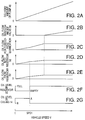
- a delivery amount of the gear pump 46 changes proportionally with a change in the rotation speed of the carrier 26 and the vehicle speed V. As shown in the graph of Fig. 2A, the delivery amount of the gear pump 46 linearly changes with the vehicle speed V.
- the delivery amount of the gear pump 46 is zero when the vehicle speed V is zero, i.e., while the vehicle is stopped.
- the lubricating oil which has been supplied to the lubricating points of the power transmission system drops down from the lubricating points into the bottom portion of the casing 14 or is fed back to the same through a return passage not shown.
- the amount of lubricating oil stored within the casing 14 is predetermined so that the oil bath has an oil level A indicated by an upper broken line in Fig.
- the gear pump 46 may be replaced by any other mechanical pump such as a vane pump or a Roots pump (a lobe-type rotary pump).
- an oil reservoir 52 which is disposed at an upper portion of the casing 14.
- the oil reservoir 52 is adapted to receive a part of the lubricating oil delivered by the gear pump 46.
- the lubricating oil flowing into the oil reservoir 52 is discharged therefrom by gravity at a predetermined flow rate through a drain port 54 formed at the bottom of the oil reservoir 52.
- the amount of the oil discharged from the drain port 54 before the vehicle speed V reaches a predetermined speed SPD1 is equal to an amount of the lubricating oil flowing into the oil reservoir 52.
- the lubricating oil flowing into the oil reservoir 52 is discharged through the drain port 54 without being accumulated in the oil reservoir 52 before the vehicle speed V reaches the speed SPD1.
- the amount of the lubricating oil flowing into the oil reservoir 52 exceeds the amount of discharge from the drain port 54 after the vehicle speed V reaches the speed SPD1 and before the oil reservoir 52 becomes full of the oil.
- the lubricating oil is accumulated in the oil reservoir 52.
- the oil capacity of the oil reservoir 52 is determined such that the lubricating oil stored within the casing 14 has an oil level B indicated by a lower broken line in Fig. 1 when the oil reservoir 52 is full of the lubricating oil.
- This oil level B is determined so that the speed reducing device 16 and the differential gear device 18 are positioned above the oil level B, i.e., these devices are no more immersed in the lubricating oil stored in the bottom portion of the casing 14.
- SPD1 the power transmission system is subject to the oil bath lubrication, with the portions of the speed reducing device 16 and the differential gear device 18 being immersed in the lubricating oil stored in the bottom portion of the casing 14.
- the power transmission system is subject to the forced-feed lubrication wherein the speed reducing device 16 and the differential gear device 18 are lubricated by the lubricating oil delivered by the gear pump 46 and fed through the forced-feed oil passage 50.
- the oil level in the casing 14 is lowered to the level B as described above, at which it is impossible to effect the oil bath lubrication, since the oil level B is below the speed reducing device 16 and the differential gear device 18.
- these devices are subject to only the forced-feed lubrication.
- the predetermined speed SPD1 be set at a value low enough to reduce the energy loss due to agitation of the lubricating oil by the power transmission system while ensuring that the power transmission system is sufficiently forced-feed lubricated only by the lubricating oil delivered by the gear pump 46.
- the value SPD1 is determined to be equal to the vehicle speed at which the rotating speed of the motor shaft 20 of the drive motor 10 is about 1000rpm.
- the value SPD1 depends upon the gear ratio of the speed reducing device 16 and other parameters.
- the size of the drain port 54 is determined so that the lubricating oil starts to be accumulated in the oil reservoir 52 at the thus determined speed SPD1.
- the graphs of Figs. 2A-2G show oil levels and flow rates of the lubricating oil, which vary with the running speed of the vehicle.
- the oil levels and flow rates as shown are those which are established when the vehicle speed is held at each value (e.g., SPD1) for a long time.
- SPD1 e.g. 1
- the oil reservoir 52 is filled with the oil if the vehicle speed is held at the predetermined critical speed SPD1.
- the rate of flow of the lubricating oil into the oil reservoir 52 is constantly equal to the rate of flow of the lubricating oil discharged out of the oil reservoir 52 through the drain port 54 except for the time period as described above.
- the rate of flow of the lubricating oil into the oil reservoir 52 continues to increase with a rise in the hydraulic pressure of the lubricating oil delivered from the gear pump 46, and the rate of discharge flow of the oil from the drain port 54 is accordingly increased.
- the resistance of the lubricating oil to its flow into the oil reservoir 52 is made comparatively large, and the rate of increase of the amount of the lubricating oil used for the forced-feed lubrication of the lubricating points in the power transmission system is accordingly increased.
- a pressure relief valve 56 for preventing an excessive rise of the pressure of the lubricating oil delivered by the gear pump 46, and reducing a load applied to the gear pump 46 so as to minimize the energy loss.
- the relief pressure of the valve 56 is preferably set at a value as low as possible while ensuring that the lubricating points in the power transmission system are adequately lubricated by the lubricating oil delivered from the gear pump 46.
- the relief pressure of the valve 56 may be set, for example, at a level slightly higher than a level which corresponds to the vehicle speed SPD1.
- the power transmission system is principally forced-feed lubricated by the lubricating oil delivered from the gear pump 46.
- the predetermined speed SPD1 the portions of the speed reducing device 16 and the differential gear device 18 are immersed in the lubricating oil bath in the bottom portion of the casing 14. Accordingly, the power transmission system is subject to both the oil bath lubrication and the forced-feed lubrication until the vehicle speed V reaches the predetermined speed SPD1.
- This arrangement assures a satisfactory lubricating effect even when the delivery amount of the gear pump 46 is relatively small, that is, even when the rate of flow of the oil used for the forced-feed lubrication is relatively low, immediately after starting of the vehicle, for instance.
- this arrangement is capable of protecting the bearing portions and the gears of the power transmission system against seizure, wearing and damages which result from shortage of the lubricating oil, thereby assuring considerably improved service life of the components of the power transmission system.
- the gears of the differential gear device 18 are also protected with high reliability from being damaged due to the shortage of the lubricating oil even when the vehicle wheels are slipping on the road surface upon starting of the vehicle.
- the lubricating oil delivered from the gear pump 46 is gradually accumulated in the oil reservoir 52 via the branch oil passage 53.
- the level of the lubricating bath in the bottom portion of the casing 14 falls from the level A to the level B as shown in Fig. 1.
- the speed reducing device 16 and the differential gear device 18 are completely above the level B, making it impossible to lubricate these devices by the oil bath lubrication.
- the power transmission system is mainly forced-feed lubricated by the lubricating oil delivered by the gear pump 46 and fed through the forced-feed oil passage 50, effectively avoiding the energy loss and the overheating of the lubricating oil which would be caused by the agitation of the lubricating oil when the power transmission system is rotated at a relatively high speed.
- the forced-feed lubrication is capable of assuring a satisfactory lubricating effect when the motor shaft 20 of the drive motor 10 is rotated at a relatively high speed.
- the power transmission system is sufficiently lubricated over an entire range of its rotating speed from a relatively low speed to a relatively high speed while reducing the energy loss and avoiding the overheating of the lubricating oil supplied to the lubricating points. Further, the travel distance of the present electric vehicle per one battery charging can be considerably increased as compared with that in the conventional electric vehicle wherein the power transmission system is lubricated only by the oil-bath lubrication. In the present embodiment, the power transmission system which is principally forced-feed lubricated is also oil-bath lubricated when the vehicle running speed is relatively low.
- This arrangement permits reduced cost of manufacture of the lubricating device and reduced electric power consumption of the vehicle, as compared with the electrically-operated forced-feed lubrication system wherein a pump for delivering the lubricating oil is driven by an exclusive electric motor. Further, this arrangement assures a satisfactory lubricating effect with high reliability and permits easy maintenance of the vehicle, eliminating regular checking and replacement of a brush and other components of the electric pump motor.
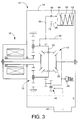
- a lubricating device according to a second embodiment of the present invention, wherein the same reference numerals as used in the preceding first embodiment are used to identify the corresponding components and detailed explanation thereof is dispensed with.
- the branch oil passage 53 is connected to an accumulator 60 in place of the oil reservoir 52 used in the first embodiment.
- the amount of the lubricating oil stored in the casing 14 is predetermined so as to establish an oil level C as indicated by a broken line in Fig. 3, so that the speed reducing device 16 and the differential gear device 18 are positioned above the lubricating oil bath.
- the accumulator 60 has a piston 64 which is biased by a spring 62.
- a predetermined level i.e., a set pressure of the accumulator 60
- the above-indicated set pressure of the accumulator 60 is determined so as to allow the lubricating oil to flow into the accumulator 60 only after a sufficient amount of the lubricating oil is supplied to the lubricating points of the power transmission system.
- the delivered oil is exclusively supplied to the lubricating points for forced-feed lubrication. After a sufficient amount of the oil is delivered to the lubricating points, the oil is allowed to flow into the accumulator 60 and is accumulated therein.
- the set pressure of the accumulator 60 is adjusted as desired by varying the biasing force of the spring 62 or a pre-load acting on the piston 64.
- the accumulator 60 used in this second embodiment may be replaced by any other types of accumulator.
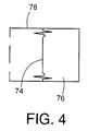
- an accumulator 78 as shown in Fig. 4 may be employed in the present lubricating device. This accumulator 78 has a gas chamber 76 which is partially defined by a diaphragm 74. The set pressure of the accumulator 78 can be adjusted by varying the gas pressure in the chamber 76.
- a check valve 66 between the branch oil passage 53 and the accumulator 60.
- the lubricating oil flows into the accumulator 60 through the check valve 66 when the pressure of the lubricating oil in the branch oil passage 53 is higher than the above-described set pressure of the accumulator 60.
- the present lubricating device is further provided with a discharge line 68 between the accumulator 60 and the branch oil passage 53 such that the discharge line 68 is disposed in parallel with the check valve 66.
- the lubricating oil stored in the accumulator 60 is discharged therefrom into the branch oil passage 53 via the discharge line 68, and then supplied to the lubricating points.
- the discharge line 68 there is provided with an orifice 70 as flow restricting means for restricting a flow rate of the lubricating oil discharged from the accumulator 60.
- the gear pump 46 is turned off upon stopping of the vehicle, the lubricating oil stored in the accumulator 60 is supplied therefrom for a given length of time, i.e., about for 3-5 minutes, which is slightly longer than a usual stop time of the vehicle waiting for a traffic signal light.
- the lubricating points in the power transmission system are lubricated for a while by the lubricating oil discharged from the accumulator 60.
- the amount and set pressure of the accumulator 60 and the cross-sectional area for fluid flow of the orifice 70 are determined such that the lubricating oil is discharged from the accumulator 60 for a desired length of time after the gear pump 46 is turned off.
- the lubricating oil may flow into the accumulator 60 via the discharge line 68 when the pressure of the lubricating oil flowing through the branch oil passage 53 becomes higher than the set pressure of the accumulator 60.
- a sufficient amount of the lubricating oil is delivered by the gear pump 46 to the lubricating points during running of the vehicle, while at the same time, a part of the lubricating oil flows into the accumulator 60 via the branch oil passage 53 and is stored therein.
- the delivery amount of the gear pump 46 decreases with a decrease in the vehicle speed and the oil pressure in the branch oil passage 53 becomes lower than that in the accumulator 60
- the lubricating oil in the accumulator 60 is discharged via the discharge line 68 to the lubricating points at a flow rate controlled by the orifice 70.
- the lubricating device is capable of assuring a satisfactory lubricating effect owing to the lubricating oil discharged from the accumulator 60, when the power transmission system is rotated at a relatively low speed, that is, when the lubricating points of the power transmission system cannot be sufficiently lubricated by the lubricating oil delivered from the gear pump 46.
- the lubricating points in the power transmission system cannot be forced-feed lubricated by the lubricating oil stored in the accumulator 60 as described above.
- this arrangement ensures a satisfactory lubricating effect when the vehicle is restarted after stopping for a relatively short length of time during which the lubricating oil in the accumulator 60 continues to be discharged via the discharge line 68 and delivered to the power transmission system.
- the present lubricating device is capable of protecting the bearing portions and the power transmission gears from suffering from seizure, wearing or damages due to the shortage of the lubricating oil, thereby to assure a considerably improved service life of the components of the power transmission system, as compared with a lubricating device in which the lubricating points are lubricated only by the oil delivered from the gear pump 46.
- the lubricating oil is allowed to flow into the accumulator 60 only after a sufficient amount of the oil is supplied to the lubricating points.
- a comparatively small amount of the lubricating oil can be efficiently utilized for forced-feed lubricating the lubricating points, since the lubricating oil delivered by the gear pump 46 is supplied exclusively to the lubricating points.
- the power transmission system Upon restarting of the vehicle after stopping for a relatively short length of time, the power transmission system is lubricated by the lubricating oil discharged from the accumulator 60.
- the oil stored in the casing 14 upon initial starting of the vehicle is predetermined so as to have a level C as indicated by a broken line in Fig. 3, which is below the speed reducing device 16 and the differential gear device 18.
- the present lubricating device may be modified such that portions of the speed reducing device 16 and the differential gear device 18 are subject to the oil bath lubrication, namely, such that these devices are partially immersed in the lubricating oil bath at the bottom of the casing 14 before the lubricating oil is partly accumulated in the accumulator 60.
- the lubricating oil in the accumulator 60 is forced to be discharged due to the movement of the piston 64 in the biasing direction of the spring 62 when the oil pressure in the branch oil passage 53 becomes lower than that in the accumulator 60.
- the present accumulator 60 has a freedom in setting the rate of discharge flow of the oil from the accumulator 60 since the rate of the discharge flow is adjusted as desired by varying the cross-sectional area of the orifice 70. Further, there is less limitation in determining the location of the accumulator 60, as compared with the lubricating device of the first embodiment wherein the oil reservoir 52 is required to be located above the power transmission system.
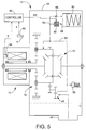
- a lubricating device according to a third embodiment of the present invention.
- a solenoid-operated valve 80 (hereinafter referred to as "solenoid valve") in place of the orifice 70 in the second embodiment of Fig. 3.
- the solenoid valve 80 is selectively placed in an open position and in a closed position under the control of a controller 82.
- the controller 82 is principally constituted by a microcomputer incorporating a CPU (central processing unit), a ROM (read-only memory) and a RAM (random-access memory).
- the controller 82 receives an output signal of a speed sensor 84, which indicates a rotating speed of the motor shaft 20 of the drive motor 10, and an output signal of an accelerator position sensor 86 such as a potentiometer, which indicates an operating amount ⁇ of an accelerator pedal provided on the vehicle.
- the detected rotating speed of the motor shaft 20 is used to obtain a running speed V of the vehicle. Based on the obtained vehicle speed V and the detected operating amount ⁇ , the controller 82 determines whether the lubricating points suffer from the shortage of the lubricating oil.
- the controller 82 If it is determined that the lubricating points suffer from the shortage of the oil, the controller 82 outputs a drive signal SD for placing the solenoid valve 80 in the open position so as to permit the lubricating oil stored in the accumulator 60 to be discharged therefrom into the branch oil passage 53 via the discharge line 68 for lubricating the lubricating points.
- the solenoid valve 80 serves as valve means for permitting or inhibiting the discharge flow of the lubricating oil from the accumulator 60 while the controller 82 serves as valve control means for controlling the solenoid valve 80 to be selectively placed in the open and closed positions.
- the vehicle speed V and the operating amount ⁇ of the accelerator pedal detected by the respective sensors are information necessary for determining whether the lubricating points suffer from the shortage of the oil. It is noted that the operating amount ⁇ of the accelerator pedal corresponds to a load applied to the power transmission system, since the torque of the drive motor 10 is controlled depending on the operating amount ⁇ of the accelerator pedal.
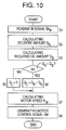
- step S1 determines whether or not the solenoid valve 80 is in the closed position, based on whether the drive signal SD is present or not. If the solenoid valve 80 is in the closed position, an affirmative decision (YES) is obtained and the control flow goes to step S2 to determine whether or not the vehicle speed V is lower than a first threshold VA. If an affirmative decision (YES) is obtained in step S2, step S3 is implemented to determine whether or not the operating amount ⁇ of the accelerator pedal is larger than a first threshold ⁇ A.
- step S3 is followed by step S4 in which the controller outputs the drive signal SD so as to place the solenoid valve 80 in the open position.
- the vehicle speed V is lower than the first threshold VA and the operating amount ⁇ of the accelerator pedal is larger than the first threshold ⁇ A, in other words, when the vehicle is running at a relatively low speed with the accelerator pedal depressed by a considerable amount, the power transmission system is subject to a relatively large load. In this state, for example, immediately after starting of the vehicle, a large amount of the lubricating oil is required for lubricating the lubricating points while the delivery amount of the gear pump 46 is insufficient.
- the controller 82 operates the solenoid valve 80 to be placed in the open position, permitting the lubricating oil stored in the accumulator 60 to be discharged therefrom and supplied to the lubricating points via the discharge line 68 and the branch oil passage 53.
- step S1 if a negative decision (NO) is obtained in step S1, i.e., if the solenoid valve 80 is in the open position, the control flow goes to step S5 to determine whether or not the vehicle speed V is larger than a second threshold VB. If the vehicle speed V is larger than VB, this means that the power transmission system is adequately lubricated by the lubricating oil delivered by the gear pump 46, and therefore, the control flow goes to step S7 wherein the controller 82 terminates the output of the drive signal SD, to close the solenoid valve 82 for inhibiting the discharge flow of the lubricating oil from the accumulator 60.
- NO negative decision
- step S5 is followed by step S6 to determine whether or not the operating amount ⁇ of the accelerator pedal is smaller than a second threshold ⁇ B. If the amount ⁇ is smaller than ⁇ B, it means that the load acting on the power transmission system is not large, and accordingly, the control flow goes to step S7 to place the solenoid valve 80 in the closed position to inhibit the discharge flow of the lubricating oil from the accumulator 60.
- the second threshold VB is set at a value larger than the first threshold VA while the second threshold ⁇ B is set at a value lower than the first threshold ⁇ A.
- the solenoid valve 80 is opened for allowing the lubricating oil to be discharged from the accumulator 60 when the lubricating points suffer from the shortage of the lubricating oil.
- this arrangement permits more effective utilization of the lubricating oil stored in the accumulator 60 for lubricating the power transmission system, as compared with the lubricating device of the preceding embodiment of Fig. 3, whereby the bearing portions and the gears of the power transmission system are protected against seizure, wearing or damages resulting from the shortage of the lubricating oil, so as to assure a further prolonged service life of the components of the power transmission system.
- the solenoid valve 80 is opened when the vehicle speed V is smaller than the predetermined first threshold VA and the operating amount ⁇ of the accelerator pedal is larger than the predetermined first threshold ⁇ A.
- the solenoid valve 80 may be opened according to a suitable data map for opening or closing the valve 80 depending upon the parameters V and ⁇ , so as to permit highly accurate control of the solenoid valve 80.
- the solenoid valve 80 may be controlled by using suitable parameters other than V and ⁇ .
- the planetary gear-type speed reducing device 16 has a carrier 90 in which an accommodating space 92 is formed for accommodating the differential gear device 18.
- the accommodating space 92 receives and stores the lubricating oil delivered by the gear pump 46 and fed through a forced-feed oil passage 94 which is formed through the casing 14 and the transmission shaft 40, whereby the bearing and meshing portions of the gears of the differential gear device 18 in the accommodating space 92 are lubricated by the supplied lubricating oil.
- additional oil passages are formed through the carrier 90 and the transmission shaft 38 so that the bearing and meshing portions of the planetary gears 24 and the bearing portions of the transmission shaft 38 and the motor shaft 20 are lubricated by the supplied lubricating oil.
- To the forced-feed oil passage 94 there is connected an oil reservoir 98 via a branch oil passage 97.
- the oil reservoir 98 receives and stores a part of the lubricating oil delivered by the gear pump 46.
- the lubricating oil stored in the oil reservoir 98 is discharged to the branch oil passage 97 via a discharge line 102 connected to the oil reservoir 98, and is consequently fed into the accommodating space 92 through the forced-feed oil passage 94.
- the discharge line 102 has an orifice 100 as flow restricting means for restricting the rate of discharge flow of the lubricating oil from the oil reservoir 98.
- the differential gear device 18 in the accommodating space 92 is subject to the oil bath lubrication with the portions of the differential gear device 18 being immersed in the lubricating oil in the accommodating space 92.
- the lubricating oil leaks from the accommodating space 92, through the bearing portions of the differential gear device 18, for instance.
- the leaked lubricating oil continues to drop down over a period of from one week to one month, and is consequently collected at the bottom of the casing 14.
- the carrier 90 is provided with a relief valve 96 which is adapted to be placed in an open position against a biasing force of a spring, for instance, due to a centrifugal force when the rotating speed of the power transmission system exceeds a predetermined value.
- a relief valve 96 When the relief valve 96 is placed in the open position, the lubricating oil in the accommodating space 92 is allowed to be discharged outside of the accommodating space 92 through the valve 96.
- the carrier 90 cooperates with the relief valve 96 to constitute an oil retaining member.
- the differential gear device 18 disposed within the accommodating space 92 is subject to the oil bath lubrication, that is, the differential gear device 18 is immersed in the lubricating oil in the accommodating space 92 while the rotating speed of the power transmission system is relatively low and the relief valve 96 is in the closed position for inhibiting the discharge flow of the lubricating oil from the accommodating space 92.
- the rotating speed of the power transmission system is relatively high, that is, when the relief valve 96 is open due to the centrifugal force, the lubricating oil in the accommodating space 92 is discharged outside of the accommodating space 92, making it impossible to oil-bath lubricate the power transmission system.
- the power transmission system is forced-feed lubricated exclusively by the lubricating oil delivered by the gear pump 46.
- This arrangement therefore, assures a satisfactory lubricating effect over an entire range of the rotating speed of the power transmission system from a relatively low speed to a relatively high speed.
- the present lubricating device since the oil bath lubrication can not be effected while the rotating speed of the power transmission system is relatively high as described above, the present lubricating device is free from the energy loss which would result from the agitation of the lubricating oil.
- the lubricating oil is accumulated in the oil reservoir 98 during running of the vehicle, while on the other hand, the lubricating oil is discharged from the oil reservoir 98 by gravity at a controlled flow rate through the orifice 100 when the oil pressure in the branch oil passage 97 is lower than a predetermined level as a result of decrease in the vehicle speed.
- the discharged lubricating oil is fed through the forced-feed oil passage 94, and is consequently accumulated in the accommodating space 92 in which the differential gear device 18 is accommodated, so that the power transmission system is subject to the oil bath lubrication for a suitable period, providing a sufficient lubricating effect when the vehicle is restarted after stopping for a relatively long period.
- the lubricating oil is retained in the accommodating space 92 for a suitable period so that the differential gear device 18 is immersed in the lubricating oil in the accommodating space 92.
- This arrangement assures further effective lubrication especially when the vehicle is restarted after stopping for a relatively long length of time, as compared with the lubricating device according to the second embodiment of Fig. 3 wherein the lubricating oil is adapted to be discharged from the accumulator 60 for a relatively short length of time after the gear pump 46 is turned off.
- the volume of the oil reservoir 98 is sufficient as long as a sufficient amount of the lubricating oil can be supplied to the accommodating space 92, the volume can be made smaller as compared with that of the oil reservoir 52 of the lubricating device according to the first embodiment of Fig. 1, leading to reduction in a total amount of the lubricating oil utilized in the lubricating device.
- a broken line in the accommodating space 92 indicates an oil level which is established when the lubricating oil in the oil reservoir 98 is entirely supplied to the accommodating space 92 after stopping of the vehicle.
- the oil reservoir 98 may be replaced by the accumulator as used in the second or third embodiment.
- the carrier 90 has the relief valve 96 which is adapted to be opened due to the centrifugal force when the rotating speed of the carrier 90 exceeds the predetermined value, whereby the lubricating oil is discharged from the accommodating space 92, terminating the oil bath lubrication within the space 92.
- the present arrangement is free from the conventionally experienced energy loss which would arise if the oil bath lubrication continued while the rotating speed of the power transmission system is relatively high.
- the differential gear device 18 can be adequately lubricated when the vehicle is initially started and when the vehicle is restarted after stopping for a relatively long period, under usual operating condition of the vehicle.
- the carrier 90 and the differential gear device 18 are rotated together.
- the lubricating oil retained in the accommodating space 92 is not agitated by the rotating members of the power transmission system, leading to reduction in the energy loss due to the agitation of the lubricating oil.
- a lubricating device according to a fifth embodiment of the present invention, wherein the lubricating oil is supplied to a power train generally indicated at 110 in Fig. 8 so as to lubricate the power train 110, while at the same time, the oil is supplied to a power steering device indicated at 112 so as to boost a steering force applied to a steering wheel by a vehicle driver.
- the power train 110 includes a power generating device such as the electric drive motor 10 and a power transmission system such as the transaxle 12 as used in the preceding embodiments. Like the power transmission system in the preceding embodiments, the rotating members of the power train 110 are all at rest during stopping of the vehicle.
- a mechanical oil pump 114 such as a gear type pump is connected, directly, or via a gear and a pulley, to a suitable rotating member of the power train 110.
- the oil pump 114 is adapted to deliver the lubricating oil from an oil pan or an oil sump 116 and supply the oil to a supply passage 118 while the vehicle is running in a forward direction.
- a first check valve 120 In the supply passage 118, there is provided a first check valve 120.
- a second check valve 122 is provided in parallel with the oil pump 114.
- check valves 120, 122 are provided so as to prevent the lubricating oil from flowing through the supply passage 118 back toward the pump 114, and further prevent a portion of the supply passage 118 between the first check valve 120 and the oil pump 114 from being evacuated, during a reverse running of the vehicle. It is noted that the lubricating devices in the preceding embodiments may be provided with such check valves for the same purpose as described above. Alternatively, the lubricating devices are constructed such that the oil pump is inhibited from rotating during the reverse running, by providing a one-way clutch, for example.
- an electrically operated pump 124 such that the pump 124 is in parallel connection with the oil pump 114. Accordingly, the lubricating oil delivered by the electric pump 124 as well as the lubricating oil delivered by the mechanical pump 114 flow through the supply passage 118.
- the electric pump 124 is actuated by an electric motor 126 which is rotated by an on-vehicle electric power source such as a battery. The operation of the electric motor 126 is controlled by a controller 128 which serves as means for controlling the electric pump 124.
- the supply passage 118 is connected to a pressure control valve 130, and the hydraulic pressure of the lubricating oil flowing through the supply passage 118 is adjusted to a predetermined level by the pressure control valve 130.
- the lubricating oil whose pressure has been adjusted by the pressure control valve 130 is partially delivered to a rotary valve 132 of the power steering device 112 while on the other hand, the remaining oil is delivered to a flow control valve 136 via an intermediate oil passage 134 and is then supplied to the power train 110 via a supply passage 138 at a controlled flow rate.
- the valve 136 is connected to a drain passage 140 so that the lubricating oil not supplied to the power train 110 is returned to the oil pan 116 through the drain passage 140.
- the pressure control valve 130 and the flow control valve 136 are constructed as shown in Fig. 9.
- the pressure control valve 130 includes a spool 130a, a solenoid coil 130b for biasing the spool 130a in the rightward direction as seen in Fig. 9, and a feedback chamber 130c which receives the lubricating oil supplied from the supply passage 118 via a feedback passage 142.
- the pressure in the feedback chamber 130c acts on the spool 130a in the leftward direction as seen in Fig. 9.
- the pressure control valve 130 adjusts the hydraulic pressure of the lubricating oil in the supply passage 118 such that the biasing force of the solenoid coil 130b is balanced with a pressing force generated by the pressure in the feedback chamber 130c.
- the biasing force of the solenoid coil 130b in other words, the electromagnetic force of the solenoid coil 130b is controlled by the controller 128.
- the rotary valve 132 is adapted to boost the steering force which acts on a steering wheel 144 and which is used for steering the vehicle wheels through a cylinder 146 and a rack not shown.
- the boosting ratio is increased with an increase in the hydraulic pressure applied to the cylinder 146.
- the lubricating oil supplied to the power steering device 112 for boosting the steering force is returned back to the oil pan 116 through a drain passage 148.
- the flow control valve 136 also shown in Fig. 9 includes a spool 136a, a spring 136b for biasing the spool 136a in the leftward direction as seen in Fig. 9, and a feedback chamber 136c which receives the lubricating oil supplied from the intermediate oil passage 134 via a feedback passage 150.
- the pressure in the feedback chamber 136c acts on the spool 136a in the rightward direction as seen in Fig. 9.
- the flow control valve 136 adjusts the pressure of the lubricating oil in the intermediate oil passage 134 such that the biasing force of the spring 136b is balanced with a pressing force generated by the pressure in the feedback chamber 136c.
- the oil pressure in the intermediate oil passage 134 is adjusted to a predetermined constant level which corresponds to the biasing force of the spring 136b.
- the lubricating oil whose pressure is adjusted by the flow control valve 136 is supplied to the power train 110 through a supply passage 138 via a flow restrictor 136d at a predetermined constant flow rate controlled by the restrictor 136d.
- the flow rate is predetermined so that a sufficient lubricating effect is obtained regardless of the rotating speed of the power train 110 and the torque which is transmitted to the power train 110.
- the controller 128 is principally constituted by a microcomputer including a CPU (central processing unit), a RAM (random-access memory) and a ROM (read-only memory).
- the controller 128 receives, from speed detecting means 152 provided with the power train 110, an output signal SNP indicative of a rotating speed NP of a given rotating member in the power train 110.
- the rotating speed NP corresponds to the vehicle speed V.
- the controller 128 applies a solenoid control signal SS to the pressure control valve 130 so as to control a current for energizing the solenoid coil 130b such that the oil pressure adjusted by the pressure valve 130 decreases with an increase in the rotating speed NP, in other words, the force boosted by the power steering device 112 decreases with an increase in the vehicle speed V.
- controller 128 provides a motor control signal SM for controlling the electric motor 126 to be operated at a predetermined speed NM such that the oil pump 124 is actuated by the electric motor 126 to deliver the lubricating oil when the power train 110 is not adequately lubricated by the lubricating oil delivered from the oil pump 114.
- step S1 in which the controller 128 reads in the rotating speed signal SNP generated by the the detecting means 152 of the power train 110.
- step S1 is followed by step S2 to calculate a delivery amount QA of the oil pump 114 based on the rotating speed NP represented by the signal SNP, according to a predetermined equation or data map. Namely, the delivery amount QA can be obtained from the rotating speed NP of the power train 110 since the rotating speed NP coincides with the operating speed of the oil pump 114.
- the control flow then goes to step S3 to calculate an oil amount QB which is required to lubricate the power train 110, on the basis of the rotating speed NP.
- the required amount QB permits the pressure control valve 130 to adjust the pressure of the lubricating oil in the supply passage 118 to the predetermined level according to the solenoid control signal SS supplied from the controller 128.
- the required oil amount QB is a sufficient amount to be supplied to the power train 110 at the controlled flow rate via the pressure control valve 130 and the flow control valve 136.
- the required amount QB can be obtained based on the rotating speed NP according to a suitable equation or data map since the pressure control valve 130 adjusts the pressure of the lubricating oil in the supply passage 118 depending on the rotating speed Np of the power train 110.
- the delivery amount QA increases proportionally with an increase in the rotating speed NP, i.e., the vehicle speed V.
- the required amount QB decreases as a whole with an increase in the vehicle speed V, because the present embodiment is adapted such that the amount supplied to the power train 110 is substantially constant irrespective of a change in the vehicle speed V, and such that the amount supplied to the power steering device 112 decreases with an increase in the vehicle speed V.
- the delivery amount QA is smaller than the required amount QB, and an affirmative decision (YES) is obtained in step S4.
- the delivery amount QA is larger than the required amount QB, and a negative decision (NO) is obtained in step S4.
- step S7 to calculate a motor rotating speed NM at which the electric motor 126 is rotated so as to permit the electric pump 124 to deliver the lubricating oil by an amount equal to the shortage amount QC calculated in step S6.
- the calculation in step S7 to obtain the motor rotating speed NM is effected according to a suitable equation or a data map.
- step S8 wherein the controller 128 generates a motor control signal SM for operating the electric motor 126 at the obtained motor rotating speed NM. It will be understood that a portion of the controller 128 assigned to execute the routine of Fig. 10 serves as pump control means for controlling the motor 126 to control the oil pump 124.
- the lubricating device constructed according to the present embodiment is provided with the electric pump 124 which is actuated by the motor 126 and disposed in parallel with the mechanical oil pump 114.
- the electric pump 124 is controlled by the controller 128 such that the electric pump 124 delivers the lubricating oil by an amount equal to the shortage amount QC when the delivery amount of the mechanical pump 114 is insufficient for lubricating the power train 110.
- a sufficient amount of the lubricating oil can be supplied to the power train 110 by the electric pump 124 during low-speed running of the vehicle or starting of the vehicle, that is, while the delivery amount of the mechanical oil pump 114 is relatively small.
- the power train 110 is protected from seizure, wearing and damages which would be caused by the shortage of the lubricating oil, assuring a considerably improved life expectancy of the bearings and gears, and the power steering device 112 functions in the intended fashion.
- the power train 110 is not always required to be immersed in the lubricating oil since the power train 110 can be adequately lubricated by the oil supplied from the electric pump 124 even upon starting of the vehicle or low-speed running of the vehicle. This provides an advantage of further reducing the energy loss due to the agitation of the oil by the power train during high-speed running of the vehicle.
- the power train 110 can be adequately lubricated by the lubricating oil supplied from the mechanical pump 114, without an operation of the electric pump 124.
- the electric power consumption is reduced in the present lubricating device as compared with the conventional lubricating device wherein the lubricating oil is supplied exclusively by the electric pump.
- the service life of a brush and other components of the electric motor 126 is significantly improved, assuring easy maintenance of the vehicle and improved operating reliability of the lubricating device.
- the motor speed NM at which the electric motor 126 is rotated to actuate the electric pump 124 is accurately controlled in the present embodiment such that the electric pump 124 is capable of supplying the lubricating oil to the power train 110 by an amount equal to the shortage amount QC calculated by the controller 128, leading to further reduction in the electric power consumption and further improvement in the service life of the components of the electric pump 124.
- a solid line shows a relationship between the motor rotating speed NM and the vehicle speed V in the present embodiment while a one-dot chain line shows the relationship in a lubricating device without the mechanical pump 114 wherein the lubricating oil is supplied exclusively by the electric pump 124.
- the operating time of the electric motor 126 is considerably shorter in the present embodiment.
- the present lubricating device is adapted to use a part of the lubricating oil as a working fluid for actuating the power steering device 112. This eliminates an exclusive electric pump for the power steering device 112, thereby to reduce overall cost and weight of the device 112.
- the lubricating oil whose pressure has been adjusted by the pressure control valve 130 and which is not supplied to the power steering device 112 is delivered to the power train 110.
- the lubricating oil delivered from the mechanical oil pump 114 and the electric pump 124 is efficiently utilized for lubricating the power train 110.
- the required oil amount QB for lubricating the power train 110 is reduced, making it possible to reduce a total amount of the electric power to be consumed.
- valve 156 which is employed in place of the pressure control valve 130 and the flow control valve 136 in the lubricating device of Fig. 8.
- This valve 156 includes a spool 156a, a solenoid coil 156b for biasing the spool 156a in the rightward direction as seen in Fig. 12, and a feedback chamber 156c which receives the lubricating oil from the supply passage 118 via the feedback passage 142.
- the pressure in the feedback chamber 156c acts on the spool 156a in the leftward direction as seen in Fig. 12.
- the valve 156 adjusts the oil pressure in the supply passage 118 such that the biasing force of the solenoid coil 156b is balanced with a pressing force generated by the pressure in the feedback chamber 156c.
- the lubricating oil whose pressure has been adjusted by the valve 156 is supplied to the rotary valve 132 of the power steering device 112.
- the lubricating oil which is not supplied to the rotary valve 132 is supplied to the power train 110 by a suitable amount via the supply passage 138, and the remaining oil is fed back to the oil pan 116 via the drain passage 140.
- the second drain passage 148 is connected to the intermediate oil passage 134, and the supply passage 118 is connected to an accumulator 160.
- the lubricating oil discharged from the rotary valve 132 is fed into the intermediate passage 134 through the second drain passage 148.
- the lubricating oil delivered by the oil pump 114 driven by the electric motor 126 is entirely delivered to the flow control valve 136, whereby the lubricating oil is further efficiently utilized for lubricating the power train 110 and the required amount QB of the lubricating oil for lubricating the power train 110 is reduced, leading to reduction in the electric power consumption of the vehicle.
- the present lubricating device is constructed such that the lubricating oil is discharged from the accumulator 160 when the delivery amount of the oil pump 114 is relatively small. This arrangement is effective to reduce the delivery amount of the electric pump 124 so that the electric power consumed by the electric motor 126 is further reduced.
- the volume or pressure of the oil in the accumulator 160 can be detected based on the position of the piston in the accumulator 160 or the hydraulic pressure in the accumulator 160, for instance. Based on the detected volume or pressure in the accumulator 160, the controller 128 determines whether the amount of the lubricating oil is sufficient or not and controls the operation of the electric pump 124.
- the present embodiment may be modified such that the accumulator 160 is replaced by the oil reservoir 52, 98 employed in the preceding embodiments of Figs. 1 and 7. Between the accumulator 160 and the supply passage 118, valve means for permitting or inhibiting the discharge flow of the oil from the accumulator 160 may be provided as in the embodiment of Fig. 5.
- the lubricating devices are used for the transaxle 12 which includes the speed reducing device 16 and the differential gear device 18.
- the construction of the speed reducing device 16 and the differential gear device 18 may be suitably modified.
- the principle of the invention is equally applicable to various types of power transmission system, such as a transmission employing clutches and brakes which are selectively operated to provide a plurality of speed ratios.
- the lubricating oil is supplied to the power train 110 at the substantially constant flow rate, regardless of the changes in the vehicle speed V and the torque which is transmitted to the power train 110 from the electric drive motor 10.
- the flow rate of the lubricating oil supplied to the power train 110 may be controlled by providing a suitable flow control valve such as a solenoid-operated valve capable of automatically adjusting the flow rate, depending upon the load applied to the power train 110, i.e., the rotating speed NP of a rotating member of the power train 110, the torque transmitted to the power train 110, or the rate of change in the transmitted torque.
- the controller 128 calculates the required oil amount QB, taking into account the flow rate adjusted by the flow control valve.
- the pressure of the lubricating oil supplied to the power steering device 112 is adjusted by the pressure control valve 130, based solely on the vehicle speed V, i.e., the rotating speed NP of the power train 110.
- the hydraulic pressure applied to the power steering device 112 may be accurately adjusted by using other parameters such as steering angle, angular velocity, or angular acceleration of the steering wheel 144.
- the power steering device 112 in the fifth and sixth embodiments of Figs. 9 and 13 may be modified to be a speed sensing type wherein the hydraulic pressure in the supply passage 118 is lowered with an increase in the vehicle speed V, if the hydraulic pressure of the lubricating oil delivered from the oil pump 114 is applied to the spool 130a of the pressure control valve 130 in the leftward direction as viewed in Fig. 9. Similar modification of the flow control valve 136 is possible. That is, if the pressure of the oil delivered from the oil pump 114 is applied to the spool 136a in the leftward direction as viewed in Fig. 9, the amount of the lubricating oil supplied to the power train 110 via the supply passage 138 can be increased with an increase in the vehicle speed V.
- the construction of the hydraulic circuits in the fifth and sixth embodiments of Figs. 9 and 13 may also be modified.
- the flow control valve 136 may be eliminated so that the lubricating oil from the pressure control valve 130 is delivered directly to the power train 110 via the intermediate oil passage 134.
- both of the pressure and flow control valves 130, 136 may be eliminated.
- the lubricating oil in the supply passage 118 is directly delivered to the rotary valve 132 of the power steering device 112 while the lubricating oil discharged from the rotary valve 132 is delivered to the power train 110 via the drain passage 148 so as to lubricate the power train 110.
- a lubricating device for a motor vehicle including (a) a power transmission system (16, 18, 38, 40) having rotating members which are all at rest upon stopping of the vehicle, (b) a casing (14) accommodating the power transmission system and storing a lubricating oil, and (c) an oil pump (46) which is driven by the power transmission system and which operates to deliver the oil from the bottom portion of the casing to lubricating points of the power transmission system, wherein an oil reservoir (52) is provided to store a predetermined amount of the oil delivered by the pump, when a delivery amount of the pump exceeds a predetermined value with an increase in the speed of the power transmission system, and the level (A) of the oil stored in the bottom portion of the casing when no oil is stored in the reservoir is determined such that a portion of the power transmission system is immersed in the bath of the lubricating oil, and the oil level (B) when the predetermined amount of the oil delivered by the pump is stored in the reservoir is determined such that the lower end of the power transmission system is located above the oil
Landscapes
- Engineering & Computer Science (AREA)
- General Engineering & Computer Science (AREA)
- Mechanical Engineering (AREA)
- Chemical & Material Sciences (AREA)
- Combustion & Propulsion (AREA)
- Transportation (AREA)
- General Details Of Gearings (AREA)
Priority Applications (1)
| Application Number | Priority Date | Filing Date | Title |
|---|---|---|---|
| EP98118344A EP0895002B1 (de) | 1994-08-12 | 1995-08-10 | Einrichtung zur wirksamen Schmierung eines Kraftübertragungssystems in einem Kraftfahrzeug bei der Inbetriebnahme des Kraftfahrzeugs |
Applications Claiming Priority (6)
| Application Number | Priority Date | Filing Date | Title |
|---|---|---|---|
| JP19025394 | 1994-08-12 | ||
| JP190253/94 | 1994-08-12 | ||
| JP19025394 | 1994-08-12 | ||
| JP119547/95 | 1995-05-18 | ||
| JP11954795 | 1995-05-18 | ||
| JP11954795A JP3322072B2 (ja) | 1994-08-12 | 1995-05-18 | 動力伝達機構の潤滑装置 |
Related Child Applications (1)
| Application Number | Title | Priority Date | Filing Date |
|---|---|---|---|
| EP98118344A Division EP0895002B1 (de) | 1994-08-12 | 1995-08-10 | Einrichtung zur wirksamen Schmierung eines Kraftübertragungssystems in einem Kraftfahrzeug bei der Inbetriebnahme des Kraftfahrzeugs |
Publications (2)
| Publication Number | Publication Date |
|---|---|
| EP0696697A1 true EP0696697A1 (de) | 1996-02-14 |
| EP0696697B1 EP0696697B1 (de) | 1999-11-10 |
Family
ID=26457253
Family Applications (2)
| Application Number | Title | Priority Date | Filing Date |
|---|---|---|---|
| EP95112588A Expired - Lifetime EP0696697B1 (de) | 1994-08-12 | 1995-08-10 | Einrichtung zur wirksamen Schmierung eines Kraftübertragungssystems in einem Kraftfahrzeug bei der Inbetriebnahme des Kraftfahrzeugs |
| EP98118344A Expired - Lifetime EP0895002B1 (de) | 1994-08-12 | 1995-08-10 | Einrichtung zur wirksamen Schmierung eines Kraftübertragungssystems in einem Kraftfahrzeug bei der Inbetriebnahme des Kraftfahrzeugs |
Family Applications After (1)
| Application Number | Title | Priority Date | Filing Date |
|---|---|---|---|
| EP98118344A Expired - Lifetime EP0895002B1 (de) | 1994-08-12 | 1995-08-10 | Einrichtung zur wirksamen Schmierung eines Kraftübertragungssystems in einem Kraftfahrzeug bei der Inbetriebnahme des Kraftfahrzeugs |
Country Status (4)
| Country | Link |
|---|---|
| US (1) | US5662188A (de) |
| EP (2) | EP0696697B1 (de) |
| JP (1) | JP3322072B2 (de) |
| DE (2) | DE69528999T2 (de) |
Cited By (16)
| Publication number | Priority date | Publication date | Assignee | Title |
|---|---|---|---|---|
| EP0731291A3 (de) * | 1995-03-06 | 1997-12-17 | Toyota Jidosha Kabushiki Kaisha | Schmiersystem für Kraftfahrzeuggetriebe |
| GB2322421A (en) * | 1997-02-19 | 1998-08-26 | Delphi France Automotive Sys | Automatic transmission fluid level control |
| EP1918613A2 (de) | 2006-10-26 | 2008-05-07 | Meritor Heavy Vehicle Systems Cameri SpA | Schmiermittelstandregelung bei Antriebskopfanordnungen von Fahrzeugen |
| WO2011051055A1 (de) * | 2009-10-28 | 2011-05-05 | Schaeffler Technologies Gmbh & Co. Kg | Getriebevorrichtung |
| CN103079934A (zh) * | 2010-09-28 | 2013-05-01 | 铃木株式会社 | 电动机驱动车辆的转向系统 |
| CN103547836A (zh) * | 2011-05-20 | 2014-01-29 | Ntn株式会社 | 电动车用减速差动装置 |
| CN105539117A (zh) * | 2014-10-24 | 2016-05-04 | Zf腓德烈斯哈芬股份公司 | 机动车混合动力驱动装置 |
| CN105715785A (zh) * | 2014-12-19 | 2016-06-29 | 保时捷股份公司 | 用于机动车辆的电力驱动装置 |
| CN111692503A (zh) * | 2019-03-15 | 2020-09-22 | 丰田自动车株式会社 | 车辆的润滑结构及车辆的润滑控制方法 |
| DE102020200477A1 (de) | 2020-01-16 | 2021-07-22 | Zf Friedrichshafen Ag | Elektrischer Antrieb für ein Fahrzeug |
| DE102020200476A1 (de) | 2020-01-16 | 2021-07-22 | Zf Friedrichshafen Ag | Elektrischer Antrieb für ein Fahrzeug |
| DE102021109314A1 (de) | 2021-04-14 | 2022-10-20 | Schaeffler Technologies AG & Co. KG | Elektrisch betreibbarer Achsantriebsstrang, Verfahren zur Steuerung eines elektrisch betreibbaren Achsantriebsstrangs, Computerprogrammprodukt und Steuereinrichtung |
| EP4257866A1 (de) | 2022-04-07 | 2023-10-11 | Airbus Helicopters | Mechanisches system mit einem gehäuse, das über schmier- oder kühlelemente eines tanks eines schmierenden fluidsystems untergebracht ist |
| DE102022210589A1 (de) * | 2022-10-06 | 2024-04-11 | Zf Friedrichshafen Ag | Thermisches Management an einem elektrisch antreibbaren Kraftfahrzeug |
| US12110961B2 (en) | 2020-03-18 | 2024-10-08 | Karma Automotive Llc | Transmission system for an electric vehicle |
| EP4493115A1 (de) * | 2022-03-16 | 2025-01-22 | Boston Scientific Scimed, Inc. | Elektronische pumpenanordnung für eine implantierbare vorrichtung mit einem durchflussmodifikator |
Families Citing this family (71)
| Publication number | Priority date | Publication date | Assignee | Title |
|---|---|---|---|---|
| US6092628A (en) * | 1998-09-28 | 2000-07-25 | Caterpillar, Inc. | Apparatus and method for controlling temperature of fluid in a differential assembly |
| US6231323B1 (en) * | 1999-01-15 | 2001-05-15 | Jetstream Of Houston, Inc. | High pressure reciprocating pump |
| JP2001193661A (ja) | 1999-06-08 | 2001-07-17 | Denso Corp | 作動油供給システムおよびその制御方法 |
| US6299561B1 (en) | 1999-07-21 | 2001-10-09 | Meritor Heavy Vehicle Systems, Llc | Device for controlling level of gear lubricant as a function of speed |
| DE19950451A1 (de) * | 1999-10-20 | 2001-04-26 | Zahnradfabrik Friedrichshafen | Vorrichtung zur Schmierung eines Getriebes eines Kraftfahrzeuges |
| JP3867521B2 (ja) * | 2000-09-05 | 2007-01-10 | トヨタ自動車株式会社 | 電動オイルポンプ制御装置 |
| DE112005000055B4 (de) * | 2004-07-16 | 2013-11-07 | Komatsu Ltd. | Schmierölzuführung-Steuervorrichtung für ein Wechselgetriebe |
| US20060054407A1 (en) * | 2004-07-20 | 2006-03-16 | Wirth Kirk L | Transmission lubrication system for towing and method |
| US20060231337A1 (en) * | 2005-04-11 | 2006-10-19 | The Falk Corporation | Elevated oil reservoir collection and distribution system |
| US7866444B2 (en) * | 2006-04-06 | 2011-01-11 | Fairfield Manufacturing Company, Inc. | Cascading oil flow bearing lubrication device |
| JP4959354B2 (ja) * | 2007-01-29 | 2012-06-20 | 本田技研工業株式会社 | 車両駆動装置の油圧回路 |
| US8056662B2 (en) * | 2007-03-23 | 2011-11-15 | Fairfield Manufacturing Company, Inc. | Lubrication system for right-angle drives used with utility vehicles |
| US7954574B2 (en) * | 2007-03-23 | 2011-06-07 | Fairfield Manufacturing Company, Inc. | Offset drive system for utility vehicles |
| JP4893432B2 (ja) * | 2007-04-09 | 2012-03-07 | トヨタ自動車株式会社 | 自動変速機のオイルレベル調整装置 |
| DE102007041584A1 (de) * | 2007-09-01 | 2009-03-05 | Zf Friedrichshafen Ag | Anordnung einer elektrisch betriebenen Ölpumpe eines Automatgetriebes |
| JP4966874B2 (ja) * | 2008-01-08 | 2012-07-04 | 株式会社ユニバンス | 動力伝達装置 |
| JP4757885B2 (ja) * | 2008-01-31 | 2011-08-24 | 本田技研工業株式会社 | 車両駆動装置 |
| JP2009192045A (ja) * | 2008-02-18 | 2009-08-27 | Ntn Corp | 鉄道車両駆動ユニット |
| JP2009222159A (ja) * | 2008-03-17 | 2009-10-01 | Toyota Motor Corp | 潤滑液供給機構 |
| JP5157604B2 (ja) * | 2008-04-08 | 2013-03-06 | トヨタ自動車株式会社 | インホイールモータ |
| US8133143B2 (en) * | 2008-06-16 | 2012-03-13 | Fairfield Manufacturing Company, Inc. | Gear reducer electric motor assembly with internal brake |
| US8152674B2 (en) * | 2008-08-15 | 2012-04-10 | Arvinmeritor Technology, Llc | Auxiliary lubrication pump for carriers |
| US8056666B2 (en) * | 2008-10-10 | 2011-11-15 | GM Global Technology Operations LLC | Hydraulic control for a vehicle powertrain |
| US8997449B2 (en) * | 2008-12-22 | 2015-04-07 | Pratt & Whitney Canada Corp. | Flow restrictor for lubrication line |
| US8049384B2 (en) * | 2009-06-19 | 2011-11-01 | GM Global Technology Operations LLC | Electronic drive unit |
| GB2471652A (en) * | 2009-06-30 | 2011-01-12 | Meritor Technology Inc | Transmission system with a reservoir and a sump for crown wheel lubricating oil |
| GB2471653A (en) * | 2009-06-30 | 2011-01-12 | Meritor Technology Inc | A method of controlling a fluid level around a transmission gear |
| US8323143B2 (en) * | 2009-12-02 | 2012-12-04 | Fairfield Manufacturing Company, Inc. | Integrated spindle-carrier electric wheel drive |
| JP5201191B2 (ja) * | 2010-10-08 | 2013-06-05 | 三菱自動車工業株式会社 | ハイブリット車のクラッチ制御装置 |
| KR20140002730A (ko) * | 2011-02-09 | 2014-01-08 | 알리손 트랜스미션, 인크. | 스캐빈지 펌프 오일 레벨 제어 시스템 및 방법 |
| JP2012189202A (ja) * | 2011-02-24 | 2012-10-04 | Ntn Corp | 遊星歯車装置 |
| JP2013040665A (ja) * | 2011-08-18 | 2013-02-28 | Ntn Corp | 遊星歯車装置 |
| ES2496417T3 (es) | 2011-11-30 | 2014-09-19 | Siemens Aktiengesellschaft | Engranaje para aplicaciones industriales o instalaciones de energía eólica |
| US20130232962A1 (en) * | 2012-03-06 | 2013-09-12 | GM Global Technology Operations LLC | Hydraulic control for a vehicle powertrain |
| US8855878B2 (en) * | 2012-08-09 | 2014-10-07 | Gm Global Technology Operations, Llc. | System and method for controlling an accumulator based on vehicle conditions |
| DE102012221400A1 (de) * | 2012-11-22 | 2014-06-05 | Aktiebolaget Skf | Lagerträgereinheit und Herstellungsverfahren zur Herstellung einer Lagerträgereinheit |
| DE102012221399A1 (de) * | 2012-11-22 | 2014-05-22 | Aktiebolaget Skf | Lagerträgereinheit und Sensierverfahren |
| US9068645B2 (en) | 2012-12-14 | 2015-06-30 | GM Global Technology Operations LLC | Transmission sump level control system |
| JP2014137099A (ja) * | 2013-01-16 | 2014-07-28 | Jatco Ltd | 変速機の制御装置 |
| GB2511085A (en) * | 2013-02-22 | 2014-08-27 | Harper Adams University | Electric drive system |
| US9366334B2 (en) | 2014-05-06 | 2016-06-14 | Borgwarner Inc. | Lubrication system and transfer case incorporating the same |
| GB201409180D0 (en) * | 2014-05-23 | 2014-07-09 | Qinetiq Ltd | Improvements to oil pumps for motor vehicles |
| DE102014016173A1 (de) * | 2014-11-03 | 2016-05-04 | Audi Ag | Antriebseinrichtung für ein Kraftfahrzeug |
| JP6191585B2 (ja) | 2014-11-19 | 2017-09-06 | トヨタ自動車株式会社 | ハイブリッド車両の制御装置 |
| JP6386375B2 (ja) * | 2014-12-29 | 2018-09-05 | 株式会社日立製作所 | 風力発電設備および増速機 |
| JP6194911B2 (ja) | 2015-03-13 | 2017-09-13 | トヨタ自動車株式会社 | ハイブリッド車両の潤滑構造 |
| JP6458623B2 (ja) * | 2015-04-24 | 2019-01-30 | 日産自動車株式会社 | 駆動ユニット |
| US10124844B2 (en) * | 2015-04-28 | 2018-11-13 | Cnh Industrial America Llc | System and method for supplying fluid to a track drive box of a work vehicle |
| US10738668B2 (en) | 2015-07-10 | 2020-08-11 | Gkn Driveline North America, Inc. | Automotive driveline unit housing with lubricant feed passage and flow restrictor |
| WO2017027180A1 (en) | 2015-08-07 | 2017-02-16 | Sikorsky Aircraft Corporation | Lubrication systems for transmissions |
| US10309524B2 (en) | 2016-02-03 | 2019-06-04 | Toyota Jidosha Kabushiki Kaisha | Lubricating device of power transmission device for vehicle |
| US9964199B2 (en) | 2016-04-12 | 2018-05-08 | GM Global Technology Operations LLC | Transmission storage oil level control with a solenoid on and off pulse |
| DE112017003474B4 (de) | 2016-09-30 | 2024-05-23 | Aisin Corporation | Fahrzeugantriebsgerät |
| JP6809393B2 (ja) * | 2017-06-20 | 2021-01-06 | トヨタ自動車株式会社 | 車両用動力伝達装置の潤滑装置 |
| JP6929143B2 (ja) | 2017-06-27 | 2021-09-01 | 川崎重工業株式会社 | ヘリコプタ用の潤滑装置 |
| JP6951992B2 (ja) * | 2018-03-16 | 2021-10-20 | 本田技研工業株式会社 | 車両用動力伝達装置 |
| JP6996474B2 (ja) * | 2018-10-31 | 2022-01-17 | トヨタ自動車株式会社 | 動力伝達装置の潤滑装置 |
| JP7111006B2 (ja) * | 2019-01-25 | 2022-08-02 | トヨタ自動車株式会社 | 車両用動力伝達装置 |
| DE102019105174A1 (de) * | 2019-02-28 | 2020-09-03 | Kessler & Co Gmbh & Co.Kg | Achsmittengetriebe |
| US11047470B2 (en) * | 2019-03-26 | 2021-06-29 | Dana Heavy Vehicle Systems Group, Llc | Axle assembly with lubrication pump |
| KR20210003457A (ko) * | 2019-07-02 | 2021-01-12 | 현대자동차주식회사 | 차량용 열 관리 시스템 |
| US11355996B2 (en) * | 2019-11-06 | 2022-06-07 | Neapco Intellectual Property Holdings, Llc | Lubricant supported electric motor with controlled and balanced lubricant flow |
| US11898630B2 (en) | 2019-11-14 | 2024-02-13 | Aisin Corporation | Vehicle drive apparatus |
| US20210190203A1 (en) * | 2019-12-20 | 2021-06-24 | GM Global Technology Operations LLC | Transmission hydraulic control system |
| FR3114861B1 (fr) * | 2020-10-01 | 2022-08-19 | Airbus Helicopters | Système de lubrification avec un réservoir de secours |
| JP7580900B2 (ja) * | 2022-03-23 | 2024-11-12 | ジヤトコ株式会社 | 動力伝達装置 |
| WO2023224957A2 (en) | 2022-05-17 | 2023-11-23 | Borgwarner Inc. | Electric vehicle transmission |
| EP4526579A1 (de) * | 2022-05-17 | 2025-03-26 | BorgWarner Inc. | Elektrofahrzeuggetriebe |
| US20250277523A1 (en) * | 2022-05-17 | 2025-09-04 | Borgwarner Inc. | Electric vehicle transmission |
| DE102022205855A1 (de) | 2022-06-08 | 2023-12-14 | Zf Friedrichshafen Ag | Antriebsanordnung für ein Fahrzeug, elektrische Achse mit der Antriebsanordnung sowie Verfahren zum Betreiben der Antriebsanordnung |
| KR20260004042A (ko) * | 2024-07-01 | 2026-01-08 | 현대자동차주식회사 | 구동장치 윤활 구조 |
Citations (10)
| Publication number | Priority date | Publication date | Assignee | Title |
|---|---|---|---|---|
| US2861477A (en) * | 1955-11-21 | 1958-11-25 | Mueller Otto | Pump and lock for differential |
| EP0074799A2 (de) * | 1981-09-10 | 1983-03-23 | General Electric Company | Schmiervorrichtung unabhängig von der Lage |
| DE3208100A1 (de) * | 1982-03-06 | 1983-09-15 | Zahnradfabrik Friedrichshafen Ag, 7990 Friedrichshafen | Getriebegehaeuse mit tauchschmierung |
| US4751858A (en) * | 1985-12-12 | 1988-06-21 | Toyota Jidosha Kabushiki Kaisha | Device for controlling quantity of lubricating oil in automatic transmission for vehicle |
| DE3921932A1 (de) * | 1989-07-04 | 1991-01-17 | Daimler Benz Ag | Gangwechselgetriebe mit kammern zum sammeln und zwischenspeichern von schmiermittel |
| EP0443901A1 (de) * | 1990-02-20 | 1991-08-28 | AEROSPATIALE Société Nationale Industrielle | Hauptgetriebe eines Drehflügelflugzeugs mit einer Notschmiereinrichtung |
| DE4035624A1 (de) * | 1990-11-09 | 1992-05-14 | Audi Ag | Differential fuer kraftfahrzeuge |
| US5115887A (en) * | 1991-04-22 | 1992-05-26 | General Motors Corporation | Common hydraulic circuitry for a scavenge and towing system |
| JPH0589061U (ja) | 1991-04-16 | 1993-12-03 | 株式会社フジユニバンス | トランスファ装置の潤滑構造 |
| GB2273323A (en) * | 1992-12-10 | 1994-06-15 | Honda Motor Co Ltd | Oil pump driving device for transmission has drive from electric motor at low engine speeds |
Family Cites Families (11)
| Publication number | Priority date | Publication date | Assignee | Title |
|---|---|---|---|---|
| US1176936A (en) * | 1913-03-14 | 1916-03-28 | Packard Motor Car Co | Motor-vehicle. |
| DE2715771A1 (de) * | 1977-04-07 | 1978-10-12 | Hurth Masch Zahnrad Carl | Schmiereinrichtung fuer getriebe o.dgl. im anfahrzustand |
| DE3209514C2 (de) * | 1982-03-16 | 1984-04-26 | BHS-Bayerische Berg-, Hütten- und Salzwerke AG, 8000 München | In sich geschlossene Getriebeanlage mit Druckschmierung |
| DE3566722D1 (en) * | 1984-07-06 | 1989-01-12 | Neuenstein Zahnradwerk | Immersion lubrication system for gear-boxes of motor vehicles |
| JPS61153063A (ja) * | 1984-12-26 | 1986-07-11 | Aisin Warner Ltd | 動力伝達用チエ−ンの潤滑装置 |
| JPS61167772A (ja) * | 1985-01-19 | 1986-07-29 | Aisin Warner Ltd | 伝動機構の潤滑油供給装置 |
| JPH0658052B2 (ja) * | 1985-07-18 | 1994-08-03 | ヤマハ発動機株式会社 | 2サイクルエンジンの潤滑方法 |
| JPH038816A (ja) * | 1989-06-05 | 1991-01-16 | Nippon Mengiyou Gijutsu Keizai Kenkyusho | 繊維ウエブの製造方法および繊維ウエブ製造装置 |
| US4962830A (en) * | 1989-09-18 | 1990-10-16 | Frank Potts | Dual transmission-fluid-level maintenance system |
| JPH0442955U (de) * | 1990-08-08 | 1992-04-13 | ||
| JP3182806B2 (ja) * | 1991-09-20 | 2001-07-03 | 株式会社日立製作所 | バージョンアップ方法 |
-
1995
- 1995-05-18 JP JP11954795A patent/JP3322072B2/ja not_active Expired - Fee Related
- 1995-07-14 US US08/502,619 patent/US5662188A/en not_active Expired - Fee Related
- 1995-08-10 EP EP95112588A patent/EP0696697B1/de not_active Expired - Lifetime
- 1995-08-10 DE DE69528999T patent/DE69528999T2/de not_active Expired - Fee Related
- 1995-08-10 EP EP98118344A patent/EP0895002B1/de not_active Expired - Lifetime
- 1995-08-10 DE DE69513240T patent/DE69513240T2/de not_active Expired - Fee Related
Patent Citations (10)
| Publication number | Priority date | Publication date | Assignee | Title |
|---|---|---|---|---|
| US2861477A (en) * | 1955-11-21 | 1958-11-25 | Mueller Otto | Pump and lock for differential |
| EP0074799A2 (de) * | 1981-09-10 | 1983-03-23 | General Electric Company | Schmiervorrichtung unabhängig von der Lage |
| DE3208100A1 (de) * | 1982-03-06 | 1983-09-15 | Zahnradfabrik Friedrichshafen Ag, 7990 Friedrichshafen | Getriebegehaeuse mit tauchschmierung |
| US4751858A (en) * | 1985-12-12 | 1988-06-21 | Toyota Jidosha Kabushiki Kaisha | Device for controlling quantity of lubricating oil in automatic transmission for vehicle |
| DE3921932A1 (de) * | 1989-07-04 | 1991-01-17 | Daimler Benz Ag | Gangwechselgetriebe mit kammern zum sammeln und zwischenspeichern von schmiermittel |
| EP0443901A1 (de) * | 1990-02-20 | 1991-08-28 | AEROSPATIALE Société Nationale Industrielle | Hauptgetriebe eines Drehflügelflugzeugs mit einer Notschmiereinrichtung |
| DE4035624A1 (de) * | 1990-11-09 | 1992-05-14 | Audi Ag | Differential fuer kraftfahrzeuge |
| JPH0589061U (ja) | 1991-04-16 | 1993-12-03 | 株式会社フジユニバンス | トランスファ装置の潤滑構造 |
| US5115887A (en) * | 1991-04-22 | 1992-05-26 | General Motors Corporation | Common hydraulic circuitry for a scavenge and towing system |
| GB2273323A (en) * | 1992-12-10 | 1994-06-15 | Honda Motor Co Ltd | Oil pump driving device for transmission has drive from electric motor at low engine speeds |
Cited By (26)
| Publication number | Priority date | Publication date | Assignee | Title |
|---|---|---|---|---|
| EP0731291A3 (de) * | 1995-03-06 | 1997-12-17 | Toyota Jidosha Kabushiki Kaisha | Schmiersystem für Kraftfahrzeuggetriebe |
| GB2322421A (en) * | 1997-02-19 | 1998-08-26 | Delphi France Automotive Sys | Automatic transmission fluid level control |
| GB2322421B (en) * | 1997-02-19 | 2001-02-07 | Delphi France Automotive Sys | Automatic transmission |
| EP1918613A2 (de) | 2006-10-26 | 2008-05-07 | Meritor Heavy Vehicle Systems Cameri SpA | Schmiermittelstandregelung bei Antriebskopfanordnungen von Fahrzeugen |
| EP1918613A3 (de) * | 2006-10-26 | 2008-06-18 | Meritor Heavy Vehicle Systems Cameri SpA | Schmiermittelstandregelung bei Antriebskopfanordnungen von Fahrzeugen |
| WO2011051055A1 (de) * | 2009-10-28 | 2011-05-05 | Schaeffler Technologies Gmbh & Co. Kg | Getriebevorrichtung |
| CN103079934B (zh) * | 2010-09-28 | 2016-02-10 | 铃木株式会社 | 电动机驱动车辆的转向系统 |
| CN103079934A (zh) * | 2010-09-28 | 2013-05-01 | 铃木株式会社 | 电动机驱动车辆的转向系统 |
| CN103547836B (zh) * | 2011-05-20 | 2017-03-01 | Ntn株式会社 | 电动车用减速差动装置 |
| EP2711589A4 (de) * | 2011-05-20 | 2015-05-27 | Ntn Toyo Bearing Co Ltd | Reduktionsdifferentialgetriebevorrichtung für elektrofahrzeuge |
| CN103547836A (zh) * | 2011-05-20 | 2014-01-29 | Ntn株式会社 | 电动车用减速差动装置 |
| CN105539117A (zh) * | 2014-10-24 | 2016-05-04 | Zf腓德烈斯哈芬股份公司 | 机动车混合动力驱动装置 |
| CN105539117B (zh) * | 2014-10-24 | 2019-12-10 | Zf腓德烈斯哈芬股份公司 | 机动车混合动力驱动装置 |
| CN105715785A (zh) * | 2014-12-19 | 2016-06-29 | 保时捷股份公司 | 用于机动车辆的电力驱动装置 |
| CN105715785B (zh) * | 2014-12-19 | 2017-11-03 | 保时捷股份公司 | 用于机动车辆的电力驱动装置 |
| CN111692503A (zh) * | 2019-03-15 | 2020-09-22 | 丰田自动车株式会社 | 车辆的润滑结构及车辆的润滑控制方法 |
| DE102020200476A1 (de) | 2020-01-16 | 2021-07-22 | Zf Friedrichshafen Ag | Elektrischer Antrieb für ein Fahrzeug |
| DE102020200477A1 (de) | 2020-01-16 | 2021-07-22 | Zf Friedrichshafen Ag | Elektrischer Antrieb für ein Fahrzeug |
| US12110961B2 (en) | 2020-03-18 | 2024-10-08 | Karma Automotive Llc | Transmission system for an electric vehicle |
| DE102021109314A1 (de) | 2021-04-14 | 2022-10-20 | Schaeffler Technologies AG & Co. KG | Elektrisch betreibbarer Achsantriebsstrang, Verfahren zur Steuerung eines elektrisch betreibbaren Achsantriebsstrangs, Computerprogrammprodukt und Steuereinrichtung |
| DE102021109314B4 (de) | 2021-04-14 | 2023-02-23 | Schaeffler Technologies AG & Co. KG | Elektrisch betreibbarer Achsantriebsstrang |
| EP4493115A1 (de) * | 2022-03-16 | 2025-01-22 | Boston Scientific Scimed, Inc. | Elektronische pumpenanordnung für eine implantierbare vorrichtung mit einem durchflussmodifikator |
| EP4257866A1 (de) | 2022-04-07 | 2023-10-11 | Airbus Helicopters | Mechanisches system mit einem gehäuse, das über schmier- oder kühlelemente eines tanks eines schmierenden fluidsystems untergebracht ist |
| FR3134440A1 (fr) * | 2022-04-07 | 2023-10-13 | Airbus Helicopters | Système mécanique muni d’un carter logeant au-dessus d’éléments à lubrifier ou à refroidir un réservoir d’un système fluidique lubrifiant |
| US11835126B2 (en) | 2022-04-07 | 2023-12-05 | Airbus Helicopters | Mechanical system provided with a sump receiving, above components to be lubricated or cooled, a tank of a lubricating fluid system |
| DE102022210589A1 (de) * | 2022-10-06 | 2024-04-11 | Zf Friedrichshafen Ag | Thermisches Management an einem elektrisch antreibbaren Kraftfahrzeug |
Also Published As
| Publication number | Publication date |
|---|---|
| EP0895002A2 (de) | 1999-02-03 |
| US5662188A (en) | 1997-09-02 |
| JP3322072B2 (ja) | 2002-09-09 |
| DE69528999D1 (de) | 2003-01-09 |
| JPH08105520A (ja) | 1996-04-23 |
| DE69513240D1 (de) | 1999-12-16 |
| EP0696697B1 (de) | 1999-11-10 |
| DE69513240T2 (de) | 2000-06-08 |
| DE69528999T2 (de) | 2003-04-24 |
| EP0895002B1 (de) | 2002-11-27 |
| EP0895002A3 (de) | 1999-10-20 |
Similar Documents
| Publication | Publication Date | Title |
|---|---|---|
| US5662188A (en) | Device for effective lubrication of vehicle power transmission system upon starting of vehicle | |
| US9377099B2 (en) | Transmission system | |
| US6299561B1 (en) | Device for controlling level of gear lubricant as a function of speed | |
| US7240486B2 (en) | Electro-hydraulic system for fan driving and brake charging | |
| US8108115B2 (en) | Vehicle control device | |
| CN105299200B (zh) | 用于机动车辆的变速箱 | |
| US8042331B2 (en) | On-demand hydraulic pump for a transmission and method of operation | |
| US8845488B2 (en) | Hydraulic control apparatus and hydraulic control method | |
| EP1231414B1 (de) | Hydrauliksteuerungsvorrichtung und -verfahren eines Fahrzeugs | |
| GB2471653A (en) | A method of controlling a fluid level around a transmission gear | |
| US9145931B2 (en) | Control device for vehicular lockup clutch | |
| US7958983B2 (en) | Hydraulic system in motor vehicles | |
| JP2017155888A (ja) | 車両の駆動系の潤滑装置 | |
| CN107110350A (zh) | 自动变速器 | |
| JP5673446B2 (ja) | 車両制御装置 | |
| JP5369631B2 (ja) | 変速機における油面レベルの制御方法及びその装置 | |
| CN111207203A (zh) | 动力传递装置的润滑系统 | |
| JP4881501B2 (ja) | 車両用自動変速機における潤滑油量制御装置 | |
| JPH0437307B2 (de) | ||
| KR19980077698A (ko) | 오토매틱 트랜스미션용 오일의 적정 유량 조절장치 | |
| JP2010210058A (ja) | 車両の制御装置 | |
| JPH0212304B2 (de) |
Legal Events
| Date | Code | Title | Description |
|---|---|---|---|
| PUAI | Public reference made under article 153(3) epc to a published international application that has entered the european phase |
Free format text: ORIGINAL CODE: 0009012 |
|
| 17P | Request for examination filed |
Effective date: 19950810 |
|
| AK | Designated contracting states |
Kind code of ref document: A1 Designated state(s): DE FR GB |
|
| 17Q | First examination report despatched |
Effective date: 19970429 |
|
| GRAG | Despatch of communication of intention to grant |
Free format text: ORIGINAL CODE: EPIDOS AGRA |
|
| GRAG | Despatch of communication of intention to grant |
Free format text: ORIGINAL CODE: EPIDOS AGRA |
|
| GRAH | Despatch of communication of intention to grant a patent |
Free format text: ORIGINAL CODE: EPIDOS IGRA |
|
| GRAH | Despatch of communication of intention to grant a patent |
Free format text: ORIGINAL CODE: EPIDOS IGRA |
|
| GRAA | (expected) grant |
Free format text: ORIGINAL CODE: 0009210 |
|
| AK | Designated contracting states |
Kind code of ref document: B1 Designated state(s): DE FR GB |
|
| REF | Corresponds to: |
Ref document number: 69513240 Country of ref document: DE Date of ref document: 19991216 |
|
| ET | Fr: translation filed | ||
| PLBE | No opposition filed within time limit |
Free format text: ORIGINAL CODE: 0009261 |
|
| STAA | Information on the status of an ep patent application or granted ep patent |
Free format text: STATUS: NO OPPOSITION FILED WITHIN TIME LIMIT |
|
| 26N | No opposition filed | ||
| REG | Reference to a national code |
Ref country code: GB Ref legal event code: IF02 |
|
| PGFP | Annual fee paid to national office [announced via postgrant information from national office to epo] |
Ref country code: GB Payment date: 20030806 Year of fee payment: 9 |
|
| PGFP | Annual fee paid to national office [announced via postgrant information from national office to epo] |
Ref country code: FR Payment date: 20030808 Year of fee payment: 9 |
|
| PGFP | Annual fee paid to national office [announced via postgrant information from national office to epo] |
Ref country code: DE Payment date: 20030822 Year of fee payment: 9 |
|
| REG | Reference to a national code |
Ref country code: GB Ref legal event code: 746 Effective date: 20040505 |
|
| REG | Reference to a national code |
Ref country code: FR Ref legal event code: D6 |
|
| PG25 | Lapsed in a contracting state [announced via postgrant information from national office to epo] |
Ref country code: GB Free format text: LAPSE BECAUSE OF NON-PAYMENT OF DUE FEES Effective date: 20040810 |
|
| PG25 | Lapsed in a contracting state [announced via postgrant information from national office to epo] |
Ref country code: DE Free format text: LAPSE BECAUSE OF NON-PAYMENT OF DUE FEES Effective date: 20050301 |
|
| GBPC | Gb: european patent ceased through non-payment of renewal fee |
Effective date: 20040810 |
|
| PG25 | Lapsed in a contracting state [announced via postgrant information from national office to epo] |
Ref country code: FR Free format text: LAPSE BECAUSE OF NON-PAYMENT OF DUE FEES Effective date: 20050429 |
|
| REG | Reference to a national code |
Ref country code: FR Ref legal event code: ST |